Rangemaster classic deluxe 100 User's Manual & Installation Instructions
Hide thumbs
Also See for classic deluxe 100:
- User's manual & installation instructions (44 pages) ,
- User's manual & installation instructions (36 pages) ,
- User's manual & installation instructions (48 pages)

Related Manuals for Rangemaster classic deluxe 100


Summary of Contents for Rangemaster classic deluxe 100
-
Page 1: Installation Instructions
Built from experience USER GUIDE & INSTALLATION INSTRUCTIONS Classic Deluxe and Professional + 100 Induction U110683-02... - Page 2 Terms & Conditions 1. This is my Rangemaster is open to residents of UK mainland only, aged 18 years & over. 2. All entries should be submitted to the advertised e-mail address, or Rangemaster UK Facebook, Instagram or Twitter page using the advertised hashtag &...
-
Page 3: Table Of Contents
Contents Before You Start... Cleaning Your Cooker Personal Safety Electrical Connection Safety Glide-out Grill™ Ventilation Control Panel and Doors Induction and Ceramic Care Ovens Oven Care The Tall Oven Cooker Care Cleaning Table Hob Care Troubleshooting Grill/Glide-out Grill™ Care Installation Cooling Fan Cleaning Dear Installer... -
Page 5: Before You Start
1. Before You Start... Personal Safety This User Guide covers a number of different models. Although some of the illustrations will look different to This appliance is for cooking purposes only. It must not be your particular model the functions will be the same. We used for other purposes, for example heating a room. -
Page 6: Electrical Connection Safety
Electrical Connection Safety Maintenance The electrical installation must be installed in accordance • It is recommended that this appliance is serviced with all relevant British Standards/Codes of Practice, annually. BS 7671. Or with the relevant national and local • DO NOT use cooking vessels on the hotplate that regulations and with the local gas and electricity supply overlap the edges. -
Page 7: Induction And Ceramic Care
• Flammable materials may explode and result in fire or Fig. 1.1 property damage. ArtNo.312-0001 Not cooking surface Induction and Ceramic Care • Important information for pacemaker and implanted insulin pump users: The functions of this hob comply with the applicable European standards on electromagnetic interference. -
Page 8: Oven Care
• We recommend that you avoid wiping any surface unit Fig. 1.4 areas until they have cooled and the indicator light has gone off. Sugar spills are the exception to this (see ‘Cleaning your Cooker’). After cleaning, use a dry cloth or paper towel to remove any cleaning cream residue. -
Page 9: Hob Care
Hob Care Cleaning • NEVER allow anyone to climb or stand on the hob. • Isolate the electricity supply before carrying out any thorough cleaning. Allow the cooker to cool. • DO NOT use the hob surface as a cutting board. •... -
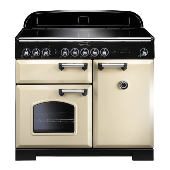
Page 10: Cooker Overview
2. Cooker Overview Fig. 2.1 The 100 induction cooker (Fig. 2.1) has the following Fig. 2.2 features: 5 induction cooking zones A control panel A separate glide-out grill A fan oven or multifunction oven (depending on model) Tall fan oven The Hob Use only pans that are suitable for induction hobs. - Page 11 The very best pans have bases that are very slightly curved Fig. 2.3 up when cold (Fig. 2.3). If you hold a ruler across the bottom you will see a small gap in the middle. When they heat up the metal expands and lies flat on the cooking surface.
- Page 12 Residual Heat Indicator, H Automatic heat-up time at Power Level 100% (min:sec) After use, a cooking zone will remain hot for a while as heat 0:48 dissipates. When a cooking zone is switched off the residual heat indicator symbol [H ], will appear in the display. This 2:24 shows that the cooking zone temperature is above 60 °C and 3:50...
- Page 13 Low Temperature Setting, L1/L2 Maximum Operating Time Power Level This function should only be used when cooking from cold. 2 hours L1 and L2 Each cooking area is equipped with 2 low temperature 6 hours settings: 6 hours 5 hours •...
-
Page 14: The Glide-Out Grill
Overheat Function Fig. 2.9 This function identifies when the temperature of the pan rises rapidly and works to maintain a safe level of pan temperature. It should not interfere with normal cooking. Cookware with bases that become distorted (Fig. 2.2) when heated may interfere with the operation of the Overheat Function. -
Page 15: The Ovens
The Ovens Fig. 2.14 The clock must be set to the time of day before the ovens will work. See the following section on ‘The Clock’ for instructions on setting the time of day. Multi-function oven References to ‘left-hand’ and ‘right-hand’ ovens apply as viewed from the front of the appliance. - Page 16 Multi-function Oven Functions Fan Assisted Oven This function operates the fan, circulating air heated Rapid Response by the elements at the top and the base of the oven. The Rapid Response setting enables you to preheat The combination of fan and conventional cooking the oven faster than normal.
-
Page 17: Main Oven Light
Defrost Fig. 2.17 This function operates the fan to circulate cold air only. Make sure the temperature control is at 0°C and that no heat is applied. This enables small items such ArtNo.235-0003 - Classic DL MF knobs as desserts, cream cakes and pieces of meat, fish and poultry to be defrosted. -
Page 18: Accessories
Accessories Fig. 2.21 Shelf guard Oven Shelves – Left-hand (Main) Oven The oven shelves (Fig. 2.21) are retained when pulled forward but can be easily removed and refitted. Pull the shelf forward until the back of the shelf is stopped by the shelf stop bumps in the oven sides (Fig. -
Page 19: The Clock
3. The Clock The clock must be set to the time of day before the oven Fig. 3.1 ArtNo.300-0005 2BC will work. minute minder setting The 2-button Clock Setting the Clock Once the cooker is connected and switched on, the display will start to flash. - Page 20 To Stop the Oven at a Specific Time of Fig. 3.5 You have set the required temperature and function mode and you would like the oven to automatically stop. TOP TIP Make a note of the current time so you do not forget. Fig.
- Page 21 To Start and Stop the Oven Fig. 3.9 Automatically The timer allows you to automatically start and stop by a combination of the length of the cooking time and the stop time. Giving you the flexibility to cook casseroles etc while you are out.
-
Page 22: Setting The Time Of Day
The 6-button Clock Fig. 3.17 You can use the timer (Fig. 3.17) to turn the oven(s) on and off. The clock must be set to the time of day before the oven(s) will work. Table 3.1 describes the symbols shown on the digital display. ArtNo.302-0002 - 6BC annotated Setting the Time of Day When the cooker is first connected to the mains, or if there... - Page 23 then press any button to stop the beep. Press [ ] to return to Fig. 3.23 Fig. 3.24 manual cooking. Setting a Cook End Time ] button (Fig. 3.23) and then Press and hold the ‘stop time’ [ press the [+] button (or [–] button) until the required ‘stop ArtNo.302-0002 - 6BC annotated ArtNo.302-0002 - 6BC annotated...
-
Page 24: Cooking Tips
4. Cooking Tips Using Your Induction Cooker General Oven Tips If you have not used an induction cooker before please be The wire shelves should always be pushed firmly to the back aware of the following: of the oven. • Make sure that the pans you have or buy are suitable Baking trays with food cooking on them should be placed for use on the induction hob. -
Page 25: Cooking Table
Cooking Table DocNo.031-0004 - Cooking table - electric & fan single cavity The oven control settings and cooking times given in the table below are intended to be used Top (T) AS A GUIDE ONLY. Individual tastes may require the temperature to be altered to provide a preferred result. -
Page 26: Cleaning Your Cooker
ArtNo.040-0002 - Cleaning - 90 induction GENERIC 6. Cleaning Your Cooker Isolate the electricity supply before carrying out any major Fig. 6.1 cleaning. Allow the cooker to cool. NEVER use paint solvents, washing soda, caustic cleaners, biological powders, bleach, chlorine based bleach cleaners, coarse abrasives or salt. -
Page 27: Glide-Out Grill
Glide-out Grill™ Fig. 6.2 The grill pan and trivet should be washed in hot soapy water. Alternatively, the grill pan can be washed in a dishwasher. After grilling meats or any foods that soil, leave to soak for a few minutes immediately after use. Stubborn particles may be removed from the trivet using a nylon brush. -
Page 28: Ovens
Glass Fronted Door Panels Fig. 6.6 The oven door front panels can be taken off so that the glass panels can be cleaned. Move the cooker forward to gain access to the sides (see the ‘Moving the Cooker’ section under ‘Installation’). -
Page 29: Cleaning Table
Cleaning Table Cleaners listed are available from supermarkets or electrical retailers as stated (Table 6.1). For enamelled surfaces use a cleaner that is approved for use on vitreous enamel. Regular cleaning is recommended. For easier cleaning, wipe up any spillages immediately. Hotplate Part Finish... -
Page 30: Troubleshooting
7. Troubleshooting Interference with and repairs to the hob MUST NOT The hob will not switch on be carried out by unqualified persons. Do not try Has the wiring system in the house blown a fuse or tripped an to repair the hob as this may result in injury and RCD? damage to the hob. - Page 31 Grill not cooking properly The oven is not cooking evenly Are you using the pan and trivet supplied with the cooker? Do not use a baking tray with dimensions larger than those Is the pan being used on the runners, not the floor of the specified in the section on ‘General Oven Tips’...
- Page 32 The Oven light is not working Fig. 7.1 The bulb has probably burnt out. You can buy a replacement bulb (which is not covered under the guarantee) from a good electrical shop. Ask for a 15 W – 230 V lamp, FOR OVENS. It ArtNo.324-0005 Oven light bulb must be a special bulb, heat resistant to 300 °C (Fig.
-
Page 33: Installation
INSTALLATION Check the appliance is electrically safe when you have finished. 8. Installation Dear Installer You will need the following equipment to complete the cooker installation satisfactorily: Before you start your installation, please complete the details • Multimeter (for electrical checks). below, so that, if your customer has a problem relating to your installation, they will be able to contact you easily. -
Page 34: Positioning The Cooker
INSTALLATION Check the appliance is electrically safe when you have finished. Positioning the Cooker Fig. 8.1 Fig. 8.1 and Fig. 8.2 show the minimum recommended 75 mm 75 mm distance from the cooker to nearby surfaces. 650 mm The cooker should not be placed on a base. The hotplate surround should be level with, or above, any adjacent work surface. -
Page 35: Completing The Move
INSTALLATION Check the appliance is electrically safe when you have finished. Lowering the Two Rear Rollers Fig. 8.5 To adjust the height of the rear of the cooker, first fit a 13 mm spanner or socket wrench onto the hexagonal adjusting nut (Fig. -
Page 36: Electrical Connection
INSTALLATION Check the appliance is electrically safe when you have finished. Electrical Connection Current Operated Earth Leakage Breakers The cooker must be installed by a qualified electrician, in The combined use of your cooker and other domestic accordance with all relevant British Standards/Codes of appliances may cause nuisance tripping, so we recommend Practice (in particular BS 7671), or with the relevant national that the cooker is protected on an individual RCD (Residual... -
Page 37: Final Fitting
INSTALLATION Check the appliance is electrically safe when you have finished. Final Fitting Fig. 8.12 Fitting the Handles and Handrail (Classic Deluxe) Remove the 4 mm Allen screws from the doors (Fig. 8.12). Fit the door handles and secure using the 4 mm screws. ArtNo.215-0026 - Handle gaskets fixed The handles should be above the fixings. -
Page 38: Circuit Diagrams
Circuit Diagrams Classic Deluxe P095199 P038434 P095199 b b b Legend The connections shown in the circuit diagram are for single-phase. The ratings are for 230 V 50 Hz. Code Description Code Description Code Colour Blue Grill front switch Right-hand fan oven thermostat Brown Grill energy control Right-hand fan oven control... -
Page 39: Professional
Professional + Falcon Classic & Professional Plus 90 ELECTRICAL SCHEMATICS P095199 P095199 P095199 ArtNo.082-0013 - 90 ceramic (oven) circuit diagram The connections shown in the circuit diagram are for single-phase. The ratings are for 230 V 50 Hz. Code Description Code Description Code Colour Grill energy regulator... -
Page 40: Hob
Earth N(6) On Terminal Block On Terminal Block N(4) INDUCTION UNIT DISPLAY L(2) L(3) w/br w/br On Terminal Block INTERFACE BOARD w/br w/br w/br Code Description Code Colour w/br White or brown Left-hand front element Left-hand back element Right-hand back element Right-hand front element Centre element... -
Page 41: Technical Data
DATA BADGE LOCATION: Cooker back, serial number repeater badge below the oven door opening. COUNTRY OF DESTINATION: GB, IE. Connection Electric 230 / 400 V ~ 50 Hz 3N Dimensions Model Classic Deluxe 100 Induction Total height Min 905 mm Max 930 mm Total width 994 mm Total depth:... -
Page 42: Hotplate Efficiency Data
Hotplate Efficiency Data Brand Rangemaster Classic Deluxe Model Identification Professional + Size Type Induction Type of Hob Induction Number of electric zones Zone 1 - Ø cm 18.5 Heating Technology Energy Consumption (ECElectric cooking) - Wh/kg Zone 2 - Ø cm 15.5... -
Page 43: Oven Data: Classic Deluxe
Oven Data: Classic Deluxe Brand Rangemaster Model identification Classic Deluxe Mass Type of oven Electric Number of cavities Left-hand Efficiency Fuel type Electric Cavity type Multifunction Power - conventional Power - forced air convection Volume Litres Energy consumption (electricity) - conventional kWh / cycle 1.08... -
Page 44: Oven Data: Professional
Oven Data: Professional + Brand Rangemaster Model identification Professional + Mass Type of oven Electric Number of cavities Left-hand Efficiency Fuel type Electric Cavity type Fanned Power - conventional Power - forced air convection Volume Litres Energy consumption (electricity) - conventional... - Page 45 Notes...
- Page 46 Notes...
-
Page 47: Spare Parts
• Has not been repaired by persons or organisations other than those authorised to act on behalf of AGA Rangemaster. Date of Purchase Exceptions: • Items not included under the free 1 year guarantee Installer’s Name &... - Page 48 Registered Office: Juno Drive, Leamington Spa, Warwickshire, CV31 3RG Rangemaster continuously seeks improvements in specification, design and production of products and thus, alterations take place periodically. Whilst every effort is made to produce up-to-date literature, this brochure should not be regarded as...