Table of Contents
Advertisement
Quick Links
Advertisement
Table of Contents

Related Manuals for ASROCK Mini Series


Summary of Contents for ASROCK Mini Series
- Page 1 Mini Series User Manual...
-
Page 2: Copyright Notice
(including damages for loss of proits, loss of business, loss of data, interruption of business and the like), even if ASRock has been advised of the possibility of such damages arising from any defect or error in the documentation or product. - Page 3 he terms HDMI™ and HDMI High-Deinition Multimedia Interface, and the HDMI logo are trademarks or registered trademarks of HDMI Licensing LLC in the United States and other countries.
-
Page 4: Safety Instructions
Safety instructions Your system is designed and tested to meet the latest standards of safety for information technology equipment. However, to ensure your safety, it is important that you read the fol lowing safety instructions. Setting up your system • Read and follow all instructions in the documentation before you operate your system. -
Page 5: Installation Notices
Safety cautions and warnings Optical Drive Safety Information Optical drives sold with this system contains a CLASS 1 LASER PRODUCT. CAUTION: Invisible laser radiation when open. Do not stare into beam or view directly with optical instruments. WARNING: Making adjustments or performing procedures other than those speciied in the user’s manual may result in hazardous laser exposure. -
Page 6: Table Of Contents
Chapter 4 Installing the second HDD Chapter 5 Dual Monitor Chapter 6 Software and Utilities Operation Installing Drivers A-Tuning Intel® Smart Connect Technology ASRock Cloud ASRock APP Shop 6.5.1 UI Overview 6.5.2 Apps 6.5.3 BIOS & Drivers 6.5.4 Setting Start8... - Page 7 Chapter 7 UEFI SETUP UTILITY Introduction 7.1.1 UEFI Menu Bar 7.1.2 Navigation Keys Main Screen Advanced Screen 7.3.1 CPU Coniguration 7.3.2 Chipset Coniguration 7.3.3 Storage Coniguration 7.3.4 Intel® Smart Connect Technology 7.3.5 ACPI Coniguration 7.3.6 USB Coniguration 7.3.7 Trusted Computing Tools Hardware Health Event Monitoring Screen Security Screen...
-
Page 8: Chapter 1 Introduction
ASRock’s website without further notice. If you require technical support related to this product, please visit our website for speciic information about the model you are using. ASRock website http:// www.asrock.com. -
Page 9: Speciications
1.2 Speciications • Intel® Quad-Core J1900 Processor • Microsot® Windows® 8.1 / 8.1 64-bit / 8 / 8 64-bit / 7 / 7 64- bit compliant • Integrated Intel® 7 Graphics generation graphics • 4GB DDR3/DDR3L 1333MHz Memory • Supports DDR3/DDR3L 1333/1066MHz • 2 x SO-DIMM slots • Max. - Page 10 • 195mm (W) x 70mm (H) x 186mm (L) Dimen- sion • 2.5L Volume (liters) *For barebone systems, CPU, memory, HDDs and ODDs may not be included. Free bundle sotware: 1. Symantec Norton AntiVirus Sotware (trial version) 2. ASRock A-Tuning 3. ASRock Cloud 4. ASRock APP Shop...
-
Page 11: Motherboard Layout
1.3 Motherboard Layout Q1900-HT MINI_PCIE1 DDR3_B1 No. Description SATA 3.0 connector: For HDD SATA data cable ATX5V output power connector for slim ODD & 2.5” HDD SATA 2.0 connector: For the ODD’s SATA data cable Clear CMOS jumper Mini-PCI Express expansion slot: For the WiFi module SO-DIMM Slot (DDR3_A1) Heatsink SO-DIMM Slot (DDR3_B1) - Page 12 Mini Series NOTE 1. SATA and Power Connections SATA & Power Connections 2. Fan Connection Fan connector Rotation +12V Ground...
-
Page 13: Rear Panel
1.4 Rear Panel No. Description DC-In jack Optical S/PDIF Out port Mic In (Pink): Microphone Front L/R Out (Lime): Stereo speakers or headphones USB 2.0 ports: USB devices HDMI connector DVI connector VGA connector USB 3.0 ports: USB devices RJ-45 LAN port: Local Area Network Line In (Blue) for 2/4/6 channel;... -
Page 14: Front Panel
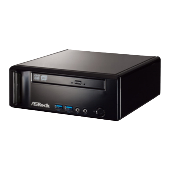
Mini Series 1.5 Front Panel No. Description Optical Disc Drive Power ON/OFF button with status indicator Drive activity indicator Headphone port Microphone port USB 3.0 ports: USB devices Infrared receiver... -
Page 15: Chapter 2 Quick Installation
Chapter 2 Quick Installation 1. Connect USB Devices to the USB Ports. 2. Connect a VGA Monitor to the VGA Port. 3. Connect the Network with the RJ-45 LAN Port. 4. Connect an HDMI Device to the HDMI Port. - Page 16 Mini Series 5. Connect a DVI Device to the DVI Port. 6. Connect an External Audio Device. (Line In Port for 2/4/6 Channel; Rear Port for 8 Channel) 7. Connect Stereo Speakers or Headphones. (Front L/R Out Port) 8. Connect a Microphone. (Mic In Port)
- Page 17 10. Connect Side Speakers. (Side Port for 4/6/8 Channel) 11. Connect an Optical Device to the Optical S/PDIF Out Port. 12. Connect Power to the DC-In Jack. 13. Power on the System. 14. Connect Headphones / Microphones / USB3.0 Devices...
-
Page 18: Chapter 3 Reinstalling The Odd/Hdd
Mini Series Chapter 3 Reinstalling the ODD/HDD 1. Remove the cover screws on the rear panel. (For safety reasons, please ensure that the power cord is disconnected before opening the case. 2. Slide the side cover toward the rear panel and pull the side cover upwards. - Page 19 4. Pull the ODD / HDD rack backwards and take it out from the bay. 5. Unscrew the screws from the side of the ODD / HDD rack, and change your required ODD / HDD. 6. Refer to the steps above to place the new ODD / HDD to the chassis. Replace the side cover and fasten the screws.
-
Page 20: Chapter 4 Installing The Second Hdd
Mini Series Chapter 4 Installing the second HDD 1. Please follow steps 1 to 4 above, and remove the ODD and the irst HDD in advance. hen fasten the screws of the second HDD to the rack. 2. Place the irst HDD to the rack and fasten the screws from both sides. - Page 21 4. Connect the SATA and power cables to the ODD and the bottom HDD. 5. Connect the other SATA and power cables to SATA3_M2 and J1 connectors on the motherboard. 6. Connect the other end to the top HDD. 7. Replace the side cover and fasten the screws.
-
Page 22: Chapter 5 Dual Monitor
With the internal VGA output which supports DVI-D, HDMI and D-Sub, you can enjoy dual monitor on your ASRock Mini series HTPC. ASRock Mini series HTPC also provides independent display controllers for DVI-D, HDMI and D-Sub to support dual VGA output so that DVI-D, HDMI and D-Sub can drive the same or diferent display contents simultaneously. -
Page 23: Chapter 6 Software And Utilities Operation
Chapter 6 Software and Utilities Operation 6.1 Installing Drivers he Support CD that comes with the motherboard contains necessary drivers and useful utilities that enhance the motherboard’s features. Running The Support CD To begin using the support CD, insert the CD into your CD-ROM drive. he CD automatically displays the Main Menu if “AUTORUN”... -
Page 24: A-Tuning
Mini Series 6.2 A-Tuning A-Tuning is ASRock’s multi purpose sotware suite with a new interface, more new features and improved utilities, including XFast RAM, Good Night LED, FAN- Tastic Tuning, and a whole lot more. 6.2.1 Installing A-Tuning When you install the all-in-one driver to your system from ASRock’s support CD, A-Tuning will be auto-installed as well. -
Page 25: System Info
XFast LAN Boost the speed of your internet connection! Select a speciic mode for making the designated program's priority highest. Good Night LED Switch of the Power/HDD LEDs when the system is on, and automatically switch of the Power and Keyboard LEDs when the system enters into Standby/Hibernation mode. - Page 26 Mini Series Settings Conigure ASRock A-Tuning. Click to select "Auto run at Windows Startup" if you want A-Tuning to be launched when you start up the Windows operating system.
-
Page 27: Intel® Smart Connect Technology
6.3 Intel® Smart Connect Technology Intel® Smart Connect Technology is a feature that periodically wakes your computer from Windows® sleep state to refresh email or social networking applications. It saves your waiting time and keeps the content always up-to-date. * Please note that the "Remote wake" feature of Intel® Smart Connect Technology is not supported. -
Page 28: Setup Guide
6.3.2 Setup Guide Installing ASRock Smart Connect Utility Step 1 Install ASRock Smart Connect Utility, which is located in the folder at the following path of the Support CD: \ ASRock Utility > Smart Connect. Step 2 Once installed, run ASRock Smart Connect from your desktop or go to Windows... - Page 29 Step 3 Click the Add button. Take Foxmail as an example, add Foxmail to the Application list. Step 4 Select Foxmail from the Application List, then click the arrow pointing right to add this application to the Smart Connect List. Step 5 Click Apply to enable Smart Connect.
-
Page 30: Using Smart Connect
Mini Series Step 6 Double-click the Intel® Smart Connect Technology Manager icon in the Windows system tray. Step 7 Drag the slider to conigure how oten the system will connect to the network to download updates. Shorter durations will provide more frequent updates, but may cause more power consumption. - Page 31 he system will wake up from sleep state periodically, and then start to update Foxmail. he screen will not display anything so the computer can maintain minimum power usage. Aterwards, the system will automatically return to sleep state again. Upon waking up the system, you will ind the new mail that were sent to you during sleep state are already updated and ready to be read in Foxmail.
-
Page 32: Asrock Cloud
ASRock Cloud includes several technologies and software solutions for remotely controlling your computer, even if the computer is in off mode. For ASRock motherboards with a Qualcomm® Atheros® LAN chip, ASRock Cloud allows users to remotely wake up their computers via the internet by using a secondary device, such as a smartphone or tablet. - Page 33 6.4.1 Qualcomm® Atheros® Security Wake On Internet Technology Qualcomm® Atheros® Security Wake On Internet Technology allows you to wake up and remote control your home computer from sleep or shutdown state. Before coniguring this feature, verify the followings on your host computer: •...
- Page 34 Mini Series 3.5.2 Coniguring and Using Orbweb.ME Professional Orbweb.ME Professional is a remote control sotware allowing you to easily access and control the remote host installed with the Orbweb.ME Professional host sotware. Installing Orbweb.ME Professional on the Host Computer You can find the Orbweb.ME Professional host software in the Support CD or just download it from http://orbweb.me.
- Page 35 Step 3 You will receive a veriication email. Follow the steps in the email to verify your account. Ater verifying your account, you can access your PC through web browsers at http://orbweb.me. On the Account Veriied page, if you click Go to My Computers, you will see the Orbweb. ME portal page as a client.
- Page 36 Mini Series REMOTE ACCESS FROM A CLIENT DEVICE he lastest version of Java is required to be installed to use the Remote Desktop and Xplorer functions. Using Remote Wake-Up Remote Wake-Up allows you to remotely put your host computer to sleep and wake your host computer up from a client device.
- Page 37 Step 4 Click and power options appear. Click to select Restart, Sleep or Shut Down. Select Restart from the options to restart your host computer remotely. When you select Sleep or Shut Down, if the host device is WOW(Wake-On-Wan) compatible, you can put your host computer to sleep (S3/S4) or shut down your host computer (S5) remotely.
-
Page 38: Using Remote Desktop
Mini Series Please be noted that if the host device is not WOW compatible, the host status icon will turn oline and the power option icon will dissappear. You have to physically wake up computer in order to bring power option icon back to online. - Page 39 For iOS or Android Mobile Devices users: Download and install “Orbweb.ME Professional” app from the App Store (iOS) or Play Store (Android). Step 1 Tap the “Orbweb.ME Professional” app icon to launch it. Step 2 Log in with your Orbweb.ME account and password. Step 3 Tap the host computer name that you want to access under the Remote Desktop section.
- Page 40 Mini Series Using Xplorer Xplorer allows you to remotely access documents on your host computer from a client device. For Windows PC users: Step 1 Go to Orbweb.ME portal login page http://orbweb.me Step 2 Log in with your Orbweb.ME account and password.
- Page 41 For iOS or Android Mobile Devices users: Download and install “Orbweb.ME Professional” app from the App Store (iOS) or Play Store (Android). Step 1 Tap the “Orbweb.ME Professional” app icon to launch it. Step 2 Log in with your Orbweb.ME account and password.
-
Page 42: Asrock App Shop
Double-click on your desktop to access ASRock APP Shop utility. *You need to be connected to the Internet to download apps from the ASRock APP Shop. 6.5.1 UI Overview Category Panel Hot News... -
Page 43: Apps
6.5.2 Apps When the "Apps" tab is selected, you will see all the available apps on screen for you to download. Installing an App Step 1 Find the app you want to install. he most recommended app appears on the let side of the screen. he other various apps are shown on the right. - Page 44 Mini Series Step 3 If you want to install the app, click on the red icon to start downloading. Step 4 When installation completes, you can ind the green "Installed" icon appears on the upper right corner. To uninstall it, simply click on the trash can icon...
- Page 45 Upgrading an App You can only upgrade the apps you have already installed. When there is an available new version for your app, you will ind the mark of "New Version" appears below the installed app icon. Step 1 Click on the app icon to see more details. Step 2 Click on the yellow icon to start upgrading.
-
Page 46: Bios & Drivers
Mini Series 6.5.3 BIOS & Drivers Installing BIOS or Drivers When the "BIOS & Drivers" tab is selected, you will see a list of recommended or critical updates for the BIOS or drivers. Please update them all soon. Step 1 Please check the item information before update. -
Page 47: Setting
6.5.4 Setting In the "Setting" page, you can change the language, select the server location, and determine if you want to automatically run the ASRock APP Shop on Windows startup. -
Page 48: Start8
6.6.1 Installing Start8 Install Start8, which is located in the folder at the following path of the Support CD: \ ASRock Utility > Start8. 6.6.2 Coniguring Start8 Style Select between the Windows 7 style and Windows 8 style Start Menu. hen select... - Page 49 Conigure Conigure provides coniguration options, including icon sizes, which shortcuts you want Start Menu to display, quick access to recently used apps, the functionality of the power button, and more. Control...
- Page 50 Mini Series Control lets you conigure what a click on the start button or a press on the Windows key does. Desktop Desktop allows you to disable the hot corners when you are working on the desktop. It also lets you choose whether or not the system boots directly into desktop mode and bypass the Metro user interface.
-
Page 51: Chapter 7 Uefi Setup Utility
Chapter 7 UEFI SETUP UTILITY 7.1 Introduction ASRock Interactive UEFI is a blend of system coniguration tools, cool sound efects and stunning visuals. Not only will it make BIOS setup less diicult but also a lot more amusing. his section explains how to use the UEFI SETUP UTILITY to conigure your system. -
Page 52: Navigation Keys
Mini Series 7.1.2 Navigation Keys Use < > key or < > key to choose among the selections on the menu bar, and use < > key or < > key to move the cursor up or down to select items, then press <Enter>... -
Page 53: Main Screen
7.2 Main Screen When you enter the UEFI SETUP UTILITY, the Main screen will appear and display the system overview. -
Page 54: Advanced Screen
Mini Series 7.3 Advanced Screen In this section, you may set the conigurations for the following items: CPU Coniguration, Chipset Coniguration, Storage Coniguration, Intel® Smart Connect Technology, ACPI Coniguration , USB Coniguration and Trusted Computing. Setting wrong values in this section may cause the system to malfunction. -
Page 55: Cpu Coniguration
7.3.1 CPU Coniguration Intel SpeedStep Technology Intel SpeedStep technology allows processors to switch between multiple frequencies and voltage points for better power saving and heat dissipation. CPU C States Support Enable CPU C States Support for power saving. It is recommended to keep C3, C6 and C7 all enabled for better power saving. -
Page 56: Chipset Coniguration
Mini Series 7.3.2 Chipset Coniguration DRAM Voltage (1.35V) Use this to conigure DRAM Voltage. he default value is [Auto]. Primary Graphics Adapter Select a primary VGA. Share Memory Conigure the size of memory that is allocated to the integrated graphics processor when the system boots up. - Page 57 Restore on AC/Power Loss Select the power state ater a power failure. If [Power Of] is selected, the power will remain of when the power recovers. If [Power On] is selected, the system will start to boot up when the power recovers. Good Night LED By enabling Good Night LED, the Power/LAN LEDs will be switched of when the system is on.
-
Page 58: Storage Coniguration
Mini Series 7.3.3 Storage Coniguration SATA Controller(s) Enable/disable the SATA controllers. SATA Mode Selection IDE: For better compatibility. AHCI: Supports new features that improve performance. AHCI (Advanced Host Controller Interface) supports NCQ and other new features that will improve SATA disk performance but IDE mode does not have these advantages. -
Page 59: Intel® Smart Connect Technology
7.3.4 Intel® Smart Connect Technology ® Intel Smart Connect Technology ® Intel Smart Connect Technology automatically updates your email and social networks, such as Twitter, Facebook, etc. while the computer is in sleep mode. -
Page 60: Acpi Coniguration
Mini Series 7.3.5 ACPI Coniguration Suspend to RAM Select disable for ACPI suspend type S3. It is recommended to select auto for ACPI S3 power saving. ACPI HPET Table Enable the High Precision Event Timer for better performance and to pass WHQL tests. -
Page 61: Usb Coniguration
7.3.6 USB Coniguration Intel USB 3.0 Mode Select Intel® USB 3.0 controller mode. Set [Smart Auto] to keep the USB 3.0 driver enabled ater rebooting (USB 3.0 is enabled in BIOS). Set [Auto] to automatically enable the USB 3.0 driver ater entering the OS (USB 3.0 is disabled in BIOS). Set [Enabled] to keep the USB 3.0 driver enabled (Must install driver to use USB devices under Windows®... -
Page 62: Trusted Computing
Mini Series 7.3.7 Trusted Computing Security Device Support Enable or disable BIOS support for security device. -
Page 63: Tools
Save UEFI iles in your USB storage device and run Instant Flash to update your UEFI. Internet Flash ASRock Internet Flash downloads and updates the latest UEFI irmware version from our servers for you. Please setup network coniguration before using Internet Flash. - Page 64 Mini Series Network Coniguration Use this to conigure internet connection settings for Internet Flash. Internet Setting Select an internet connection mode. UEFI Download Server Select a server to download the UEFI irmware.
-
Page 65: Hardware Health Event Monitoring Screen
7.5 Hardware Health Event Monitoring Screen his section allows you to monitor the status of the hardware on your system, including the parameters of the CPU temperature, motherboard temperature, fan speed and voltage. CHA Fan1 Setting Select a fan mode for Chassis Fan 1. Target CPU Temperature Select a target CPU temperature value. -
Page 66: Security Screen
Mini Series 7.6 Security Screen In this section you may set or change the supervisor/user password for the system. You may also clear the user password. Supervisor Password Set or change the password for the administrator account. Only the administrator has authority to change the settings in the UEFI Setup Utility. -
Page 67: Boot Screen
7.7 Boot Screen his section displays the available devices on your system for you to conigure the boot settings and the boot priority. Fast Boot Fast Boot minimizes your computer's boot time. In fast mode you may not boot from an USB storage device. Ultra Fast mode is only supported by Windows 8 and the VBIOS must support UEFI GOP if you are using an external graphics card. - Page 68 Mini Series Full Screen Logo Enable to display the boot logo or disable to show normal POST messages. CSM (Compatibility Support Module) Enable to launch the Compatibility Support Module. Please do not disable unless you’re running a WHCK test. If you are using Windows 8 64-bit and all of your...
-
Page 69: Exit Screen
7.8 Exit Screen Save Changes and Exit When you select this option the following message, “Save coniguration changes and exit setup?” will pop out. Select [OK] to save changes and exit the UEFI SETUP UTILITY. Discard Changes and Exit When you select this option the following message, “Discard changes and exit setup?”... -
Page 70: Contact Information
Mini Series Contact Information If you need to contact ASRock or want to know more about ASRock, you’re welcome to visit ASRock’s website at http://www.asrock.com; or you may contact your dealer for further information. For technical questions, please submit a support request form at http://www.asrock.com/support/tsd.asp...