
Related Manuals for Pentair FLECK 2750


Summary of Contents for Pentair FLECK 2750
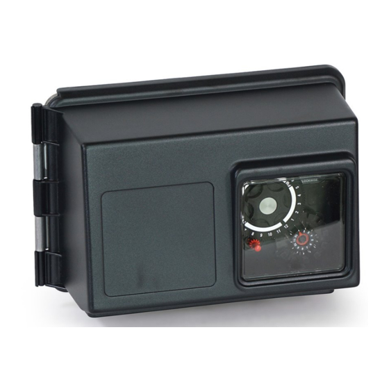
- Page 1 Get a Quote +1(714) 432-9996 Reverse Osmosis & Water Treatment Systems +1 (844) 309-7501 www.pureaqua.com FLECK 2750 DOWNFLOW SERVICE MANUAL...
-
Page 2: Table Of Contents
JOB SPECIFICATION SHEET TABLE OF CONTENTS Job Number: ______________________________________________ JOB SPECIFICATION SHEET ..........2 INSTALLATION ..............3 Model Number: ____________________________________________ Water Hardness: __________________________________ ppm or gpg START-UP INSTRUCTIONS ..........3 Capacity Per Unit: __________________________________________ 3200 TIMER SETTING PROCEDURE ........4 Mineral Tank Size: ___________ Diameter: ________Height: ________ 3210 TIMER SETTING PROCEDURE ........4 Salt Setting per Regeneration: ________________________________ 3200, 3210, 3220, 3230 REGENERATION CYCLE SETTING... -
Page 3: Installation
INSTALLATION 10. Place approximately 1 inch (25 mm) of water above the grid plate. If a grid is not utilized, fill to the top of the air check (Figure 1) in the salt tank. Do not add salt to the brine tank Water Pressure at this time. -
Page 4: Start-Up Instructions
INSTALLATION CONTINUED START-UP INSTRUCTIONS The water softener should be installed with the inlet, outlet, and Meter Dome and Union Orientation drain connections made in accordance with the manufacturer’s Control valves outfitted with an electromechanical timer and recommendations, and to meet applicable plumbing codes. stainless steel water meter include a special male x female 1. -
Page 5: 3210 Timer Setting Procedure
STARTUP INSTRUCTIONS CONTINUED 3210 TIMER SETTING PROCEDURE 5. In any event, conditioned water may be drawn after rinse Typical Programming Procedure water stops flowing from the water conditioner drain line. Calculate the gallon capacity of the system, subtract the How to Adjust Regeneration Time necessary reserve requirement and set the gallons available opposite the small white dot on the program wheel 1. -
Page 6: Regeneration Cycle Setting Procedure
3200, 3210, 3220, 3230 REGENERATION How To Change The Length Of Brine Tank Refill Time 1. The second group of holes in the program wheel determines CYCLE SETTING PROCEDURE the length of time that your water conditioner will refill the brine tank (2 min. - Page 7 [ THIS PAGE LEFT INTENTIONALLY BLANK ] FLECK • 7 2750 Downflow Service Manual...
-
Page 8: 3200 Time Clock Timer Assembly
3200 TIME CLOCK TIMER ASSEMBLY 61502-3200 Rev A 8 • FLECK 2750 Downflow Service Manual... - Page 9 3200 TIME CLOCK TIMER ASSEMBLY CONTINUED Item No. Part No. Description Item No. Part No. Description 30 ....1 ..13881 ....Bracket, Hinger Timer 1 ....1 ..13870 ....Housing, Timer, 3200 31 ....2 ..11384 ....Screw, Phil, 6-32 x 1/4 Zinc 2 ....1 ..
-
Page 10: 3210 Meter Delayed Timer Assembly
3210 METER DELAYED TIMER ASSEMBLY 61502-3210 Rev A 10 • FLECK 2750 Downflow Service Manual... - Page 11 3210 METER DELAYED TIMER ASSEMBLY Item No. Part No. Description 34 ....1 ..13902 ....Harness, 3200 CONTINUED 35 ....2 ..40422 ....Nut, Wire, Tan Item No. Part No. Description 36 ....1 ..15354-01 ..Wire, Ground, 4 inches 1 ....1 ..13870 ....Housing, Timer, 3200 37 ....1 ..
-
Page 12: 3220 Meter Immediate Timer Assembly
3220 METER IMMEDIATE TIMER ASSEMBLY 61502-3220 Rev B 12 • FLECK 2750 Downflow Service Manual... - Page 13 3220 METER IMMEDIATE TIMER ASSEMBLY CONTINUED Item No. Part No. Description Item No. Part No. Description 35 ...17 ..41754 ....Pin, Spring, 1/16 x 5/8 1 ....1 ..13870 ....Housing, Timer Stainless Steel, Timer 2 ....1 ..15431 ....Gear, Cycle Actuator, 36 ....1 ..
-
Page 14: 3230 Remote Start Timer Assembly
3230 REMOTE START TIMER ASSEMBLY 61502-3230R REV A 14 • FLECK 2750 Downflow Service Manual... - Page 15 3230 REMOTE START TIMER ASSEMBLY CONTINUED Item No. Part No. Description Item No. Part No. Description 1 ....1 ..13870 ....Housing, Timer 22 ....1 ..13011 ....Cycle Actuator Arm 2 ....1 ..14265 ....Spring Clip 23 ....1 ..13881 ....Bracket, Hinge Timer 3 ....3 ..
-
Page 16: Powerhead Assembly (Environmental)
POWERHEAD ASSEMBLY (ENVIRONMENTAL) BR61501-1500 Rev C 16 • FLECK 2750 Downflow Service Manual... - Page 17 POWERHEAD ASSEMBLY (ENVIRONMENTAL) CONTINUED Item No. Part No. Description Item No. Part No. Description 17 ....1 ..17421 ....Plug, 1.20 Hole 18697-15 Backplate, Hinged 18 ....2 ..19691 ....Plug, .750 Dia. Hole, Flush 2 ....1 ..11838 ....Power Cord, 6-foot, North American, Flat 19 ....7 ..
-
Page 18: Manual Powerhead Assembly
MANUAL POWERHEAD ASSEMBLY 60409 Rev A Item No. Part No. Description 1 ....1 ..12593 ....Backplate, Manual 2 ....1 ..12592 ....Bracket, Lever Position 3 ....1 ..12596 ....Screw, Spec Mach, 1/4 - 20 x 1/2 4 ....1 ..12707 ....Washer, Spring 5 ....1 .. -
Page 19: Control Valve With 1700 Injector Assembly
CONTROL VALVE WITH 1700 INJECTOR ASSEMBLY 60036 Rev C FLECK • 19 2750 Downflow Service Manual... - Page 20 CONTROL VALVE WITH 1700 INJECTOR CONTINUED Item No. Part No. Description Item No. Part No. Description ..10914-1 ..Throat, Injector, #1, White 1 ....1 ..14749 ....Valve Body, 2750 ..10914-2 ..Throat, Injector, #2, Blue 2 ....6 ..10545 ....Seal, Piston 3 ....5 ..
- Page 21 CONTROL VALVE WITH 1700 INJECTOR CONTINUED Item No. Part No. Description Item No. Part No. Description 28 ....2 ..10692 ....Screw, Slot Hex Hd, ..60365-24 ..DLFC, 3/4-inch F x 1/2-inch F, 10-24 x 18-8 Stainless Steel NPT 2.4 gpm 29 ....1 ..
-
Page 22: Softener Filter Conversion Kits
SOFTENER FILTER CONVERSION KITS 61671 Rev E Item No. Part No. Description 1 ....... 61671-02 ..NHWBP Conversion Kit, 2510 22 • FLECK 2750 Downflow Service Manual... -
Page 23: 1600 Brine System Assembly
1600 BRINE SYSTEM ASSEMBLY 60029 Rev C Item No. Part No. Description Item No. Part No. Description 14 ....1 ..11982 ....O-ring, -016 1 ....2 ..10332 ....Fitting, Insert, 3/8 15 ....1 ..60020-25 ..BLFC, .25 GPM, 1600 2 ....1 ..12767 ....Screen, Brine .. -
Page 24: 1650 Brine System
1650 BRINE SYSTEM 60011 Rev D Item No. Part No. Description Item No. Part No. Description 19 ..... 60010-25 BLFC Assy. (Parts) 1 ....1 ..10328 ....Elbow, 90 1/4 NPT x 3/8 1 ..17907 ....Housing 3 ....3 ..10332 ....Insert, 3/8 1 .. -
Page 25: 1700 Series Brine System Assembly
1700 SERIES BRINE SYSTEM ASSEMBLY Item No. Part No. Description Item No. Part No. Description 18 ....1 ..60034-00 ..Brine Valve, 1700, Blank 1 ....1 ..14792 ....Plug, End, Brine Valve ..60034-10 ..Brine Valve, 1700, 1.0 gpm 2 ....1 ..13201 ....Quad Ring, -020 .. -
Page 26: 1710 Brine System Assembly
1710 BRINE SYSTEM ASSEMBLY 60604 Rev F Item No. Part No. Description Item No. Part No. Description ..15416 ....Tube, Brine, 2900/2750 1 ....1 ..41202 ....Brine Valve, 1700, Plastic, ..41447* ....Tube, Brine, 2900s U/F 21 ....1 ..15413 ....Fitting, Elbow, Male, 2 ....1 .. - Page 27 1-INCH BRASS METER ASSEMBLY Item No. Part No. Description Item No. Part No. Description 15 ..... 60392 ....Meter Assy, 1-inch Inline, 1 ....4 ..12112 ....Screw, Slotted Hex Head, NPT EXT Range #10 - 24 x .50 ..60392NP ..Meter Assy, 1-inch 2 ....1 ..
- Page 28 1-INCH STAINLESS STEEL METER ASSEMBLY IMPORTANT: For valves equipped with electromechanical timers and stainless steel meters, refer to the Meter Dome and Union Orientation section. Item No. Part No. Description 1 ....1 ..62049-01 ..Service Kit, 1 inch & 1-1/2 inch Meter, Standard Range 1 ..
-
Page 29: 1600 Service Valve Operator (New Style)
1600 SERVICE VALVE OPERATOR (NEW STYLE) 60150 Rev A Item No. Part No. Description 1 ....1 ..11749 ....Guide, Brine Valve Stem 2 ....1 ..10250 ....Ring, Retaining 3 ....1 ..10249 ....Spring, Brine Valve 4 ....1 ..12550 ....Quad Ring, -009 5 ....2 .. -
Page 30: 2300 Safety Brine Valve
2300 SAFETY BRINE VALVE 60027 Rev D Item No. Part No. Description Item No. Part No. Description ..60002-36 ..Air Check, #500, 36 inches 1 ....1 ..60027-00 ..Safety Brine Valve, 2300, Less Long Elbow ..60002-48 ..Air Check, #500, 48 inches 2 ....1 .. -
Page 31: 2310 Safety Brine Valve
2310 SAFETY BRINE VALVE Item No. Part No. Description Item No. Part No. Description ..60068-30 ..Float Assy, 2310, w/30-inch 1 ....1 ..19645 ....Body, Safety Brine Valve, 2310 14 ....1 ..60002-10 ..Air Check, #500, American 2 ....1 ..19803 ....Safety Brine Valve Assy Hydro 3 ....1 .. -
Page 32: 2350 Safety Brine Valve Assembly
2350 SAFETY BRINE VALVE ASSEMBLY 42303 REV A Item No. Part No. Description 1 ....1 ..60038 ....Safety Brine Valve, 2350 1A ....1 ..61024 ....Actuator Assembly, 2350 Brine 2 ....1 ..60028-30 ..Float Assembly, 2350, 30- inch Wht ..60026-30SAN .Float Assembly, 2350, 30- inch , HW 3 ....1 .. -
Page 33: 2750 Control Valve Dimensions
2750 CONTROL VALVE DIMENSIONS 2750 MODEL WITH 1700 BRINE SYSTEM 88.1 3.47 241.7 9.52 181.3 162.5 7.14 155.8 6.14 288.9 11.37 8.66 219.6 8.65 157.3 6.19 5.28 156.7 6.17 320.6 12.62 2750 MODEL WITH 1600 BRINE SYSTEM 259.5 10.22 128.6 5.06 4.18 BR61500-2750LNE Rev B... -
Page 34: Troubleshooting
TROUBLESHOOTING Problem Cause Correction Water conditioner fails to Electrical service to unit has been Assure permanent electrical service (check fuse, regenerate. interrupted plug, pull chain, or switch) Timer is defective. Replace timer. Power failure. Reset time of day. Hard water. By-pass valve is open. -
Page 35: General Service Hints For Meter Control
GENERAL SERVICE HINTS FOR METER CONTROL Problem: Softener delivers hard water Reason: Reserve capacity has been exceeded. Correction: Check salt dosage requirements and reset program wheel to provide additional reserve. Reason: Program wheel is not rotating with meter output. Correction: Pull cable out of meter cover and rotate manually. Program wheel must move without binding and clutch must give positive clicks when program wheel strikes regeneration stop. -
Page 36: Water Conditioner Flow Diagrams
WATER CONDITIONER FLOW DIAGRAMS 1 Service Position 4 Slow Rinse Position 2 Backwash Position 5 Rapid Rinse Position 3 Brine Position 6 Brine Tank Fill Position 36 • FLECK 2750 Downflow Service Manual... -
Page 37: Flow Data & Injector Draw Rates
FLOW DATA & INJECTOR DRAW RATES FLECK • 37 2750 Downflow Service Manual... -
Page 38: System #4
SYSTEM #4 SYSTEM #6 Typical Tank Installation with Optional Meter Twin Series Regeneration Installation with a Remote Meter SYSTEM #7 Twin Alternator Installation with a Remote Meter SYSTEM #5 INTERLOCK Typical Twin Tank Installation with Optional 2 Meter Interlock and No Hard Water Bypass 38 •... -
Page 39: System #4 Immediate & Delayed Valve Wiring
SYSTEM #4 IMMEDIATE & DELAYED VALVE WIRING FLECK • 39 2750 Downflow Service Manual... -
Page 40: System #4 Remote Signal Start Valve Wiring
SYSTEM #4 REMOTE SIGNAL START VALVE WIRING 40 • FLECK 2750 Downflow Service Manual... -
Page 41: System #5 Duplex Valve Wiring
SYSTEM #5 DUPLEX VALVE WIRING 40502-01 REV C 40502-02 REV C FLECK • 41 2750 Downflow Service Manual... -
Page 42: System #6 Duplex Valve Wiring
SYSTEM #6 DUPLEX VALVE WIRING 13632-01 REV L 13632-02 REV L 42 • FLECK 2750 Downflow Service Manual... -
Page 43: System #7 Duplex 24V/120V 3-Way Valve Wiring
SYSTEM #7 DUPLEX 24V/120V 3-WAY VALVE WIRING 19138-01 REV E 19138-02 REV E FLECK • 43 2750 Downflow Service Manual... -
Page 44: System #7 Duplex 230V 3-Way Valve Wiring
SYSTEM #7 DUPLEX 230V 3-WAY VALVE WIRING 17727-01 REV E 17727-02 REV E 44 • FLECK 2750 Downflow Service Manual... -
Page 45: Service Assemblies
SERVICE ASSEMBLIES Piston, Seal, and Spacer Kits: 24 Hour Gear Assembly: 61670-01 ��������������������� Piston Kit, 2750/2750 19205 ��������������������������� Gear Assy, 24 Hour, Silver, 5600, 12AM 61670-02 ��������������������� Piston Kit, 2510, 2750, NHWBP 60519-02 ��������������������� Gear Assy, 24 Hour, 2 Times a Day Regen 60519-03 ���������������������... - Page 46 46 • FLECK 2750 Downflow Service Manual...
- Page 47 FLECK • 47 2750 Downflow Service Manual...
- Page 48 For a detailed list of where Pentair trademarks are registered, please visit waterpurification.pentair.com/brands. § Pentair trademarks and logos are owned by Pentair plc or its affiliates. Third party registered and unregistered trademarks and logos are the property of their respective owners.