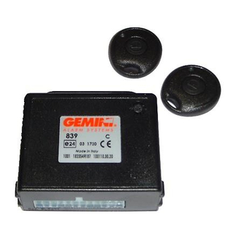
Summary of Contents for Gemini 839 Series
- Page 1 INSTALLATION AND USE MANUAL Reg. n.532-A UNI EN ISO 9001:2008 AC 2729/UK Rev. 00 - 06/10 Made in Italy...
-
Page 2: Table Of Contents
TABLE OF CONTENTS - PRELIMINARY ADVICE..................... PAGE 02 USER MANUAL - OPERATING DESCRIPTION..................PAGE 03 2.1 - Vehicle CDL locking....................PAGE 03 2.2 - Vehicle CDL locking and comfort control..............PAGE 03 2.3 - Vehicle CDL unlocking....................PAGE 03 - REMOTE CONTROL BATTERIES REPLACEMENT..........PAGE 03 INSTALLER MANUAL PAGE 04... -
Page 3: User Manual
USER MANUAL 2.0 - OPERATING DESCRIPTION This manual also refers to the LED and to its various optical signals. The LED is optional and therefore not included in the kit. 2.1 - VEHICLE CDL LOCKING Press the button on the remote control; the LED will light up steady for 10”... -
Page 4: Installer Manual
INSTALLER MANUAL 4.0 - CONNECTOR TABLE WIRE COLOUR POSITION WIRE FUNCTION - 1 - ------- ------- - 2 - Doors push-button input GREEN-BROWN - 3 - Positive under key YELLOW - 4 - ------- ------- - 5 - ------- ------- - 6 - Power supply ground BROWN... -
Page 5: Complete Electric Diagram
5.0 - COMPLETE ELECTRIC DIAGRAM Before carrying out all electrical connections, disconnect the negative battery terminal and re- connect again after completion. KIT2322NF KIT2323S BLACK Antenna, do not tamper POSITIVE Battery BROWN GROUND Black RED-GREY It is reccomended to use a 10A fuse RED-BROWN RED-BLUE YELLOW-BLUE... -
Page 6: Add New Devices
6.0 - ADD NEW DEVICES In order to carry out successfully the operation, it is necessary to make the required electrical connections (door switch and positive under key). The system can learn up to 50 remote controls. For procedure activation follow the indications reported below. With the system being disarmed, open and keep opened vehicle driver side door. -
Page 7: Deletion Of Programmed Devices
7.0 - DELETION OF PROGRAMMED DEVICES In order to carry out successfully the operation, it is necessary to make the required electrical connections (door switch and positive under key). The system includes a devices deletion procedure. PFor procedure activation follow the indications reported below. With the system being disarmed, open and keep opened vehicle driver side door. -
Page 8: Programmabe Functions Description
Do not modify the functions which have been programmed during the installation ntering the programming procedure resets the functions to the default Setting The system has a “standard configuration” programmed during manufacturing procedure by Gemini. For programming modification proceed as follows With the system disarmed and doors closed, turn the vehicle ignition key to “ON”... -
Page 9: Warranty Conditions
The warranty will become void if labels are missing or torn, if the installation certificate is not fully compiled or if the enclosed sale document is missing. The guarantee is valid exclusively at authorized Gemini Technologies S.p.A. Service Centers. The manufacturer declines any responsibility for eventual malfunctions of the device or any damage to the vehicle electrical system due to improper installation, use or tampering. - Page 10 A, B, D, DK, F, FR, GR, IR, I, L, NL, P, Il prodotto può essere immesso nei seguenti Stati Europei: SP, S, UK Company responsible for placing on the market: GEMINI TECHNOLOGIES S.p.A. Società responsabile per l’immissione nel mercato: Address: Via Luigi Galvani 12 - 21020 BODIO LOMNAGO (VA) -...
- Page 11 7 Dudley Court , Jessop Close, Clacton-on-Sea, Essex, CO15 4LY TEL: +44 (0) 1255 434353 Email: sales@avsgemini.com | Web: www.avsgemini.com UK Distributors of the Gemini Alarm Systems...


