Table of Contents
Advertisement
Quick Links
Advertisement
Table of Contents

Related Manuals for PSC LM520


Summary of Contents for PSC LM520
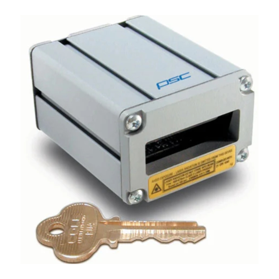
- Page 1 LM520 Scanner Integration & Programming Manual R44-2016 (Rev. E)
-
Page 2: Table Of Contents
Contents The LM520 Bar Code Scanner Overview .................................1 Unpacking the LM520............................. 2 Scanner Care ..............................2 Mounting the LM520 General Considerations ..........................3 Mounting .................................3 Mounting the Scanner Stand-Alone........................ 4 Integrating the Scanner to Read at the Proper Distance ................4 Integrating the Scanner Behind a Window .....................5 Electrical Interface ............................8... - Page 3 No Read Output Signal Mode 2 ......................37 Diagnostic Commands ...........................38 Good Read LED Duration ........................38 Appendix A:Technical Specifications ......................A-1 Appendix B: Mechanical Specifications .......................B-1 Appendix C: Factory Default Configuration ....................C-1 Appendix D: LM520 Programming Labels ....................D-1 Appendix E: ASCII Conversion Table ......................E-1 R44-2016...
- Page 4 List of Tables Table 1. Electrical Interface Specifications ..................8 Table 2. Configuration Commands .....................10 Table 3. Baud Rate ..........................14 Table 4. Data Format ..........................15 Table 5. Flow Control .........................16 Table 6. Software Switch Control .......................17 Table 7. Hardware Switch Control .....................18 Table 8.
-
Page 5: The Lm520 Bar Code Scanner
In some cases the data may be processed further by the scanner before being transmitted to the host. The LM520 has four different operational modes which can be used to scan a bar code. The four operational modes include: •... -
Page 6: Unpacking The Lm520
The LM520 Bar Code Scanner Section 1 Unpacking the LM520 The LM520 bar code scan scanner is shipped in custom packaging. Carefully open the package, and remove the scanner from the packing material. The LM520 standard configuration includes: • LM520 scanner •... -
Page 7: Mounting The Lm520
Section 2 Mounting the LM520 The LM520 bar code scanner is designed to be mounted to a stand in a fixed position. This section describes the layout of the mounts for optimum scanner performance. General Considerations Although the LM520 bar code scanner has been designed to be impact-resistant, it is impor- tant to consider the effect of the environment on the scanner. -
Page 8: Mounting The Scanner Stand-Alone
Integrating the Scanner to Read at the Proper Distance When deciding how to mount the LM520, there are many criteria that must be considered. First, there are minimum and maximum distances that the bar code can be from the front of the scanner to properly read, depending on the size of the bar code. -
Page 9: Integrating The Scanner Behind A Window
The LM520 scanner emits a laser beam in the form of a scan line. The beam’s light exits the scanner’s window and reflects off the bar code symbol. The reflected light returns through the window, and is collected with a photodiode. - Page 10 Figure 3. Tilt Angle Reflected light 0.880" 22.34mm Angle = 103.7˚ Window 0.125" Nominal 3.18mm Beam Path 0.820" 20.83mm d = 1.250" 31.74mm ( )] 0.65 Angle = 90 + 0.5 arctan = 103.7 1.25 LM520 Scanner Integration & Programming Manual...
- Page 11 Section 2 Mounting the LM520 An example of acceptable system window inclination is shown in Figure 2. As can be seen, moving the system window closer to the scanner makes it necessary to increase the window angle with respect to vertical. Less inclination is necessary if the reflection is directed below, rather than above the scanner, since laser light is emitted near the bottom of the scanner’s...
-
Page 12: Electrical Interface
Mounting the LM520 Section 2 Electrical Interface The LM520 scanner communicates with the host over a standard DB-9 connector. The pinouts for the connector are shown in Table 1. Table 1. Electrical Interface Specifications Direction Pin # Signal Function (relative to... -
Page 13: Interface Cable Schematic
Section 2 Mounting the LM520 Interface Cable Schematic The drawing in Figure 4 shows a schematic view of the electrical connection between the scanner and the host. Figure 4. Interface Cable Schematic DB9-P DB25-S BEEPER/GOOD READ ORANGE Power Supply YELLOW 4.75 - 12VDC... -
Page 14: Lm520 Scanner Configuration
Active configuration. See Appendix C, Factory Default Configura- tion for a concise list of the factory defaults. The LM520 offers the ability to change and save a new Factory Default configuration. To overwrite the Factory Default configuration as shipped from PSC, first make changes to the Active Configuration, then store the Active Configuration as the Factory Default. - Page 15 Section 3 LM520 Scanner Configuration Figure 5. Configuration Management Factory Default Configuration Active Configuration Host Serial Command Programming Label Z1 - Copy vaulted configuration into active configuration. Z2 - Copy configuration from active configuration to the factory default configuration. R44-2016...
-
Page 16: Programming Methods
Section 3 Programming Methods The LM520 scanner may be programmed either by sending commands from a host over the serial interface or by the using bar codes containing programmable commands. Typically, the scanner is programmed over the serial interface when it is integrated into a system. -
Page 17: Programming With Bar Codes
LM520 Scanner Configuration Programming with Bar Codes The LM520 scanner can also be programmed by scanning bar codes which contain com- mands. This method allows users to easily adjust scanner parameters. Bar codes used for programming must be Code 128, with a Function Code 3 (FNC3) as the first character. -
Page 18: Setting Serial Communication Parameters
RS-232 communication settings. Baud Rate Use one of the commands shown in Table 3 to set the LM520 baud rate. Note that the scan- ner and the host must communicate at the same rate for communication to be successful. An ACK command will be sent by the scanner at the new baud rate, indicating that the com- mand has been received and understood. -
Page 19: Data Format
LM520 Scanner Configuration Data Format These parameters control the data format in which the LM520 will communicate with the host. Note that the scanner and host must communicate in the same format for communica- tion to be successful. An ACK command will be sent by the scanner in the new format indi- cating that the command has been received and understood. -
Page 20: Flow Control
Section 3 Flow Control As shown in Table 5, the LM520 scanner supports standard flow control protocols, including XOn/XOff (software flow control) and CTS/RTS (hardware flow control). If CTS/RTS is being used, first send the HA command before sending a new Flow Control command (HB - HN). -
Page 21: Controlling Scanning Through Host Commands
Scan Now. Begin scanning immediately. Scan until a bar code is decoded, or for a maximum of XX scans. (01-99) NOTE: The LM520 scans approximately 42 times per second. Scan Now. Begin scanning immediately. Scan until a bar code is decoded, or until the scanning timeout expires. See BH command in Table 30. -
Page 22: Triggering Scanning Using Hardware Switch
Hardware scanning continues until either the Scan Trigger is deasserted or until the scanner timeout expires. See BH command in Table 30. Continuous Scanning Mode The LM520 may also be set for Continuous Scanning mode through host commands. Table 8. Continuous Scanning Mode Command... -
Page 23: Lasersense Scanning Mode
ND or NB labels. The ASCII DC4 command is a single byte (0x14 hex) and should not be sent with a STX-ESC preceding it. When the LM520 receives this single char- acter, it will respond with an ACK, turn active scanning off and be ready to receive addi- tional programming commands. -
Page 24: Setting Symbology Parameters
Section 3 Setting Symbology Parameters The LM520 is able to decode UPC-A, UPC-E, EAN-8, EAN-13, Code 39, Code 128, Code 93, Codabar, Interleaved 2 of 5, and Standard 2 of 5 symbologies. The decoder will actively attempt to match bar code data against all symbologies which are enabled. Thus, perfor- mance is enhanced by disabling symbologies which are not used in a particular environ- ment. -
Page 25: Ean
Section 3 LM520 Scanner Configuration Table 11. EAN Command Parameter Setting Disable EAN-13 Enable 2 and 5 digit supplementals for EAN-13 and EAN-8. RC * Enable EAN-13 Disable EAN-8 RP * Enable EAN-8 Disable all EAN 2 and 5 digit supplementals (EAN-8, EAN-13). -
Page 26: Code 128
FNC1 = 80h, FNC2 = 81h, FNC3 = 82, FNC4 = 83h FNC3 = in the first data position of a Code 128 bar code is reserved for programming labels and no data will be transmitted to the host from a programming label. NOTE LM520 Scanner Integration & Programming Manual... -
Page 27: Code Isbt 128
Section 3 LM520 Scanner Configuration Code ISBT 128 ISBT 128 is a bar code symbology for labeling of whole blood and blood components adopted by the International Council for Commonality in Blood Banking Automation. (ICCBBA). Implementation of ISBT 128 requires the payment of a registration fee and an annual license fee thereafter. -
Page 28: Table 15. Concatenation Pairs
Disables the specially programmed concatenated ISBT 128 labels, if defined. To again read specially pro- grammed concatenated ISBT 128 labels, use TR command followed by the special programming label. See the specification for ISBT 128 from ICCBBA for creating specially programmed concatenated bar codes. LM520 Scanner Integration & Programming Manual... -
Page 29: Code 93
Section 3 LM520 Scanner Configuration Code 93 When Code 93 is enabled, the bar code length defaults are set to zero which allows the scan- ner to read Code 93 bar codes of varying lengths up to 50 characters. If the scanner will be used for specific fixed length bar codes, use the UE and UF commands to enable these fixed lengths. -
Page 30: Code 39
If set to 00, the scanner ignores the min/max settings. Set maximum data characters to XX characters. Includes start/stop characters and check characters, if (00 -46) transmitted. Enable transmission of the check character OK * Disable transmission of the check character LM520 Scanner Integration & Programming Manual... -
Page 31: Interleaved 2 Of 5
Section 3 LM520 Scanner Configuration Interleaved 2 of 5 When Interleaved 2 of 5 is enabled, the default bar code length is fixed at 14 characters (PD14 & PE14). Table 20. Interleaved 2 of 5 Command Parameters Setting PA * Disable Interleaved 2 of 5. -
Page 32: Standard 2 Of 5
Set maximum length for Standard 2 of 5 to XX characters. (04 - 48) PV * Disable transmission of Standard 2 of 5 check digit. Enable transmission of Standard 2 of 5 check digit. LM520 Scanner Integration & Programming Manual... -
Page 33: Formatting Bar Code Data
Section 3 LM520 Scanner Configuration Formatting Bar Code Data Bar code data can be returned to the host as raw bar code data or additional characters may be appended before or after the bar code data, or the bar code data may be truncated and reformatted to meet the needs of the host. -
Page 34: Filters
Section 3 Filters After the bar code is decoded, the LM520 scanner may apply a filter on the decoded data before transmitting the data to the host. A filter is maintained for each symbology the scan- ner supports. All bar codes using a given symbology are processed using the filter for that symbology. -
Page 35: Field Descriptions
Section 3 LM520 Scanner Configuration Figure 6 shows an example of fully appended bar code data that would be sent from the scanner to the host. To set a filter for a particular symbology, use the command below. Note that the filter must be provided as a parameter. If no filter is provided, the scanner will return no data. -
Page 36: Table 25. Symbology Identifiers
Table 25. Symbology Identifiers Symbology Identifier UPC-A ‘d’ UPC-E ‘d’ EAN-13 ‘d’ EAN-8 ‘d’ Code 39 ‘a’ ‘b’ ‘c’ Codabar ‘h’ Code 93 ‘g’ Code 128 ‘f’ Code ISBT128 ‘f’ LM520 Scanner Integration & Programming Manual... -
Page 37: Pad Character
Section 3 LM520 Scanner Configuration Pad Character Valid pad characters are N, S and Z as shown below. Table 26. Pad Characters Do not fill Pad with spaces Pad with zeroes Edit Function Edit functions may be one of: Table 27. Edit Functions Include the last ‘n’... -
Page 38: Setting The Bar Code Format
For example, a complete command to set the bar code filter to return the literal ‘12’, the bar code data, then the literal ‘34’ for UPC-A bar codes is: FC12%D%34 The command to set the same filter for UPC-E bar codes is: FD12%D%34 LM520 Scanner Integration & Programming Manual... -
Page 39: Additional Commands
NOTE Laser Timeout If a bar code is not read and decoded successfully within a certain period of time, the LM520 will stop scanning. The length of time the scanner remains active before timing out can be set to between 0.1 and 9.9 seconds. This command affects hardware, software and LaserSense triggering modes. -
Page 40: Double Read Timeout
= 600 ms. Read Verification When the Read Verification feature is used, the LM520 will not consider a bar code to be suc- cessfully decoded until it has obtained the same results from scanning the bar code on mul- tiple attempts. -
Page 41: No Read Message
NOTE No Read Output Signal The LM520 No Read signal is output on pin 4 of the 9 pin DSUB connector. This signal is an active low signal (0 V) input to a PLC (Programmable Logic Controller). The normal signal is high (5VDC). -
Page 42: Diagnostic Commands
Disable No Read Timeout Mode 2. NL * Returns signal to +5VDC Diagnostic Commands The LM520 scanner provides commands which allow testing of the scanner, and provide information about the firmware in the scanner. Table 35. Diagnostic Commands Command Settings Display operational software version. -
Page 43: Appendix A:technical Specifications
Appendix A:Technical Specifications Table A-1. Performance Specifications Parameter Specification Scan Rate 42 scans/second ± 10% (bi-directional) Scan Angle 46° nominal, ±2.0° Vertical Beam Pointing 0° nominal, ±2.0° (relative to mounting surface) 88.3° nominal, ±4° (toward right from engine perspective, relative to Horizontal Beam Pointing engine front face) Vertical Beam Exit Position... -
Page 44: Table A-2. Power Requirements
Rain and Dust IP54 Table A-4. Agency Approvals Laser Output Power 1.26 mW ±6% Laser Safety CDRH Class II, IEC 825 Class 2 EMI/RFI FCC-A, EN55022-B, UCCI-B, AS/NZ 3450 Safety Conformity UL, TÜV, CUL, GOST-R LM520 Scanner Integration & Programming Manual... -
Page 45: Appendix B: Mechanical Specifications
Appendix B: Mechanical Specifications 2.00" (5.08cm) 2.53" (6.34cm) 0.086" (21.84cm) 0.088" (22.34cm) 88.3˚±2.0˚ 23.0˚ ±2.0˚ 23.0˚ ±2.0˚ 0.53" (13.46cm) 1.35" (3.43cm) 0.820" (20.83cm) 90˚±1.5˚ R44-2016... -
Page 46: Appendix C: Factory Default Configuration
Disable transmission of the Code 39 check character Disable Interleaved two of five Disable transmission of Interleaved 2 of 5 check digit Disable Standard two of five (STF) Disable transmission of STF check digit LM520 Scanner Integration & Programming Manual... - Page 47 Description Enable UPC-A Disable expansion of UPC-E Enable UPC-E Disable all UPC 2 and 5 digits supplementals (UPC-A, UPC-E) QY15 Number of scanning retries to build UPC/EAN supplementals = 15 Enable EAN-13 Enable EAN-8 Disable all EAN 2 and 5 digit supplementals (EAN 8, EAN13) Enable Code 128 Disable transmission of Code 128 function codes Disable Code 93...
-
Page 48: Appendix D: Lm520 Programming Labels
LM520 Programming Labels The most common method of configuring the LM520 scanner is by sending commands from the host. (see Configuration of the LM520). The bar codes contained in this table are a limited set of the programmable options. Table D-1. Programming Labels... - Page 49 Programming Labels (continued) Feature Code Bar Code Set beeper duration to AE03 135ms ³ Set scanner timeout to BH60 6.0 seconds ³ Set scanner timeout to BH99 9.9 seconds ³ Set scanner to no timeout BH00 until bar code is decoded ³...
-
Page 50: Appendix E: Ascii Conversion Table
Appendix E: ASCII Conversion Table Table E-1. ASCII Conversion Table CHAR CHAR CHAR NULL < > “ & ‘ LM520 Scanner Integration & Programming Manual...