Table of Contents
Advertisement
Quick Links
Advertisement
Table of Contents

Related Manuals for PSC PowerScanTM RF


Summary of Contents for PSC PowerScanTM RF
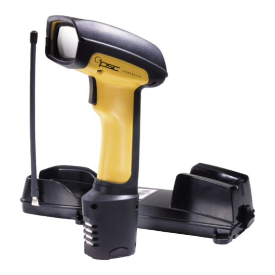
- Page 1 PowerScan™ RF Handheld Bar Code Scanner User’s Guide...
- Page 2 All rights reserved. No part of the contents of this documentation or the procedures described therein may be reproduced or transmitted in any form or by any means without prior written permission of PSC Inc. Owners of PSC Inc.'s products are hereby granted non-exclusive, revocable license to reproduce and transmit this documentation for the purchaser's own internal business purposes.
-
Page 3: Table Of Contents
Installing the Battery ... 2 Verifying Scanner Operation ... 3 Connecting the Base Station to the Host Terminal... 3 Linking the Scanner to a Base Station ... 5 Verifying Scanner-to-Base Station Communications... 6 Using the PowerScan RF System... 7 Battery Charging and Maintenance ... 7 Tips for Extending Battery Life ... -
Page 4: Unpack And Inspect Your Scanner
Quick Start Instructions The basic steps below must be performed to set up the RF scanner. Each of these steps is detailed in this manual. •... -
Page 5: Installing The Battery
Charging and Maintenance on page 7.) NOTE Orient the battery as shown in Figure 1, then push it into the scanner until it snaps in place. To remove the battery, push in on the release tabs on both sides of the battery’s base and pull it straight out of the scanner. -
Page 6: Verifying Scanner Operation
Base Station are programmed to respond (see LED and Beeper Indications for details). If your scanner fails to read a sample bar code of a symbology it’s programmed to read, turn to the section titled, Troubleshooting. - Page 7 Host Terminal (e.g., baud rate, parity, etc.) and, if necessary, modify the pro- grammed parameters to be compatible with those require- ments. Scanner and Base Station programming is performed using one of the following: - Configurator Express™ Programming Software - PowerScan™...
-
Page 8: Linking The Scanner To A Base Station
Linking the Scanner to a Base Station To link a scanner to a Base Station, simply scan the Base Station ID bar code located on the top of the desired Base Station. As the scanner searches for the Base Station, a short beep is heard as it seeks for the correct channel. -
Page 9: Verifying Scanner-To-Base Station Communications
Verifying Scanner-to-Base Station Communications Point the linked scanner at a sample bar code from the back pages of this manual, and pull the trigger (see How to Scan for tips on scanning bar codes). Watch the TX/RX (transmit/receive) indicator LED on the Base Station and/or scanner green LED while scanning the bar code. -
Page 10: Using The Powerscan Rf System
NOTE and Beeper Indications for more information. Seat the scanner in the Base Station as shown in Figure 4, ensuring that the battery fully engages the station’s metal contacts. The CHARGE LED on the Base Station should flash, indicating the bat- tery is charging. -
Page 11: Tips For Extending Battery Life
If a battery is removed from the scanner and stored, it should be fully charged when stored. Batteries will lose the ability to hold a charge when stored for long periods of time (weeks, months, or longer). -
Page 12: Four Station Charger
Four Station Charger If you have a Four Station Charger, batteries are inserted for charging as shown in Figure 5. A 90% rapid charge can be achieved in only two hours when using this optional accessory, half the time than when a Base Station is used for charging. -
Page 13: How To Scan
Figure 6 illustrates some tips to help get the best scanning results: The scanner must be pointed at a slight angle to the bar code. Do not hold the scanner perpendicular to the bar code. The laser beam must cross the entire bar code. The scanner cannot correctly read if the entire bar code is not scanned. -
Page 14: Depth Of Field
Depth of Field There are currently four different range models for the scanner. Depending upon the model type of your scanner, you’ll need to hold the unit at a given distance from the bar code to achieve optimum scanning results. The following diagrams provide depth of field... - Page 15 Specifications are subject to change without notice. Figure 8. Depth of Field (HD) Depth of Field Paper Labels (HD decoded model, Code 39) 3 mil 4 mil 5 mil 7.5 mil 10 mil 20 mil INCHES CENTIMETERS PowerScan™ RF Scanner...
- Page 16 See the section titled, Definition of a "mil" for more information about reading this chart. Measurements are based on LR models set with the a 14° scan width (as opposed to the alternate Full Angle set- ting of 28°). Reference the Programming Manual for more information about the Half Angle feature.
- Page 17 2 3 4 5 6 7 8 9 10 11 12 13 14 15 16 17 18 19 20 21 22 23 24 25 26 27 28 29 30 31 32 33 34 35 36 40 mil 55 mil FEET CENTIMETERS 70 mil 100 mil FEET CENTIMETERS 1000 1050 1100 PowerScan™ RF Scanner...
-
Page 18: Led And Beeper Indications
LED and Beeper Indications The Base Station LED indicators and the scanner’s LEDs and beeper are used to announce system status and perform other useful signals. The tables below list the default function of each of the various indi- cators. - Page 19 Table 2. Scanner YELLOW LED Functions INDICATION On Steady Laser on indication Table 3. Scanner BEEPER Functions SPEAKER INDICATION Six beeps consisting of Scanner Not 20 ms on, 20 ms off Currently Linked 100 ms on (short) 250 ms on (medium)
- Page 20 User’s Guide DURATION Indicates unsuccess- ful transmission to the host. Indicates a scanner has been successfully linked to a base sta- tion. Indicates a scanner has been successfully unlinked from a base station.
- Page 21 The LED remains on while the unit is actively processing code which requires a TX/RX to occur. The duration of the LED is dependent upon the length of the message. DURATION When a scanner is nested in the station, this indicates its bat- tery is being quick charged.
-
Page 22: Active Symbologies
Decoded scanners can be programmed to decode extremely poor quality bar codes by activating advanced Quadralogic II™ Decoding. To select this feature, see the Programming Guide. Scanner programming can also be performed using your PC and the Configurator Express™ On-Screen Programming Kit. Information about manuals, kits and programming software for this product are available at our web- site. - Page 23 Figure 11. Scanner Labeling and Nomenclature Trigger Scan Window Green LED Figure 11 above shows label placement ONLY. For actual regulatory, patent and other applicable infor- mation, view the labels on the product itself, or call your nearest sales or service representative.
-
Page 24: Laser Cautions
The PowerScan RF bar code scanner is certified in the U.S. to conform to the requirements of DHHS/CDRH 21CFR Subchapter J for Class II laser products (SR and LR) and Class IIIa (XLR). Class II and IIIa prod- ucts are not considered to be hazardous. The scanner contains a Visi-... -
Page 25: Radio Frequency Interference
Increase the separation between the equipment and receiver. • Connect the equipment into an outlet on a circuit different from that to which the receiver is connected. Consult the dealer or an experienced radio/TV technician for • help. PowerScan™ RF Scanner... -
Page 26: Maintenance
To ensure optimal performance, clean the Scan Window using a soft cloth or lens tissue dampened with isopropyl alcohol (or equivalent). See Figure 12. The scanner body can also be cleaned using this method. Figure 12. Cleaning the Scan Window... -
Page 27: Troubleshooting
(wrinkled, smudged, or torn) may cause the scan- ner to read poorly or not at all. If bar code quality seems to be the problem, check to see if the scanner will read a sample bar code from the following pages. -
Page 28: Sample Bar Codes
Use these test bar codes to check the scanner’s ability to read the var- ious symbologies represented. Code 128 Code 39 Interleaved 2 of 5 Standard 2 of 5 Codabar Code 93 MSI/Plessey User’s Guide Sample Bar Codes C o d e... - Page 29 0 8 0 2 9 5 1 0 4 1 UPC-E 9 9 8 8 7 5 EAN-8 0 0 2 1 0 1 2 6 EAN-13 1 1 0 1 2 3 4 5 6 7 8 9 1 PowerScan™ RF Scanner...
- Page 30 User’s Guide...
-
Page 31: Declaration Of Conformity
DECLARATION OF CONFORMITY PSC hereby declares that the Equipment specified below has been tested and found compliant to the following Directives and Standards: Directives: EMC 89/336/EEC Low Voltage 73/23/EEC R & TTE 1999/5/EC Standards: ETS 300 683:1997 ETS 300 220-3:2000... - Page 32 Asia Pacific PSC Hong Kong Hong Kong Telephone: [852]-2-584-6210 Fax: [852]-2-521-0291 Australia PSC Asia Pacific Pty Ltd. North Ryde, Australia Telephone: [61] 0 (2) 9878 8999 Fax: [61] 0 (2) 9878 8688 France PSC S.A.R.L. LES ULIS Cedex, France Telephone: [33].01.64.86.71.00 Fax: [33].01.64 46.72.44...