Siemens SIMATIC S7-1500 System Manual
Automation system
Hide thumbs
Also See for SIMATIC S7-1500:
- System manual (523 pages) ,
- Function manual (402 pages) ,
- Manual (188 pages)
Table of Contents
Advertisement
Advertisement
Table of Contents

Related Manuals for Siemens SIMATIC S7-1500


Summary of Contents for Siemens SIMATIC S7-1500
- Page 2 ___________________ Automation system Preface ___________________ Documentation guide ___________________ System overview ___________________ SIMATIC Application planning ___________________ Installation S7-1500, ET 200MP ___________________ Automation system Wiring ___________________ Configuring ___________________ Basics of program execution System Manual ___________________ Protection ___________________ Flexible automation concepts ___________________ Commissioning ___________________ SIMATIC memory card ___________________...
- Page 3 Note the following: WAR NING Siemens products may only be used for the applications described in the catalog and in the relevant technical documentation. If products and components from other manufacturers are used, these must be recommended or approved by Siemens. Proper transport, storage, installation, assembly, commissioning, operation and maintenance are required to ensure that the products operate safely and without any problems.
-
Page 4: Preface
General knowledge in the field of automation engineering is required to understand this documentation. Validity of the documentation This documentation is valid for all products from the SIMATIC S7-1500 and SIMATIC ET 200MP product families. Conventions STEP 7: In this documentation, "STEP 7" is used as a synonym for all versions of the configuration and programming software "STEP 7 (TIA Portal)". - Page 5 The supplier is also required to comply with certain measures for product monitoring. Siemens informs system operators in the form of personal notifications about product developments and properties which may be or become important issues in terms of operational safety.
- Page 6 In order to protect plants, systems, machines and networks against cyber threats, it is necessary to implement – and continuously maintain – a holistic, state-of-the-art industrial security concept. Siemens’ products and solutions only form one element of such a concept. Customer is responsible to prevent unauthorized access to its plants, systems, machines and networks.
- Page 7 Preface Industry M all The Industry Mall is the catalog and order system of Siemens AG for automation and drive solutions on the basis of Totally Integrated Automation (TIA) and Totally Integrated Power (TIP). Catalogs for all the products in automation and drives are available on the Internet (https://mall.industry.siemens.com).
-
Page 8: Table Of Contents
System overview ....................17 What is the SIMATIC S7-1500 automation system?............19 What is the SIMATIC ET 200MP distributed I/O system? ..........22... - Page 9 Table of contents Wiring ....................... . . 63 Rules and regulations for operation ................
- Page 10 Table of cont ents Protection......................130 Overview of the protection functions ................
- Page 11 Table of contents S IMATIC memory card................... . 187 11.1 SIMATIC memory card - overview .................187 11.2...
- Page 12 Table of cont ents Dimension drawings....................246 Dimension drawings of the mounting rails ..............
-
Page 13: Documentation Guide
Documentation guide The documentation for the SIMATIC S7-1500 automation system, the CPU 1516pro-2 PN based on SIMATIC S7-1500 and the SIMATIC ET 200MP distributed I/O system is arranged into three areas. This arrangement enables you to access the specific content you require. - Page 14 (https://support.industry.siemens.com/cs/us/en/view/68052815). M anual Collection S7-1500/ET 200MP The Manual Collection contains the complete documentation on the SIMATIC S7-1500 automation system and the ET 200MP distributed I/O system gathered together in one file. You can find the Manual Collection on the Internet (https://support.industry.siemens.com/cs/ww/en/view/86140384).
- Page 15 ● Manuals, characteristics, operating manuals, certificates ● Product master data You can find "mySupport" - CAx data on the Internet (http://support.industry.siemens.com/my/ww/en/CAxOnline). Application examples The application examples support you with various tools and examples for solving your automation tasks. Solutions are shown in interplay with multiple components in the system - separated from the focus on individual products.
- Page 16 You can find the SIMATIC Automation Tool on the Internet (https://support.industry.siemens.com/cs/ww/en/view/98161300). PRONETA With SIEMENS PRONETA (PROFINET network analysis), you analyze the PROFINET network during commissioning. PRONETA features two core functions: ● The topology overview independently scans PROFINET and all connected components.
-
Page 17: System Overview
System overview What's new s ince the previous version (system manual S7-1500, ET 200MP; Edition 12/2014) Wh a t's new? Wh a t are the customer benefits? Wh e re can I find information? New contents Compact CPUs You can use compact CPUs for smaller to Starting from section System medium-sized applications The compact overview (Page 17) - Page 18 System overview Wh a t's new? Wh a t are the customer benefits? Wh e re can I find information? Changed Asynchronous instructions You are given an overview of the resource Section Asynchronous in- contents consumption of asynchronous instructions. structions (Page 121) You can use this information to ensure ade- quate resources in the CPU.
-
Page 19: What Is The Simatic S7-1500 Automation System
2.1 What is the SIMATIC S7-1500 automation system? What is the SIMATIC S7-1500 automation system? SIM ATIC S7-1500 The SIMATIC S7-1500 automation system is the further development of the SIMATIC S7-300 and S7-400 automation systems. Through the integration of numerous new performance features, the S7-1500 automation system offers you excellent operability and the highest performance. - Page 20 The S7-1500 automation system is approved for IP20 degree of protection and is intended for use in a dry environment and installation in a control cabinet. Configuration The SIMATIC S7-1500 automation system is made up of the following components: ● CPU (standard, fail-safe, compact or technology CPU) ● Digital and analog I/O modules ●...
- Page 21 System overview 2.1 What is the SIMATIC S7-1500 automation system? Configuration example ① System power supply ② ③ I/O modules ④ Mounting rail with integrated DIN rail profile Figure 2-2 Example configuration of an S7-1500 automation system Automation system System Manual, 09/2016, A5E03461182-AD...
-
Page 22: What Is The Simatic Et 200Mp Distributed I/O System
System overview 2.2 What is the SIMATIC ET 200MP distributed I/O system? What is the SIMATIC ET 200MP distributed I/O system? SIM ATIC ET 200MP The ET 200MP is a scalable and highly flexible distributed I/O system for connecting the process signals to a central controller via fieldbus. - Page 23 System overview 2.2 What is the SIMATIC ET 200MP distributed I/O system? Configuration The SIMATIC ET 200MP distributed I/O system is made up of the following components: ● Interface module (PROFINET or PROFIBUS) ● Digital and analog I/O modules ● Communications modules (point-to-point) ●...
- Page 24 System overview 2.2 What is the SIMATIC ET 200MP distributed I/O system? Ex ample of a c onfiguration with the IM 155-5 DP ST interface m odule ① Interface module ② I/O modules ③ Mounting rail with integrated DIN rail profile Figure 2-5 Example of a configuration of the ET 200MP with IM 155-5 DP ST See also...
-
Page 25: What Are Fail-Safe Automation Systems And Fail-Safe Modules
Safety Integrated Safety Integrated is the integrated safety concept for automation and drive technology from Siemens. Proven technologies and systems from automation technology, such as the S7-1500 automation system described here, are used for safety engineering. Safety Integrated... -
Page 26: How Are Simatic Safety F-Systems Configured
System overview 2.4 How are SIMATIC Safety F-systems configured? How are SIMATIC Safety F-systems configured? SIM ATIC Safety F-system with S7-1500 and ET 200MP The figure below contains an example of an F-system SIMATIC Safety with S7-1500, ET 200MP and PROFINET IO. Fail-safe I/O modules and non-fail-safe I/O modules can be combined in an S7-1500/ET 200MP configuration. - Page 27 System overview 2.4 How are SIMATIC Safety F-systems configured? Configuration example of the ET 200MP with fail-safe I/O modules ① Interface module ② I/O modules ③ Power supply (optional) ④ Fail-safe I/O modules ⑤ Mounting rail with integrated top-hat rail Figure 2-7 Configuration example of the ET 200MP with fail-safe I/O modules Hardware and s oftware requirements...
- Page 28 System overview 2.4 How are SIMATIC Safety F-systems configured? Use in safety mode only You can only use the S7-1500/ET 200MP fail-safe I/O modules in safety mode. They cannot be used in non-fail-safe mode, i.e. standard mode. Ac hievable safety c lasses Fail-safe I/O modules are equipped with integrated safety functions for safety mode.
-
Page 29: Components
System overview 2.5 Components Components Components of the S7-1500 automation system/ET 200MP distributed I/O system Table 2- 2 Components S7-1500/ET 200MP C o m p o n e n ts Fu n cti o n D i a g ra m Mounting rail The mounting rail is the rack of the S7-1500 automation system. - Page 30 System overview 2.5 Components C o m p o n e n ts Fu n cti o n D i a g ra m Interface module for The interface module: PROFIBUS DP Is used as a DP slave PROFIBUS DP •...
- Page 31 System overview 2.5 Components C o m p o n e n ts Fu n cti o n D i a g ra m Potential bridges for You jumper two terminals with potential bridges. front connector The potential bridges are included in the scope of delivery of the front connector and can be ordered as Accessories/spare parts (Page 253).
- Page 32 PM 70W 120/230V AC • PM 190W 120/230V AC • Reference You can find additional information on the different function classes (for example, basic, standard) of the interface and I/O modules in FAQ in Internet (https://support.industry.siemens.com/cs/de/de/view/109476914/en). Automation system System Manual, 09/2016, A5E03461182-AD...
-
Page 33: Application Planning
Application planning Hardware configuration Introduction The S7-1500 automation system/ET 200MP distributed I/O system consists of a single-row configuration in which all modules are installed on one mounting rail. The modules are connected by means of U connectors, and thus form a self-assembling backplane bus. You can configure the S7-1500 automation system/ET 200MP distributed I/O system with fail-safe and non-fail-safe modules. - Page 34 Application planning 3.1 Hardware configuration Applicable modules The following table shows which modules may be used in the various slots: Table 3- 1 Assignment of slot numbers Mo dule type Pe rmissible Ma ximum number of sl ots m odules Load current supply (PM)* Unlimited / only 1 PM can be config-...
-
Page 35: Hardware Configuration Of The Et 200Mp Distributed I/O System With Profinet Interface Module
Application planning 3.1 Hardware configuration 3.1.2 Hardware configuration of the ET 200MP distributed I/O system with PROFINET interface module M aximum configuration ● The integrated system power supply of the interface module feeds 14 W into the backplane bus. The power budget calculation determines the exact number of I/O modules that can be operated with the interface module (without optional PS). - Page 36 Application planning 3.1 Hardware configuration Applicable modules The following table shows which modules may be used in the various slots: Table 3- 2 Assignment of slot numbers Mo dule type Pe rmissible slots Ma ximum number of modules Load current supply (PM)* Unlimited / only 1 PM can be configured in STEP 7 System power supply (PS)
-
Page 37: Hardware Configuration Of The Et 200Mp Distributed I/O System With Profibus Interface Module
Application planning 3.1 Hardware configuration 3.1.3 Hardware configuration of the ET 200MP distributed I/O system with PROFIBUS interface module M aximum configuration The integrated system power supply of the interface module feeds 14 W into the backplane bus. The power budget calculation determines the exact number of I/O modules that can be operated with the interface module. -
Page 38: System And Load Power Supply
Application planning 3.2 System and load power supply System and load power supply Ty pes of power supplies The S7-1500 automation system/ET 200MP distributed I/O system distinguishes between two types of power supply: ● System power supply (PS) ● Load current supply (PM) System power supply (PS) The system power supply has a connection to the backplane bus (U connector) and supplies solely the internally required system voltage. - Page 39 ● PM 190W 120/230 V AC: Supply voltage with 120/230 V AC and infeed power to the backplane bus of 190 W Also note the following FAQ on the Internet (https://support.industry.siemens.com/cs/ww/en/view/96998532) in connection with load current supply units. Automation system...
-
Page 40: Use Of System Power Supplies
Application planning 3.2 System and load power supply 3.2.1 Use of system power supplies Introduction If the power fed from the CPU/interface module into the backplane bus is not sufficient to supply all connected modules with power, system power supplies (PS) are required. Whether or not you need a system power supply depends on the power consumption of the modules used. -
Page 41: Special Considerations For The Use Of A System Power Supply In The First Power
Additional information on the performance values (power feed, power consumption) of the CPU, interface module, system power supply, and I/O modules can be found in the manuals (http://support.automation.siemens.com/WW/view/en/57251228) of the respective modules. 3.2.2 Special considerations for the use of a system power supply in the first power... - Page 42 Application planning 3.2 System and load power supply Infeed via CPU/interface m odule and system power supply For larger hardware configurations, infeed into the backplane bus by the CPU/interface module alone no longer suffices. If the modules consume more power in total than the power supplied by the CPU/interface module, you must insert an additional system power supply.
- Page 43 Application planning 3.2 System and load power supply Procedure To set up infeed only via the system power supply, follow these steps: 1. Open the "Properties" tab of the CPU/interface module in STEP 7 and select the "System power supply" in the navigation. 2.
-
Page 44: Use Of Load Power Supplies
24 V DC from the control cabinet. Reference More information on load current supplies can be found on the Internet (https://mall.industry.siemens.com) in the online catalog and in the online ordering system. Automation system System Manual, 09/2016, A5E03461182-AD... -
Page 45: Power Balance Calculation
Take care even during planning, that the power fed into the backplane bus is always greater than or equivalent to the power drawn. The TIA Selection Tool (http://w3.siemens.com/mcms/topics/en/simatic/tia-selection-tool) aids you during planning. The power fed into the backplane bus by the CPU/interface module and system power supply is listed in the technical specifications of the CPU/interface module in the corresponding manuals. - Page 46 Application planning 3.4 Power balance calculation Power balance calculation when configuring with STEP 7 STEP 7 checks compliance with the power balance during the configuration. Proceed as follows to evaluate the power balance calculation: 1. Perform the configuration of the S7-1500/ET 200MP with all the required modules. 2.
- Page 47 Application planning 3.4 Power balance calculation Response of the CPU to negative power balance or failure of system power supplies As soon as a negative power balance/overload is detected by the CPU in a power segment, the following actions are executed: ●...
-
Page 48: Installation
Installation Basics Introduction All modules of the S7-1500 automation system/ET 200MP distributed I/O system are open equipment. This means that you may only install this system in housings, cabinets or electrical operating rooms. The housings, cabinets and electrical operating rooms must guarantee protection against electric shock and spread of fire. - Page 49 Installation 4.1 Basics M inimum clearances Modules can be mounted up to the outer edge of the mounting rail. Maintain the following minimum clearances at the top and bottom when installing or removing the S7-1500 automation system/ET 200MP distributed I/O system. ①...
-
Page 50: Installing The Mounting Rail
Installation 4.2 Installing the mounting rail Installing the mounting rail Lengths and drill holes The mounting rails are delivered in six lengths: ● 160 mm ● 245 mm ● 482.6 mm (19 inches) ● 530 mm ● 830 mm ● 2000 mm You can find the article numbers in the section Accessories/spare parts (Page 253). - Page 51 Installation 4.2 Installing the mounting rail Dimensions for the drill holes Table 4- 2 Dimensions for the drill holes "Standard" mounting rails "L onger" mounting rails Length of the mounting rail D i stance a D i stance b 160 mm 10 mm 140 mm 245 mm...
- Page 52 Installation 4.2 Installing the mounting rail Not e To ensure secure installation of the modules, make sure you position the drill holes centered on the identification groove and only use screws of the maximum size. ① Identification groove for additional drill holes ②...
- Page 53 Installation 4.2 Installing the mounting rail 4. Connect the opposite end of the grounding cable to the central grounding point/protective conductor busbar (PE). Figure 4-3 Attaching the protective conductor Not e A lt ernative grounding of the mounting rail If it is ensured that the mounting rail is permanently connected to the protective conductor system using an equivalent installation that complies with standards, for example, by permanent attachment to a grounded control cabinet wall, grounding via the grounding screw can be omitted.
-
Page 54: Installing A System Power Supply
Installation 4.3 Installing a system power supply Installing a system power supply Introduction The system power supply has a connection to the backplane bus and supplies the connected modules with the internal supply voltage. Requirements The mounting rail is installed. Tools required Screwdriver with 4.5 mm blade Installing a system power supply... - Page 55 Installation 4.3 Installing a system power supply Uninstalling a system power supply The system power supply is wired up. To uninstall the system power supply, follow these steps: 1. Turn off the feed supply voltage. 2. Open the front cover. 3.
-
Page 56: Installing A Load Current Supply
Tools required Screwdriver with 4.5 mm blade Installing a load current supply Watch video sequence (http://www.automation.siemens.com/salesmaterial-as/interactive- manuals/getting-started_simatic-s7-1500/videos/EN/mount/start.html) To install a load current supply, follow these steps: 1. Hook the load current supply on the mounting rail. 2. Swivel the load current supply to the rear. - Page 57 Installation 4.4 Installing a load current supply 5. Tighten the screw for the load current supply (torque 1.5 Nm). 6. Insert the already wired-up power cable connector into the load current supply. For a description on how to wire the power cable connector, refer to the section Connecting system power supply and load current supply (Page 81).
-
Page 58: Installing The Cpu
Tools required Screwdriver with 4.5 mm blade Installing the CPU Watch video sequence (http://www.automation.siemens.com/salesmaterial-as/interactive- manuals/getting-started_simatic-s7-1500/videos/EN/mount/start.html) To install a CPU, follow these steps: 1. Insert a U-connector into the back right on the CPU. 2. Hook the CPU on the mounting rail and slide the CPU up to the left-hand system power supply. -
Page 59: Installing The Interface Module
Installation 4.6 Installing the interface module 4. Tighten the screw for the CPU (torque 1.5 Nm). Figure 4-6 Installing the CPU Uninstalling the CPU The CPU is wired, and is followed by additional modules. To uninstall a CPU, follow these steps: 1. - Page 60 Tools required Screwdriver with 4.5 mm blade Ins talling the interface module Watch video sequence (https://support.industry.siemens.com/cs/media/67462859_installing_ web_en/start.htm) To install an interface module, proceed as follows: 1. Mount the U-connector on the back right-hand side of the interface module. 2. Hook the interface module on the rail.
-
Page 61: Installing I/O Modules
Installation 4.7 Installing I/O modules Installing I/O modules Introduction The I/O modules are installed following the CPU/interface module. I/O modules form the interface between the controller and the process. The controller detects the current process state via the connected sensors and actuators, and triggers the corresponding reactions. Requirements The mounting rail is installed. - Page 62 Installation 4.7 Installing I/O modules Installing I/O modules Watch video sequence (http://www.automation.siemens.com/salesmaterial-as/interactive- manuals/getting-started_simatic-s7-1500/videos/EN/mount/start.html) Proceed as follows to install an I/O module: 1. Insert a U connector into the back right on the I/O module. Exception: the last I/O module in the assembly 2.
-
Page 63: Wiring
Wiring Rules and regulations for operation Introduction When installing the S7-1500 automation system/ ET 200MP distributed I/O system as part of a plant or system, special rules and regulations need to be adhered to depending on the area of application. This section provides an overview of the most important rules that must be observed for the integration of the S7-1500 automation system/ ET 200MP distributed I/O system in a plant or system. - Page 64 Suitable components for the lightning and overvoltage protection are specified in the Defining interference-free controllers (http://support.automation.siemens.com/WW/view/en/59193566) function manual. Protection against electrical shock The mounting rail of the S7-1500 automation system/ET 200MP distributed I/O system has to be connected conductively with the protective conductor as protection against electric shock.
-
Page 65: Additional Rules And Regulations For Operation Of The S7-1500/Et 200Mp With Fail-Safe Modules
Wiring 5.2 Additional rules and regulations for operation of the S7-1500/ET 200MP with fail-safe modules Additional rules and regulations for operation of the S7-1500/ET 200MP with fail-safe modules 5.2.1 Safe functional extra-low voltage (SELV) for fail-safe modules WA RNING The fail-safe modules must be operated with safe functional extra low voltage (SELV, PELV). -
Page 66: Requirements Of Sensors And Actuators For Fail-Safe Modules
Also take into consideration the respective requirements of your product standards regarding mains buffering time. Information on the power supply components is available on the Internet (https://mall.industry.siemens.com). 5.2.2 Requirements of sensors and actuators for fail-safe modules General requirements for s ensors and actuators... - Page 67 Wiring 5.2 Additional rules and regulations for operation of the S7-1500/ET 200MP with fail-safe modules To achieve Cat.4, sensors must be connected via two channels. WA RNING In the case of fail-safe input modules, a "0" value is output to the F-CPU after detection of faults.
-
Page 68: Capacitive Crosstalk Of Digital Input/Output Signals
Wiring 5.2 Additional rules and regulations for operation of the S7-1500/ET 200MP with fail-safe modules High-speed actuators may briefly drop out or be activated during this test. If your process does not tolerate this, set the pulse duration of the light or dark test correspondingly or use actuators that have sufficient lag. -
Page 69: Operation On Grounded Infeed
Wiring 5.3 Operation on grounded infeed Operation on grounded infeed Introduction Information is provided below on the overall configuration of an S7-1500 automation system/ET 200MP distributed I/O system on a grounded infeed (TN-S system). The specific subjects discussed are: ● Disconnecting devices, short-circuit and overload protection to IEC 60364 (corresponding to DIN VDE 0100) and IEC 60204 (corresponding to DIN VDE 0113) ●... - Page 70 Wiring 5.3 Operation on grounded infeed Short-circuit and overload protection Various measures as protection against short-circuits and overloads are required for setting up a full installation. The nature of the components and the degree to which the required measures are binding depends on the IEC (DIN VDE) regulation applicable to your plant configuration.
- Page 71 Wiring 5.3 Operation on grounded infeed S7-1500/ET 200MP in the overall c onfiguration The figure below shows the overall configuration of the S7-1500/ET 200MP (load current supply and grounding concept) with infeed from a TN-S system. ① Main switch ② Short-circuit and overload protection on the primary side ③...
-
Page 72: Electrical Configuration
Wiring 5.4 Electrical configuration Electrical configuration Galvanic isolation With the S7-1500 automation system/ET 200MP distributed I/O system, there is galvanic isolation between: ● The primary side of the system power supply (PS) and all other circuit components ● The (PROFIBUS/PROFINET) communication interfaces of the CPU/interface module and all other circuit components ●... - Page 73 Wiring 5.4 Electrical configuration Potential relationships ET 200MP on PROFINET IO The following figure shows a simplified representation of the potential relationships of the ET 200MP distributed I/O system on PROFINET IO. Figure 5-3 Potential relationships for ET 200MP using an IM 155-5 PN HF interface module as an example Automation system System Manual, 09/2016, A5E03461182-AD...
- Page 74 Wiring 5.4 Electrical configuration Potential relationships ET 200MP on PROFIBUS DP The following figure shows a simplified representation of the potential relationships of the ET 200MP distributed I/O system on PROFIBUS DP. Figure 5-4 Potential relationships for ET 200MP using an IM 155-5 DP ST interface module as an example Automation system System Manual, 09/2016, A5E03461182-AD...
-
Page 75: Wiring Rules
Wiring 5.5 Wiring rules Wiring rules Introduction Use suitable cables for connecting the S7-1500 automation system/ET 200MP distributed I/O system. The following tables present the wiring rules for the CPU, interface module, system power supply, load current supply, front connector and power supply elements. CPU, interface module, system power supply and load current s upply Table 5- 2 Wiring rules for CPU, interface module, system power supply and load current supply... - Page 76 Wiring 5.5 Wiring rules Front connectors Table 5- 3 Wiring rules for front connector Wi ri n g ru l e s fo r ... 40-pin front connector 40-pin front connector 40-pin front connector (scre w te rm i n a l , (p u sh -i n te rm i n a l , (p u sh -i n te rm i n a l , fo r 35 mm m o d u l e )
- Page 77 Wiring 5.5 Wiring rules Wi ri n g ru l e s fo r ... 40-pin front connector 40-pin front connector 40-pin front connector (scre w te rm i n a l , (p u sh -i n te rm i n a l , (p u sh -i n te rm i n a l , fo r 35 mm m o d u l e ) fo r 35 mm m o d u l e )
- Page 78 Wiring 5.5 Wiring rules Power supply elements Table 5- 4 Wiring rules for power supply elements (component of shield set) Wi ri n g ru l e s fo r ... Po w e r su p p l y e l e m e n t Po w e r su p p l y e l e m e n t (scre w te rm i n a l , (p u sh -i n te rm i n a l ,...
- Page 79 Wiring 5.5 Wiring rules Wi ri n g ru l e s fo r ... Po w e r su p p l y e l e m e n t Po w e r su p p l y e l e m e n t (scre w te rm i n a l , (p u sh -i n te rm i n a l , fo r 3 5 m m m o d u l e )
-
Page 80: Connecting The Supply Voltage
Wiring 5.6 Connecting the supply voltage Connecting the supply voltage Introduction The supply voltage of the CPU/interface module is supplied by means of a 4-pole connection plug, which is located on the front of the CPU. Connection for supply v oltage (X80) The connections of the 4-pole connector have the following meaning: ①... -
Page 81: Connecting System Power Supply And Load Current Supply
Wiring 5.7 Connecting system power supply and load current supply Connection of wires: multi-wire (stranded), without end s leeve, unprocessed To connect a wire without end sleeve, follow these steps: 1. Strip 8 to 11 mm of the wires. 2. Using a screwdriver, press the spring release and insert the wire into the push-in terminal as far as it will go. - Page 82 5.7 Connecting system power supply and load current supply Connecting the supply v oltage to a system power s upply/load c urrent s upply Watch video sequence (https://support.industry.siemens.com/cs/media/67462859_connecting_supply_web_en/start. htm) To connect the supply voltage, follow these steps: 1. Swing the front cover of the module up until the front cover latches.
-
Page 83: Connecting The Cpu/Interface Module To The Load Current Supply
Wiring 5.8 Connecting the CPU/interface module to the load current supply Connecting the CPU/interface module to the load current supply Introduction The load current supply is equipped with a plug-in 24 V DC output terminal (behind the front cover at the bottom). You connect the wires for the supply voltage of the CPU/interface module to this terminal. - Page 84 Connecting the CPU/interface m odule to a load current supply Watch video sequence (https://support.industry.siemens.com/cs/media/78027451_S7_1500_gs_wire_web_en/start.h To connect the supply voltage, follow these steps: 1. Open the front flap of the load current supply and pull the 24 V DC output terminal downwards.
-
Page 85: Connecting Interfaces For Communication
Wiring 5.9 Connecting interfaces for communication Connecting interfaces for communication Connecting interfaces for c ommunication The communication interfaces of the CPU/interface module are connected using standardized connectors. Use prefabricated connecting cables for the connection. If you want to prepare communication cables yourself, the interface assignment is specified in the manuals of the corresponding modules. - Page 86 Wiring 5.10 Front connector for the I/O modules Device versions of the front connector ① Front connector 35 mm with screw terminals ② Front connector 25 mm with push-in terminals ③ Front connector 35 mm with push-in terminals Figure 5-8 Device versions of the front connector Automation system System Manual, 09/2016, A5E03461182-AD...
- Page 87 Wiring 5.10 Front connector for the I/O modules Properties of the front c onnectors The three different front connectors are characterized as follows: ● 40 clamping points each ● Connection system: Screw terminal (for 35 mm modules only) or push-in terminal ●...
-
Page 88: Wiring Front Connectors For I/O Modules Without Shield Contact Element
2. Place the included cable strain relief (cable tie) for the cable harness into the front connector (Figure 1). 3. Swing the front cover of the wired I/O module up until the front cover latches (Figure 2). Watch video sequence (https://support.industry.siemens.com/cs/media/67462859_wiring_front_web_en/start.htm) Automation system System Manual, 09/2016, A5E03461182-AD... - Page 89 Wiring 5.10 Front connector for the I/O modules 4. Bring the front connector into the pre-wiring position. To do this, hook the front connector into the bottom of the I/O module and swivel the front connector upward until the front connector latches (Figure 3).
-
Page 90: Wiring Front Connectors For I/O Modules With Shield Contact Element
Wiring 5.10 Front connector for the I/O modules Use of the potential bridges on 35 mm digital modules With the delivered potential bridges, for digital modules with a maximum rated voltage of 24 V DC, you can bridge the terminals for the voltage supply and thus reduce the wiring effort. - Page 91 Details view for front connectors with shield connection elements Preparing front c onnectors for I/O modules with shield contact element Watch video sequence (https://support.industry.siemens.com/cs/media/67462859_wiring_shield_web_en/start.htm) To prepare the front connector for wiring, follow these steps: 1. Remove the connection separator from the lower part of the connector (Figure 1).
- Page 92 Wiring 5.10 Front connector for the I/O modules 4. Place the included cable strain relief (cable tie) for the cable harness into the front connector (Figure 4). Figure 5-11 Preparing front connectors for I/O modules with shield contact element (1) 5.
- Page 93 Wiring 5.10 Front connector for the I/O modules 6. Bring the front connector into the pre-wiring position. To do this, hook the front connector into the bottom of the I/O module and swivel it upwards until the front connector latches (Figure 6).
- Page 94 Wiring 5.10 Front connector for the I/O modules 7. Wire the power supply element (Figure 8). Terminals 41/42 and 43/44 are galvanically connected to each other. If you connect the supply voltage to 41 (L+) and 44 (M), you can then loop-through the potential to the next module with terminals 42 (L+) and 43 (M).
- Page 95 Wiring 5.10 Front connector for the I/O modules 3. Put the strain relief (cable tie) around the cable harness, and pull the strain relief for the cable harness tight (Figure 2). Figure 5-15 Wiring front connectors for I/O modules with shield connection element (2) 4.
-
Page 96: Bringing The Front Connector Into Final Position
Wiring 5.10 Front connector for the I/O modules 5.10.3 Bringing the front connector into final position Bring the front c onnector from the pre-wiring position into final position Proceed as follows to bring the front connector from the pre-wiring position into final position: 1. - Page 97 Wiring 5.10 Front connector for the I/O modules Bringing the front connector directly into final position Proceed as follows to bring the front connector directly into final position: 1. Grip the front connector by the unlocking strap. 2. Push the guide pin of the front connector into the guide channel that has been displaced downwards.
-
Page 98: Marking The I/O Modules
Wiring 5.11 Marking the I/O modules 5.11 Marking the I/O modules 5.11.1 Labeling strips Introduction Mark the pin assignment of the I/O modules using labeling strips. You can label the labeling strips as desired and slide them into the outside of the front cover. The labeling strips are available in the following models: ●... -
Page 99: Optional Marking
Wiring 5.11 Marking the I/O modules 5.11.2 Optional marking Introduction On the I/O modules there is free space on the front cover, that permits an additional labeling or marking on the part of the customer. Optional marking The front cover provides about 30 mm x 10 mm of space in its lower part for an optional identifier label. -
Page 100: Configuring
CPU to find out whether the version of the CPU you are using is configurable in STEP 7. Reference You can find an overview of the most important documents and links for the TIA Portal in the following FAQ on the Internet (https://support.industry.siemens.com/cs/de/de/view/65601780/en). Automation system System Manual, 09/2016, A5E03461182-AD... -
Page 101: Reading Out The Configuration
Not e Click the link "detect" to open the "Hardware detection for PLC_x" dialog. An example can be found in the following FAQ on the Internet (https://support.industry.siemens.com/cs/ww/de/view/41885693/en). An alternative procedure is described in step 2 and step 3. Automation system... - Page 102 Configuring 6.1 Configuring the CPU 2. In the device view (or network view), select the "Hardware detection" command in the "Online" menu. Figure 6-2 Hardware detection in the Online menu STEP 7 opens the "Hardware detection for PLC_x" dialog box. Automation system System Manual, 09/2016, A5E03461182-AD...
- Page 103 Configuring 6.1 Configuring the CPU 3. In the "Hardware detection for PLC_x" dialog box, click "Refresh". Then, select the CPU and click "Detect". Figure 6-3 Hardware detection dialog box Automation system System Manual, 09/2016, A5E03461182-AD...
- Page 104 CPU; otherwise, an error may occur due to inconsistent configurations. You can find an example of downloading a project to the CPU with STEP 7 in the following FAQ on the Internet (https://support.industry.siemens.com/cs/ww/de/view/42637263/en). Automation system System Manual, 09/2016, A5E03461182-AD...
- Page 105 ● Time and day settings (daylight saving/standard) For additional information, refer to the following FAQ on the Internet (https://support.industry.siemens.com/cs/ww/de/view/43566349/en). The properties that can be set and the corresponding value ranges are specified by STEP 7. Fields that cannot be edited are grayed out.
-
Page 106: Address Assignment
Configuring 6.1 Configuring the CPU 6.1.2 Address assignment 6.1.2.1 Addressing - overview Introduction In order to address the automation components or I/O modules, unique addresses must be assigned to them. The various address areas are explained below. I/O address I/O addresses (input/output addresses) are required in the user program to read inputs and set outputs. - Page 107 Configuring 6.1 Configuring the CPU Hardware identifier STEP 7 automatically assigns a hardware identifier (HW identifier) for identification and addressing of modules and submodules. The HW identifier is used, for example, for diagnostics alarms or for instructions, to identify the faulty module or the addressed module. Figure 6-6 Example of a Hardware identifier from STEP 7 The "System constants"...
-
Page 108: Addressing Digital Modules
Configuring 6.1 Configuring the CPU 6.1.2.2 Addressing digital modules Introduction The addressing of digital modules is described below. In your user program, you require the addresses of the channels of the digital module. Digital module addresses The address of a digital module's input or output is composed of the byte address and the bit address. - Page 109 Configuring 6.1 Configuring the CPU Ex ample for the assignment of c hannel addresses (digital module) The following figure shows how the addresses of the individual channels of the digital input module (e.g., 6ES7521-1BL00-0AB0) are determined. Figure 6-8 Example for the assignment of channel addresses (digital module) Not e You can assign symbolic names to the addresses at the following locations in STEP 7: •...
-
Page 110: Addressing Analog Modules
You can find additional information on evaluation and processing of the value status for fail- safe digital modules in the SIMATIC Safety – Configuring and Programming (http://support.automation.siemens.com/WW/view/en/54110126) manual. Reference Additional information on addressing and address allocation with value status can be found in the manuals of the digital modules, and in the online help for STEP 7. - Page 111 Configuring 6.1 Configuring the CPU Ex ample for the assignment of c hannel addresses (analog module) The following figure shows how the addresses of the individual channels of the analog input module (e.g., 6ES7531-7NF10-0AB0) are determined when the module has the start address 256.
-
Page 112: Process Images And Process Image Partitions
STEP 7. A detailed description of the value status for analog modules is available in the function manual Analog value processing (http://support.automation.siemens.com/WW/view/en/67989094). An example of the evaluation of the value status in the user program is available in the function manual Diagnostics (http://support.automation.siemens.com/WW/view/en/59192926). -
Page 113: Assign Process Image Partitions To An Ob
Configuring 6.1 Configuring the CPU Consistency of the process image When the process image is updated, the S7-1500 accesses the data of each submodule as consistent data. The maximum data width that is accessed as consistent data for each submodule is dependent on the IO system. For PROFINET IO, for example, this data width is 1024 bytes. -
Page 114: Update Process Image Partitions In The User Program
I/O access also writes the process image. This prevents the situation where a subsequent output of the process image overwrites the value written via direct access again. Reference Additional information on process image partitions is available found in the function manual, Cycle and response times (http://support.automation.siemens.com/WW/view/en/59193558). Automation system System Manual, 09/2016, A5E03461182-AD... -
Page 115: Configuring Et 200Mp Distributed I/O System
STEP 7 online help version V2.0.0 IM 155-5 PN HF: as of firmware version V1.0.0 STEP 7 V5.5 SP3 or higher PROFINET IO GSD file: GSDML-Vx.y-siemens- STEP 7 online help et200mp-"Date in format yyyymmdd".xml Software of another manufacturer Manufacturer documenta- (http://support.automation.siemens.com/WW/view/en/19... -
Page 116: Assigning Profisafe Address To Fail-Safe Modules With Simatic Safety
PROFIsafe address (F-destination address together with F-source address). For additional information on assigning the PROFIsafe address (F-destination address together with the F-source address), refer to the SIMATIC Safety - Configuring and Programming (http://support.automation.siemens.com/WW/view/en/54110126) programming and operating manual and the online help. Automation system... -
Page 117: Basics Of Program Execution
Basics of program execution Events and OBs Response to triggers The occurrence of a trigger results in the following reaction: ● If the event comes from an event source to which you have assigned an OB, this event triggers the execution of the assigned OB. The event enters the queue according to its priority. - Page 118 Basics of program execution 7.1 Events and OBs Typ es of event sources Po ssible priorities (default Po ssible OB num- D e fault system N umber of OBs p riority) b e rs re action Removal/insertion of mod- 2 to 26 (6) Ignore 0 or 1 ules...
- Page 119 Basics of program execution 7.1 Events and OBs OB priority and runtime behavior If you have assigned an OB to the event, the OB has the priority of the event. S7-1500 CPUs support the priority classes 1 (lowest) to 26 (highest). The following items are essential to the execution of an event: ●...
-
Page 120: Cpu Overload Behavior
Basics of program execution 7.2 CPU overload behavior CPU overload behavior Requirements For the event scenarios considered in the following section, it is assumed that you have assigned an OB to each event source and that these OBs have the same priority. The second condition, in particular, is only for the sake of a simplified representation. -
Page 121: Asynchronous Instructions
Basics of program execution 7.3 Asynchronous instructions Threshold m echanism for time error OB request The OB parameter "Enable time error" is used to specify whether the time error OB is to be called at a defined overload for similar events. You can find the OB parameter "Enable time error"... - Page 122 Basics of program execution 7.3 Asynchronous instructions Processing of asynchronous instructions The figure below shows the difference between the processing of an asynchronous instruction and a synchronous instruction. In this figure the asynchronous instruction is called five times before its execution is complete, e.g. a data record has been completely transferred.
- Page 123 Basics of program execution 7.3 Asynchronous instructions Assignment of c all to job of the instruction To execute an instruction over multiple calls, the CPU must be able to uniquely relate a subsequent call to a running job of the instruction. To relate a call to a job, the CPU uses one of the following two mechanisms, depending on the type of the instruction: ●...
- Page 124 Basics of program execution 7.3 Asynchronous instructions Status of an asynchronous instruction An asynchronous instruction shows its status via the block parameters STATUS/RET_VAL and BUSY. Many asynchronous instructions also use the block parameters DONE and ERROR. The figure below shows the two asynchronous instructions WRREC and CREATE_DB. ①...
- Page 125 Basics of program execution 7.3 Asynchronous instructions Relationship between REQ, STATUS/RET_VAL, BUSY and DONE during a "running" job. Se q. no. of Typ e of call R EQ STATUS/RET_VAL BU SY D ON E ER ROR th e call First call W#16#7001 Error code (e.g.
- Page 126 Basics of program execution 7.3 Asynchronous instructions Ex tended instructions: maximum number of simultaneously running jobs The following table shows the maximum number of simultaneously running jobs for asynchronous extended instructions. Extended instructions 1 5 0 5 S 1 5 1 1 (F) 1 5 0 7 S 1 5 1 5 (F) 1 5 1 6 (F)
- Page 127 Basics of program execution 7.3 Asynchronous instructions Extended instructions 1 5 0 5 S 1 5 1 1 (F) 1 5 0 7 S 1 5 1 5 (F) 1 5 1 6 (F) 1 5 1 7 (F) 1 5 1 8 (F) 1 5 1 1 C 1 5 1 2 C 1 5 1 5 T...
- Page 128 Basics of program execution 7.3 Asynchronous instructions The following table shows the maximum number of simultaneously running jobs for asynchronous instructions (MODBUS TCP) for the various CPUs. MOD BUS TCP 1 5 0 5 S 1 5 1 1 (F) 1 5 0 7 S 1 5 1 5 (F) 1 5 1 6 (F)
- Page 129 Basics of program execution 7.3 Asynchronous instructions Technology: maximum number of simultaneously running jobs The following table shows the maximum number of simultaneously running jobs for asynchronous instructions (technology). Te chnology 1 5 1 1 (F) 1 5 1 1 T 1 5 0 5 S 1 5 1 5 T 1 5 0 7 S 1 517(F) 1517T(F)
-
Page 130: Protection
● Deactivation of the OPC UA server (you can find additional information on the security mechanisms for OPC UA server in the Communication (https://support.industry.siemens.com/cs/de/de/view/59192925/en) Function Manual) ● Deactivation of the time synchronization via an NTP Server ● Deactivation of the PUT/GET communication... -
Page 131: Configuring Access Protection For The Cpu
Protection 8.2 Configuring access protection for the CPU Configuring access protection for the CPU Introduction The CPU offers four access levels to limit access to specific functions. By setting up the access levels and the passwords for a CPU, you limit the functions and memory areas that are accessible without entering a password. - Page 132 Protection 8.2 Configuring access protection for the CPU Properties of the access levels Each access level allows unrestricted access to certain functions without entering a password, e.g. identification using the "Accessible devices" function. The CPU's default setting is "No restriction" and "No password protection". In order to protect access to a CPU, you must edit the properties of the CPU and set up a password.
- Page 133 Protection 8.2 Configuring access protection for the CPU Parameterizing the procedure at access levels To configure the access levels of an S7-1500 CPU, follow these steps: 1. Open the properties of the S7-1500 CPU in the Inspector window. 2. Open the "Protection" entry in the area navigation. A table with the possible access levels appears in the Inspector window.
- Page 134 For the fail-safe CPUs, there is an additional access level in addition to the four described access levels. For additional information on this access level, refer to the description of the fail-safe system SIMATIC Safety Programming and Operating Manual SIMATIC Safety - Configuring and Programming (http://support.automation.siemens.com/WW/view/en/54110126). Automation system System Manual, 09/2016, A5E03461182-AD...
-
Page 135: Using The Display To Set Additional Access Protection
Protection 8.3 Using the display to set additional access protection Using the display to set additional access protection Blocking access to a password-protected CPU On the display of an S7-1500 CPU, you can block access to a password-protected CPU (local lock). The access lock is only in effect, when the mode selector is in the RUN position. The access block requires a configured protection level in STEP 7. -
Page 136: Know-How Protection
Protection 8.5 Know-how protection Know-how protection Application You can use know-how protection to protect one or more blocks of the OB, FB, FC type and global data blocks in your program from unauthorized access. You can enter a password to restrict access to a block. - Page 137 Protection 8.5 Know-how protection Setting up block know-how protection To set up block know-how protection, follow these steps: 1. Open the properties of the respective block. 2. Select the "Protection" option under "General". Figure 8-2 Setting up block know-how protection (1) 3.
- Page 138 Protection 8.5 Know-how protection Opening know-how protected blocks To open a know-how protected block, follow these steps: 1. Double-click the block to open the "Access protection" dialog. 2. Enter the password for the know-how protected block. 3. Click "OK" to confirm your entry. Result: The know-how-protected blockopens.
-
Page 139: Copy Protection
Protection 8.6 Copy protection Copy protection Application The copy protection allows you to protect your program against unauthorized duplication. With copy protection you associate the blocks with a specific SIMATIC memory card or CPU. Through the association with the serial number of a SIMATIC memory card or CPU, the use of this program or block is only possible in combination with a specific SIMATIC memory card or CPU. - Page 140 Protection 8.6 Copy protection 4. Activate the option "Serial number is inserted when downloading to a device or a memory card" if the serial number is to be inserted automatically during the uploading process (dynamic binding). Assign a password using the "Define password" button to link the use of a block additionally to the input of a password.
-
Page 141: Protection By Locking The Cpu/Interface Module
Protection 8.7 Protection by locking the CPU/interface module Protection by locking the CPU/interface module Locking options Protect your CPU/interface module from unauthorized access by additionally using a sufficiently secured front cover. You have e.g. the following options: ● Affix a seal ●... -
Page 142: Flexible Automation Concepts
You can find additional information on configuration control in the section Configuration control (option handling) (Page 143). You can find additional information on multiple use IO systems and on configuration control for IO systems in the PROFINET with STEP 7 V14 (http://support.automation.siemens.com/WW/view/en/49948856) Function Manual. Automation system System Manual, 09/2016, A5E03461182-AD... -
Page 143: Configuration Control (Option Handling)
Flexible automation concepts 9.2 Configuration control (option handling) Configuration control (option handling) Introduction With configuration control (option handling), you handle various standard machine configuration levels in one project without having to change the hardware configuration or user program. Operating principle of configuration control Configuration control enables you to operate different configuration levels of a standard machine with a single configuration of the S7-1500 automation system/ET 200MP distributed I/O system. - Page 144 Flexible automation concepts 9.2 Configuration control (option handling) The following figure shows three configuration levels of a standard machine with the corresponding station options of the S7-1500 automation system. Figure 9-1 Various configuration levels of a standard machine with the corresponding station options of the S7-1500 automation system Benefits ●...
-
Page 145: Configuring
9.2 Configuration control (option handling) Procedure To set up the configuration control, follow these steps in the order given: Table 9- 1 Procedure for commissioning the SIMATIC S7-1500 Ste p Pro cedure Se e... Enable configuration control in STEP 7... - Page 146 Flexible automation concepts 9.2 Configuration control (option handling) Required steps Enable the "Allow to reconfigure the device via the user program" parameter when configuring the CPU/interface module. ● For an S7-1500 CPU, you can find the "Allow to reconfigure the device via the user program"...
-
Page 147: Creating The Control Data Record
Flexible automation concepts 9.2 Configuration control (option handling) 9.2.2 Creating the control data record Required steps To create a control data record for the configuration control, follow these steps: 1. Create a PLC data type that contains the structure of the control data record. You can find the structure of the control data record: –... - Page 148 Flexible automation concepts 9.2 Configuration control (option handling) 3. Create an array of the data type of the above created PLC data type in the data block. The following figure shows a data block containing three control data records for an S7- 1500 CPU.
- Page 149 Flexible automation concepts 9.2 Configuration control (option handling) Rules Observe the following rules: ● Slot entries in the control data record outside the station master are ignored by the CPU/interface module. ● The control data record must contain the entries up to the last slot of the station option. ●...
-
Page 150: Control Data Record For The S7-1500 Automation System
Flexible automation concepts 9.2 Configuration control (option handling) 9.2.2.1 Control data record for the S7-1500 Automation System Slot assignment The following table shows the slot assignment of the modules for the S7-1500 automation system: Table 9- 2 Slot assignment Sl ot Mo dules C omment System power supply (optional) -
Page 151: Control Data Record For The Et 200Mp Distributed I/O System
Flexible automation concepts 9.2 Configuration control (option handling) 9.2.2.2 Control data record for the ET 200MP distributed I/O system Slot assignment The following table shows the slot assignment of the modules for the ET 200MP distribution I/O system: Table 9- 4 Slot assignment Sl ot Mo dules... -
Page 152: Feedback Data Record Of The Et 200Mp Distributed I/O System
Flexible automation concepts 9.2 Configuration control (option handling) 9.2.2.3 Feedback data record of the ET 200MP distributed I/O system Operating principle The feedback data record informs you about the accuracy of the module assignment and gives you the option of detecting assignment errors in the control data record. The feedback data record is mapped via a separate data record 197 V2.0. -
Page 153: Examples Of Configuration Control
Flexible automation concepts 9.2 Configuration control (option handling) Not e The data in the feedback data record is always mapped for all modules. In a Shared Device configuration, it is therefore irrelevant which IO controller the respective modules are assigned to. As long as no control data record was sent, a one-to-one module assignment is assumed for the compilation of data record 197 (station master →... - Page 154 Flexible automation concepts 9.2 Configuration control (option handling) Station option 1 with m odule that is not present The module that is located in slot 3 in the station master is not present in the station option 1. Slot 3 must be designated in the control data record accordingly with 255 (= not present). ①...
- Page 155 Flexible automation concepts 9.2 Configuration control (option handling) Station option 2 with m odified order of modules The order of the modules in slot 3 and 4 is interchanged. Figure 9-7 Example: Hardware configuration of station option 2 with the associated control data record in STEP 7 Automation system System Manual, 09/2016, A5E03461182-AD...
-
Page 156: Transferring The Control Data Record In The Startup Program Of The Cpu
9.2 Configuration control (option handling) Detailed application example You can find a detailed application example for the configuration control in S7-1500 in here (https://support.industry.siemens.com/cs/ww/en/view/29430270) under " Application example for ET 200SP (PROFINET) and S7-1500 by using the library". 9.2.3 Transferring the control data record in the startup program of the CPU... - Page 157 Flexible automation concepts 9.2 Configuration control (option handling) Error messages In case of error, the WRREC instruction returns the following error messages via the STATUS block parameter: Table 9- 9 Error messages Error code Me aning 80B1 Invalid length; the length information in data record 196 is not correct. 80B5 Configuration control parameters not assigned.
- Page 158 Flexible automation concepts 9.2 Configuration control (option handling) Special requirements relating to the transfer of the control data record to the CPU ● If you have enabled configuration control, the CPU is not ready for operation without a control data record. The CPU returns from startup to STOP if a valid control data record is not transferred in the startup OB (for example, OB 100).
- Page 159 Flexible automation concepts 9.2 Configuration control (option handling) Example in FBD: Use the LABEL (jump label) and JMP (jump at RLO=1) instructions to program a loop. Figure 9-8 WRREC ● The control data record is stored retentively in the CPU. Note: –...
-
Page 160: Behavior During Operation
Flexible automation concepts 9.2 Configuration control (option handling) Special requirements relating to the transfer of the control data record to the interface module ● If you have enabled configuration control, the ET 200MP station is not ready for operation without a control data record. As long as no valid control data record has been transferred, the I/O modules are considered as failed by the CPU and exhibit substitute value behavior. -
Page 161: Commissioning
Commissioning 10.1 Overview Introduction This section includes information on the following topics: ● Check before powering on for the first time ● Removing/inserting the SIMATIC memory card ● First power-on of the CPU ● First power-on of the ET 200MP on PROFINET IO ●... - Page 162 Commissioning 10.1 Overview PRONETA SIEMENS PRONETA PC-based software tool that is provided free-of-charge, which simplifies the commissioning of PROFINET systems by performing the following tasks: ● Topology overview that automatically scans PROFINET and displays all connected components. This overview can be exported in the form of a device list. You have the option of "Initializing"...
-
Page 163: Check Before Powering On For The First Time
Commissioning 10.2 Check before powering on for the first time 10.2 Check before powering on for the first time Check before powering on for the first time Before the first power-on, check the installation and the wiring of the S7-1500 automation system/ET 200MP distributed I/O system. -
Page 164: Procedure For Commissioning The S7-1500 Automation System
● The SIMATIC memory card is as delivered or has been formatted. Commissioning procedure For the first commissioning of an S7-1500 automation system, we recommend the following procedure: Table 10- 1 Procedure for commissioning the SIMATIC S7-1500 Ste p Pro cedure Se e... Configure hardware in STEP 7 and perform pow- Section Power balance calculation (Page 45) er balance calculation (see also "Requirements:... -
Page 165: Removing/Inserting A Simatic Memory Card On The Cpu
– The CPU is connected to the subnet. – The terminating resistors at the segment boundaries are switched on. See the PROFIBUS Function Manual (http://support.automation.siemens.com/WW/view/en/59193579) ● PROFINET interface – The integrated PROFINET interface of the CPU is configured using STEP 7 (IP address and device name configured). - Page 166 ● The file is no longer readable, or no longer exists. ● The entire content of the card is corrupted. Also note the following FAQ on the Internet (https://support.industry.siemens.com/cs/ww/en/view/59457183) in connection with the removal of the SIMATIC memory card. Automation system...
-
Page 167: First Power-On Of The Cpu
Commissioning 10.3 Procedure for commissioning the S7-1500 automation system Reactions after removing/inserting the SIMATIC memory c ard Inserting and removing the SIMATIC memory card in STOP mode triggers a re-evaluation of the SIMATIC memory card. The CPU hereby compares the content of the configuration on the SIMATIC memory card with the backed-up retentive data. -
Page 168: Procedure For Commissioning The Et 200Mp Distributed I/O System
Switch on supply voltages for the IO CPU manual or documentation of the IO controller controller Switch on supply voltages for IO Interface module devices (http://support.automation.siemens.com/WW/view/en /67295970/133300) manual Download configuration to the IO STEP 7 online help controller Switch IO controller to RUN mode... -
Page 169: Commissioning The Et 200Mp For Profibus Dp
Se e... Install ET 200MP (with IM 155-5 DP ST) Section Installation (Page 48) Set the PROFIBUS address on the inter- Manual for the interface module face module (http://support.automation.siemens.com/WW/view /en/77910801/133300) Connect ET 200MP Section Wiring (Page 63) Supply voltages •... -
Page 170: Operating Modes Of The Cpu
Commissioning 10.5 Operating modes of the CPU 10.5 Operating modes of the CPU Introduction Operating modes describe the states of the CPU. The following operating states are possible via the mode selector: ● STARTUP ● RUN ● STOP In these operating modes, the CPU can communicate, for example, via the PROFINET IO interface (X1). - Page 171 Commissioning 10.5 Operating modes of the CPU Special features in Startup m ode ● All outputs are disabled or react according to the parameter settings for the respective module: They provide a substitute value as set in the parameters or retain the last value output and bring the controlled process to a safe operating mode.
- Page 172 Commissioning 10.5 Operating modes of the CPU Setting the s tartup behavior To set the startup behavior, follow these steps: 1. Select the CPU in the device view of the STEP 7 hardware network editor. 2. In the properties under "General" select the "Startup" area. Figure 10-2 Setting the startup behavior ①...
-
Page 173: Stop Mode
Commissioning 10.5 Operating modes of the CPU Ex ample for the "Comparison preset to actual configuration" parameter "Startup CPU only if compatible" The DI 32x24VDC HF input module with 32 digital inputs can be a compatible replacement for a DI 16x24VDC HF input module with 16 digital inputs. The pin assignment and all electrical and functional properties are identical. -
Page 174: Operating Mode Transitions
Commissioning 10.5 Operating modes of the CPU Reference Additional information about cycle and response times is available in the Function Manual Cycle and response times (http://support.automation.siemens.com/WW/view/en/59193558). 10.5.4 Operating mode transitions Operating modes and operating mode transitions The following figure shows the operating modes and the operating mode transitions:... - Page 175 Commissioning 10.5 Operating modes of the CPU N o . Op e rating mode transitions Effects ③ STOP → The CPU switches to "STARTUP" mode if: Non-retentive memory is cleared, and the content STARTUP of non-retentive DBs is reset to the start values of The hardware configuration and program •...
-
Page 176: Cpu Memory Reset
Commissioning 10.6 CPU memory reset 10.6 CPU memory reset Basics of a memory reset A memory reset on the CPU is possible only in the STOP mode. During memory reset, the CPU is changed to a so-called "initial status". This means that: ●... -
Page 177: Automatic Memory Reset
Commissioning 10.6 CPU memory reset 10.6.1 Automatic memory reset Possible cause of automatic memory reset The CPU executes an automatic memory reset if an error occurs that prevents normal further processing. Causes for such errors can be: ● User program is too large, and can't be completely loaded into work memory. ●... - Page 178 Commissioning 10.6 CPU memory reset To perform a memory reset of the CPU using the mode selector, follow these steps: 1. Set the mode selector to the STOP position. Result: The RUN/STOP LED lights up yellow. 2. Set the mode selector to the MRES position. Hold the selector in this position until the RUN/STOP LED lights up for the 2nd time and remains continuously lit (this takes three seconds).
-
Page 179: Backing Up And Restoring The Cpu Configuration
Commissioning 10.7 Backing up and restoring the CPU configuration 10.7 Backing up and restoring the CPU configuration B ac kup from online device You will make a number of changes to your plant over time, for example, add new devices, replace existing devices or adapt the user program. - Page 180 CPU is no longer accessible via the IP protocol after a wrong project is downloaded. For additional information on the emergency address, refer to the following FAQ on the Internet (https://support.industry.siemens.com/cs/ww/en/view/97649773). Storage of multilingual project texts When you configure a CPU, texts of different categories result, e.g.
-
Page 181: Identification And Maintenance Data
You can find information on reading out the memory usage of the CPU and the SIMATIC memory card in the Structure and Use of the CPU Memory (https://support.industry.siemens.com/cs/de/de/view/59193101/en) Function Manual. You can find information on parameter assignment of multilingual project texts in STEP 7 in the STEP 7 online help. - Page 182 Commissioning 10.8 Identification and maintenance data Options for reading out I&M data ● Via the user program ● Using the display of the CPU ● Via STEP 7 or HMI devices ● Via the CPU web server Procedure for reading I&M data via the user program To read the modules' I&M data in the user program, use the RDREC instruction.
- Page 183 During the loading of the hardware configuration, the maintenance data (I&M 1, 2, 3) are also loaded. Procedure for reading I&M data via the Web server The procedure is described in detail in the Web server Function Manual (http://support.automation.siemens.com/WW/view/en/59193560). Automation system System Manual, 09/2016, A5E03461182-AD...
-
Page 184: Record Structure For I&M Data
Exp l a n a ti o n Id entification data 0: (record index AFF0 VendorIDHigh read (1 bytes) 0000 Vendor name (002A = SIEMENS AG) VendorIDLow read (1 bytes) 002A Order_ID read (20 bytes) 6ES7516-3AN00-0AB0 Part number of the module (e.g. - Page 185 Commissioning 10.8 Identification and maintenance data Id e n ti fi ca ti o n d a ta Acce ss Exa m p l e Exp l a n a ti o n (1 byte) 0000 - 00FF IM_SWRevision_Internal_ • Change IM_REVISION_COUNTER read (2 bytes)
-
Page 186: Shared Commissioning Of Projects
Commissioning 10.9 Shared commissioning of projects 10.9 Shared commissioning of projects Team Engineering In Team Engineering, several users from various engineering systems work on a project at the same time and access one S7-1500 CPU. The users can edit separate parts of a master project independently of one another at the same time. -
Page 187: Simatic Memory Card
SIMATIC memory card 11.1 SIMATIC memory card - overview Introduction The S7-1500 automation system uses a SIMATIC memory card as the program memory. The SIMATIC memory card is a preformatted memory card compatible with the Windows file system. The memory card is available in different memory sizes and can be used for the following purposes: ●... - Page 188 SIMATIC memory card 11.1 SIMATIC memory card - overview Labeling of the SIMATIC memory c ard ① Article number ② Serial number ③ Product version ④ Memory size ⑤ Slider for enabling write protection: Slider up: not write-protected • Slider down: write-protected •...
- Page 189 If the data differs, the CPU automatically performs a memory reset (which means the retentive data is deleted) and then goes to STOP. Also note the following FAQ on the Internet (https://support.industry.siemens.com/cs/ww/en/view/59457183) in connection with the removal of the SIMATIC memory card. Removing the SIMATIC m emory c ard from Windows computers If you are using the card in a commercially available card reader under Windows, use the "Eject"...
- Page 190 ● The data on the CPU is deleted with the exception of the IP address. You can find information on how to repair an inconsistent or incorrectly formatted card in the following FAQ on the Internet (https://support.industry.siemens.com/cs/ww/en/view/69063974). Automation system System Manual, 09/2016, A5E03461182-AD...
-
Page 191: Setting The Card Type
Reference You can find additional information on the service life of the SIMATIC memory card as well as on memory utilization and memory areas to be used in the Structure and Use of the CPU Memory (https://support.industry.siemens.com/cs/de/de/view/59193101/en) Function Manual. 11.2... -
Page 192: Data Transfer With Simatic Memory Cards
SIMATIC memory card 11.3 Data transfer with SIMATIC memory cards 11.3 Data transfer with SIMATIC memory cards Transferring objects from the project to a SIMATIC m emory c ard When the SIMATIC memory card is inserted in the programming device or in an external card reader, you can transfer the following objects from the project tree (STEP 7) to the SIMATIC memory card: ●... -
Page 193: Cpu Display
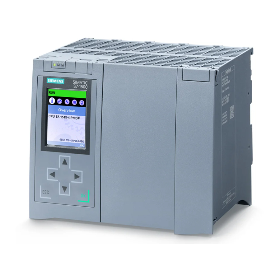
The section below gives an overview of the mode of operation of the CPU display. Detailed information on the individual options, a training course and a simulation of the selectable menu items is available in the SIMATIC S7-1500 Display Simulator (http://www.automation.siemens.com/salesmaterial-as/interactive-manuals/getting- started_simatic-s7-1500/disp_tool/start_en.html). - Page 194 CPU display Display The following figures show an example of a CPU with large display (left: for example, CPU 1516-3 PN/DP) and a CPU with small display (right: for example, CPU 1511-1 PN). ① CPU status information ② Names of the menus ③...
- Page 195 CPU display ① Regarding : CPU status information The following table shows the CPU status information that can be retrieved via the display. Table 12- 1 CPU status information C olor and icons for the Me aning sta tus data Green Orange STOP...
- Page 196 CPU display ② Regarding : Names of the m enus The following table shows the available menus of the display. Table 12- 2 Names of the menus Ma in menu items Me aning D e scription Overview The "Overview" menu contains information about the properties of the CPU and the properties of the inserted SIMATIC memory card, as well as information on whether a know-how protection or a linking of the serial number exists.
- Page 197 CPU display M enu icons The following table shows the icons that are displayed in the menus. Table 12- 3 Menu icons Ico n Me aning Editable menu item. Select the desired language here. A message is available in the next lower level page. There is an error in the next lower level page.
- Page 198 CPU display The figure below shows an exemplary view of the CPU 1516-3 PN/DP. ① Fasteners for removing and fitting the front panel Figure 12-2 Removing and fitting the front panel WA RNING P ersonal injury or material damage can occur in zone 2 hazardous areas Personal injury or material damage can occur in hazardous are zone 2 if you remove or fit the front panel while the S7-1500 automation system is running.
- Page 199 CPU display Control k eys The following keys are available on the CPU's display: ● Four arrow keys: "up", "down", "left", "right" If you press and hold an arrow key for 2 seconds, this generates an automatic scroll function. ● One ESC key ●...
- Page 200 CPU display Tooltips Some of the values shown on the display (e.g., station name, plant designation, location identifier, PROFINET device name, etc.) can exceed the available display width. This applies in particular to the CPUs with a small display. If you focus on the relevant value on the display and then press the "Left"...
- Page 201 CPU display To correctly show the aspect ratio of the uploaded image, use the following dimensions depending on the CPU images. Table 12- 4 Dimensions C PU D imensions Su pported formats CPU 1511(F)-1 PN 128 x 120 pixels Bitmap, JPEG, GIF, PNG CPU 1511C-1 PN CPU 1511T-1 PN CPU 1512C-1 PN...
- Page 202 "Multiple languages" area ("Properties > General > Multiple languages") and assign the required project languages to the interface languages. Reference Important information/special requirements for the display of F-CPUs can be found in Product Information F-CPUs S7-1500 (https://support.industry.siemens.com/cs/ww/de/view/109478599/en) Automation system System Manual, 09/2016, A5E03461182-AD...
-
Page 203: Maintenance
Maintenance 13.1 Removing and inserting I/O modules Requirement Remove or insert front connectors and I/O modules only when the voltage is switched off. NOTICE P hy sical damage can occur If you install or uninstall front connectors and/or I/O modules with switched-on voltage, this can lead to undefined conditions in your plant. -
Page 204: Replacement Of I/O Modules And Front Connectors
Maintenance 13.2 Replacement of I/O modules and front connectors 13.2 Replacement of I/O modules and front connectors 13.2.1 Coding element on the I/O module and on the front connector Function All front connectors for the I/O modules of the S7-1500 automation system/ET 200MP distributed I/O system are identical. - Page 205 Maintenance 13.2 Replacement of I/O modules and front connectors Coding element in the front c onnector When the front connector is inserted into the I/O module for the first time, one half of the coding element latches into the front connector. When you remove the front connector from the I/O module, this half of the coding element remains in the front connector, while the other half remains in the I/O module.
- Page 206 Maintenance 13.2 Replacement of I/O modules and front connectors Additional electronic coding element for fail-safe modules In as-delivered condition, a fail-safe module not only has a mechanical coding element but also an electronic rewritable memory for the PROFIsafe address. The figure below shows the electronic coding element: ①...
- Page 207 Maintenance 13.2 Replacement of I/O modules and front connectors When the front connector is inserted in the F-module, the electronic coding element engages completely in the front connector. If you remove the front connector from the F-module, the memory with the PROFIsafe address of the fail-safe module remains in the front connector. ①...
-
Page 208: Replacing An I/O Module
Maintenance 13.2 Replacement of I/O modules and front connectors 13.2.2 Replacing an I/O module Introduction ● When the front connector is first inserted into the I/O module, a part of the coding element clips onto the front connector. ● In the case of fail-safe modules, the electronic coding element with the PROFIsafe address of the F-module also engages completely in the front connector. -
Page 209: Replacing A Front Connector
Maintenance 13.2 Replacement of I/O modules and front connectors 13.2.3 Replacing a front connector Introduction ● When the front connector is first inserted into the I/O module, a part of the mechanical coding element engages on the front connector. ● In the case of fail-safe modules, the electronic coding element with the PROFIsafe address of the F-module also engages completely in the front connector. - Page 210 Maintenance 13.2 Replacement of I/O modules and front connectors 3. Additionally for F-modules: – Carefully remove the electronic coding element from the front connector. Take care not to damage the coding element. – Insert the removed electronic coding element into the new front connector. Figure 13-8 Removing the electronic coding element from the front connector and inserting it into a new front connector...
-
Page 211: Replacing The Coding Element At The Power Connector Of The System Power Supply And Load Current Supply
Maintenance 13.3 Replacing the coding element at the power connector of the system power supply and load current supply 13.3 Replacing the coding element at the power connector of the system power supply and load current supply Introduction The coding consists of a 2-part coding element. Ex factory a part of the coding element is inserted into the back side of the power connector. - Page 212 Maintenance 13.3 Replacing the coding element at the power connector of the system power supply and load current supply Procedure To replace the coding element on the power connector of the system power supply and load current supply, follow these steps: 1.
-
Page 213: Firmware Update
– For the S7-1500 automation system: Automation Technology > Automation Systems > Industrial Automation Systems SIMATIC > Controllers > SIMATIC S7 Advanced Controller SIMATIC S7 > SIMATIC S7-1500. – For the ET 200MP distributed I/O system: Automation Technology > Automation Systems >... - Page 214 When using a new firmware version, always check that the version is approved for use in the respective module. The attachments of the certificate (http://support.automation.siemens.com/WW/view/en/49368678/134200) for SIMATIC Safety specify which firmware version is approved. Options for the firmware update There are the following options for performing a firmware update: ●...
- Page 215 Maintenance 13.4 Firmware update The table below provides an overview of the media that can be used to update the firmware of a specific module. Table 13- 1 Overview of firmware update options Fi rmware update C PU C e ntral I/O mo d u l e In te rfa ce m o d u l e D i stri b u te d I/O m o d u l e STEP 7 (TIA Portal V12 or higher)
- Page 216 Maintenance 13.4 Firmware update Updat ing t he firmware The "Run firmware after update" check box is always selected. After a successful loading process the CPU includes imports the firmware and subsequently operates with the new firmware. Not e If a firmware update is interrupted, you need to remove and insert the module before starting the firmware update again.
- Page 217 (http://support.automation.siemens.com/WW/view/en/59193560) Function Manual. Procedure: online v ia the SIMATIC Automation Tool The procedure is described in the SIMATIC Automation Tool (https://support.industry.siemens.com/cs/ww/de/view/98161300) manual (included in the SIMATIC Automation Tool). Special feature at a firmware update of analog modules If you want to carry out a firmware update for analog modules, you have to supply 24 V DC load supply to the module through the power supply element.
-
Page 218: Reset To Factory Settings
13.5 Reset to factory settings Reference For additional information on the topic of firmware update, refer to the STEP 7 online help and the following FAQ on the Internet (https://support.industry.siemens.com/cs/ww/en/view/89257657). See also Overview (Page 161) 13.5 Reset to factory settings 13.5.1... - Page 219 Maintenance 13.5 Reset to factory settings Procedure using the m ode s elector Make sure that the CPU is in STOP mode (the CPU display shows STOP mode or RUN/STOP LED lights up yellow). Not e Res et to factory settings ↔ Memory reset The procedure described below also corresponds to the procedure for a memory reset: •...
- Page 220 STOP mode. The "Reset to factory settings" event is entered into the diagnostics buffer. Procedure using the SIMATIC Automation Tool The procedure is described in the SIMATIC Automation Tool (https://support.industry.siemens.com/cs/ww/de/view/98161300) manual (included in the SIMATIC Automation Tool). Automation system System Manual, 09/2016, A5E03461182-AD...
- Page 221 Additional information on "Reset to factory settings" can be found in the Function Manual Structure and use of the CPU memory (http://support.automation.siemens.com/WW/view/en/59193101) in the section on memory areas and retentivity, and in the online help for STEP 7. For information on the memory reset of the CPU, refer to the section CPU memory reset (Page 176).
-
Page 222: Resetting Interface Module (Profinet Io) To Factory Settings
Maintenance 13.5 Reset to factory settings 13.5.2 Resetting interface module (PROFINET IO) to factory settings Function The interface module can be reset to its factory state using "Reset to factory settings". M ethod of resetting an interface module to factory s ettings ●... -
Page 223: Fault Reactions With Fail-Safe Modules
Maintenance 13.6 Fault reactions with fail-safe modules Not e S ubstitute v alue behavior of the installed I/O modules during reset to factory s ettings With "Reset to factory settings", the I/O modules in the station change to the non-configured state, which means that no input data is acquired and no output data is output. - Page 224 For additional information on passivation and reintegration of F-I/O, refer to the SIMATIC Safety, Configuring and Programming (http://support.automation.siemens.com/WW/view/en/54110126) manual. Reaction of the F-module with inputs to communication errors F-modules with inputs respond differently to communication errors compared to other errors.
-
Page 225: Test Functions And Fault Resolution
Test functions and fault resolution 14.1 Test functions Introduction You have the option of testing the operation of your user program on the CPU. You can then monitor signal states and values of tags and can assign values to tags to simulate specific situations in the running of the program. - Page 226 Test functions and fault res olution 14.1 Test functions Testing with program s tatus The program status allows you to monitor the execution of the program. You can display the values of operands and the results of logic operations (RLO) allowing you to recognize and fix logical errors in your program.
- Page 227 Test functions and fault resolution 14.1 Test functions Testing with watch tables The following functions are available in the watch table: ● Monitoring of tags You can use the watch tables to monitor the current values of the individual tags of a user program or a CPU on the programming device/PC, on the display of the CPU, and on the web server.
- Page 228 Test functions and fault res olution 14.1 Test functions Testing with a force table The following functions are available in the force table: ● Monitoring of tags You can use the force tables to display the current values of the individual tags of a user program or a CPU on the programming device/PC, on the display of the CPU, and on the web server.
- Page 229 STEP 7 or via the Web server. The trace function can be called from the CPU's folder in the project tree, under the name "Traces". In connection with trace functions, also note the following FAQ on the Internet (http://www.siemens.com/automation/service&support Automation system System Manual, 09/2016, A5E03461182-AD...
-
Page 230: Reading Out/Saving Service Data
Additional information on the test functions can be found in the STEP 7 online help. Additional information about testing with trace functions is available in the Function Manual Using the trace and logic analyzer function (http://support.automation.siemens.com/WW/view/en/64897128). 14.2 Reading out/saving service data... - Page 231 IP address of the CPU is not possible. For more information on reading out service data via a user-defined page, refer to the Web server (http://support.automation.siemens.com/WW/view/en/59193560) function manual. Procedure using STEP 7 A description of how to save service data is available under the keyword "Save service data"...
- Page 232 Test functions and fault res olution 14.2 Reading out/saving service data 5. Make sure that the SIMATIC memory card is not write-protected and insert it in the slot on the CPU. (for the CPU 1517(F)-3 PN/DP, CPU 1517T(F)-3 PN/DP, CPU 1518(F)-4 PN/DP and CPU 1518(F)-4 PN/DP ODK, you need a card ≥...
-
Page 233: Technical Specifications
Technical specifications Introduction This chapter lists the technical specifications of the system: ● The standards and test values which the modules of the S7-1500 automation system/ET 200MP distributed I/O system comply with and fulfill. ● The test criteria according to which the S7-1500 automation system/ET 200MP distributed I/O system was tested. -
Page 234: Standards And Approvals
Technical specifications 15.1 Standards and Approvals 15.1 Standards and Approvals Currently valid markings and authorizations Not e Det ails on t he components of the S 7-1500 automation system/ET 200MP distributed I/ O s ystem The currently valid markings and approvals are printed on the components of the S7-1500 automation system/ET 200MP distributed I/O system. - Page 235 ● For S7-1500/ET 200MP fail-safe modules, the following also applies: 2006/42/EC "Machinery Directive" The EC declaration of conformity is held on file available to competent authorities at: Siemens AG Digital Factory Factory Automation DF FA AS DH AMB...
- Page 236 Technical specifications 15.1 Standards and Approvals c ULus HAZ. LOC. approval Underwriters Laboratories Inc. in accordance with ● UL 508 (Industrial Control Equipment) ● CSA C22.2 No. 142 (Process Control Equipment) ● ANSI/ISA 12.12.01 ● CSA C22.2 No. 213 (Hazardous Location) APPROVED for use in Class I, Division 2, Group A, B, C, D Tx;...
- Page 237 Technical specifications 15.1 Standards and Approvals IECEx approval According to IEC 60079-15 (Explosive atmospheres - Part 15: Equipment protection by type of protection "n") and IEC 60079-0 (Explosive atmospheres - Part 0: Equipment - General requirements) RCM (C-Tick) Declaration of c onformity for Australia/New Zealand The S7-1500 automation system/ET 200MP distributed I/O system fulfills the requirements of the standards: ●...
- Page 238 ● Installation of the S7-1500 automation system/ET 200MP distributed I/O system in grounded control cabinets/control boxes ● Use of noise filters in the supply lines Reference The certificates for the markings and approvals can be found on the Internet under Service&Support (http://www.siemens.com/automation/service&support). Automation system System Manual, 09/2016, A5E03461182-AD...
-
Page 239: Electromagnetic Compatibility
±1 kV (signal lines < 30 m) High-energy single pulse (surge) in accordance with IEC 61000-4-5 External protective circuit required (not for 230 V modules) (see the Defining interference-free controllers (http://support.automation.siemens.com/WW/view/en/59193566) Function Manual) ±2 kV (power supply lines) asymmetric coupling •... - Page 240 Technical specifications 15.2 Electromagnetic compatibility Sinusoidal disturbances The following table shows the electromagnetic compatibility of the S7-1500 automation system/ET 200MP distributed I/O system with regard to sinusoidal disturbances (RF radiation). Table 15- 3 Sinusoidal disturbances with RF radiation R F radiation in accordance with IEC 61000-4-3/NAMUR 21 C o rresponds with degree of se verity El ectromagnetic RF field, amplitude-modulated...
-
Page 241: Electromagnetic Compatibility Of Fail-Safe Modules
For detailed information regarding overvoltage protection, we recommend that you contact your Siemens representative or a company specializing in lightning protection. You can find more information on protection from overvoltage in the Designing interference- free controllers (http://support.automation.siemens.com/WW/view/en/59193566) function... -
Page 242: Mechanical And Climatic Ambient Conditions
Technical specifications 15.5 Mechanical and climatic ambient conditions 15.5 Mechanical and climatic ambient conditions Operating conditions The S7-1500 automation system/ET 200MP distributed I/O system is suitable for use in weather-proof, fixed locations. The operating conditions exceed requirements according to DIN IEC 60721-3-3: ●... - Page 243 Technical specifications 15.5 Mechanical and climatic ambient conditions Climatic ambient conditions The following table shows the permissible climatic ambient conditions for the S7-1500 automation system/ET 200MP distributed I/O system: Table 15- 9 Climatic ambient conditions Am bient conditions Pe rmissible range C omments Temperature: To increase the service life of the display, the display...
-
Page 244: Information On Insulation Tests, Protection Class, Degree Of Protection And Rated Voltage
Technical specifications 15.6 Information on insulation tests, protection class, degree of protection and rated voltage 15.6 Information on insulation tests, protection class, degree of protection and rated voltage Insulation The insulation is designed in accordance with the requirements of EN 61131-2: 2007. Not e Galvanic isolation with 707 V DC (Type Test) is tested for modules with 24 V DC supply voltage (SELV/PELV). -
Page 245: Use Of The S7-1500/Et 200Mp In Zone 2 Hazardous Areas
Static value: Creation as functional extra-low voltage with safe galvanic isolation according to IEC 60364-4-41. 15.7 Use of the S7-1500/ET 200MP in zone 2 hazardous areas Reference See product information Deployment of the modules in zone 2 hazardous atmospheres (http://support.automation.siemens.com/WW/view/en/19692172). Automation system System Manual, 09/2016, A5E03461182-AD... -
Page 246: Dimension Drawings
Dimension drawings Dimension drawings of the mounting rails M ounting rail 160 mm Figure A-1 Mounting rail 160 mm Automation system System Manual, 09/2016, A5E03461182-AD... - Page 247 Dimension drawings A.1 Dimension drawings of the mounting rails M ounting rail 245 mm Figure A-2 Mounting rail 245 mm M ounting rail 482.6 mm Figure A-3 Mounting rail 482.6 mm Automation system System Manual, 09/2016, A5E03461182-AD...
- Page 248 Dimension drawings A.1 Dimension drawings of the mounting rails M ounting rail 530 mm Figure A-4 Mounting rail 530 mm M ounting rail 830 mm Figure A-5 Mounting rail 830 mm Automation system System Manual, 09/2016, A5E03461182-AD...
-
Page 249: Dimension Drawing Of Shielding Bracket For 35 Mm Modules
Dimension drawings A.2 Dimension drawing of shielding bracket for 35 mm modules M ounting rail 2000 mm Figure A-6 Mounting rail 2000 mm Dimension drawing of shielding bracket for 35 mm modules Figure A-7 Dimension drawing of shielding bracket for 35 mm modules Automation system System Manual, 09/2016, A5E03461182-AD... -
Page 250: Dimension Drawing Of Shielding Bracket For 25 Mm Modules
Dimension drawings A.3 Dimension drawing of shielding bracket for 25 mm modules Dimension drawing of shielding bracket for 25 mm modules Figure A-8 Dimension drawing of shielding bracket for 25 mm modules Dimension drawing of shielding bracket for 35 mm modules Figure A-9 Dimension drawing of shielding bracket for 35 mm modules Automation system... -
Page 251: Dimension Drawing Of Shielding Bracket For 25 Mm Modules
Dimension drawings A.5 Dimension drawing of shielding bracket for 25 mm modules Dimension drawing of shielding bracket for 25 mm modules Figure A-10 Dimension drawing of shielding bracket for 25 mm modules Dimension drawing of shielding bracket for 35 mm modules Figure A-11 Dimension drawing of shielding bracket for 35 mm modules Dimension drawing of shielding bracket for 25 mm modules... -
Page 252: Dimension Drawings Of The Labeling Strips
Dimension drawings A.8 Dimension drawings of the labeling strips Dimension drawings of the labeling strips Figure A-13 Dimension drawing of labeling strips for 35 mm modules Figure A-14 Dimension drawing of labeling strips for 25 mm modules Dimension drawing of test probe for measurement tap To perform measurements on the front connector of the S7-1500/ET 200MP automation system, you need a test probe with the following properties: ●... -
Page 253: Accessories/Spare Parts
Accessories/spare parts Accessories for the S7-1500 automation system/ET 200MP distributed I/O system Table B- 1 General accessories D e signation Article number Mounting rail 6ES7590-1AB60-0AA0 Mounting rail, 160 mm (with drill holes) • 6ES7590-1AC40-0AA0 Mounting rail, 245 mm (with drill holes) •... - Page 254 Accessories/spare parts D e signation Article number Power cable connector with coding element for power supplies 6ES7590-8AA00-0AA0 (spare part), 10 units Potential bridge for front connector (spare part), 20 units 6ES7592-3AA00-0AA0 Universal front cover for 35 mm I/O modules (spare part), 5 units 6ES7528-0AA00-7AA0 Consists of: 5 x front cover •...
- Page 255 Accessories/spare parts Online catalog Other article numbers for the S7-1500 automation system/ET 200MP distributed I/O system can be found on the Internet (https://mall.industry.siemens.com) in the online catalog and the online order system. Accessories for fail-safe modules S7-1500/ET 200MP Table B- 2...
-
Page 256: Glossary
Glossary Automation system Programmable logic controller for the closed-loop and open-loop control of process chains in the process engineering industry and manufacturing technology. The automation system consists of different components and integrated system functions according to the automation task. Baud rate Data transmission rate indicates the number of bits transmitted per second (baud rate = bit rate). - Page 257 Glossary Connection plug Physical connection between device and cable. Consistent data Data whose content belongs together and must not be separated is known as consistent data. Counter Counters are components of the system memory of the CPU. You can modify the content of the "counter cells"...
- Page 258 Glossary Device names Before an IO device can be addressed by an IO controller, it must have a device name. This approach was chosen for PROFINET because names are easier to administer than complex IP addresses. In its delivery state, an IO device has no device name. An IO device can only be addressed by an IO controller - e.g., for transferring configuration data (including the IP address) during startup, or for user data exchange during cyclic operation - after it has been assigned a device name with the programming device/PC.
- Page 259 Glossary Function A function (FC) is a code block with no static data. A function allows you to pass parameters in the user program. Functions are thus suited for programming frequently recurring complex functions, such as calculations. Function block A function block (FB) is a code block with static data. An FB allows you to pass parameters in the user program.
- Page 260 Glossary Identification data Information that is saved in modules, and that supports the user in reviewing the system configuration and locating hardware changes. Instance data block Each call of a function block in the STEP 7 user program is assigned a data block, which is automatically generated.
- Page 261 Glossary Interrupt, update When it receives an update interrupt, the operating system calls the update interrupt OB. This may happen if you changed a parameter on a slot of a device. IP address The IP address is made up of four decimal numbers with a range of values from 0 through 255.
- Page 262 Glossary Organization block Organization blocks (OBs) form the interface between the operating system of the CPU and the user program. The organization blocks determine the order in which the user program is executed. Parameter ● Tag of a STEP 7 code block: ●...
- Page 263 Glossary PROFIBUS PROcess FIeld BUS, process and fieldbus standard that is specified in IEC 61158 Type 3. It specifies functional, electrical and mechanical characteristics for a bit-serial field bus system. PROFIBUS supports the protocols DP (= Distributed I/O), FMS (= Fieldbus Message Specification), PA (= Process Automation), or TF (= Technological Functions).
- Page 264 Glossary All the modules attached to a mounting rail. Runtime error Error that occurs during execution of the user program in the automation system (thus not in the process). SELV S afety E xtra Low V oltage = Safety extra-low voltage Slave station A slave may only exchange data with a master after being requested to by the master.
- Page 265 Glossary System power supply Consists of the integrated system power supply of the CPU/interface module and additional power supplies (PS), if necessary. The system power supply serves exclusively to supply the I/O modules via the backplane bus. Technology object A technology object supports you in the configuration and commissioning of a technological function.
-
Page 266: Index
Index Procedure, 164 Removing/inserting SIMATIC memory card, 165 Reset to factory settings, 222 Components 24 V DC supply, 64 Overview of the ET 200MP, 29 Configuration, 69 Basics, 101 Electrical, 72 Accessible devices ET 200MP, 23 Firmware update, 216 On grounded reference potential, 69 Accessories, 253 Configuration control, 142, 143 Addressing, 106... - Page 267 Index Electromagnetic compatibility (EMC), 239 Hardware configuration ET 200MP DP Electrostatic discharge, 239 Slots, 37 EMC (Electromagnetic compatibility), 239 Hardware configuration ET 200MP PN Disturbances, 239 Slots, 36 Radio interference, 240 EMERGENCY-STOP devices, 63 ET 200MP, 22 Accessories, 253 I/O module, 30 Components, 29 Front connectors, 85 Configuration example, 27...
- Page 268 Index STARTUP, 171 STOP, 173 Main entry, 22 Option handling, (See configuration control) Maintenance Overall configuration, 71 Coding element, 204 Overload, 46 Firmware update, 213 Overload behavior, 120 Reading out service data, 230 Overview Removal and insertion, 203 Components of an S7-1500, 29 Replace module, 208 Grounding the CPU, 71 Replacing a front connector, 209...
- Page 269 Index S7-1500 U connector, 30 Configuration, 20 Uninstalling Configuration example, 21 CPU, 59 Field of application, 20 I/O module, 62 Overview of components, 29 Load current supply, 57 S7-1500 CPU/ET 200MP interface module System power supply, 55 Rules and regulations for operation, 63 S7-1500 hardware configuration Slots, 34 Safe galvanic isolation, 69...