Chapters
Table of Contents

Related Manuals for LG R410A


Summary of Contents for LG R410A
-
Page 1: Air Conditioner
System Air Conditioner SERVICE MANUAL R410A MODELS: ARUN/ARUV Series ARNU Series CAUTION • BEFORE SERVICING THE UNIT, READ THE SAFETY PRECAUTIONS IN THIS MANUAL. • ONLY FOR AUTHORIZED SERVICE PERSONNEL. -
Page 2: Table Of Contents
Air Conditioner Service Manual TABLE OF CONTENTS Safety Precautions ..................3 Model Names ....................11 External Appearance ..................12 Nomenclature ....................14 Outdoor Units Information .................15 Indoor Units ...................17 Ceiling Mounted Cassette Type (4 way)............19 Art Cool Type ....................31 Art Cool Type(Wide)..................45 Ceiling Concealed Duct Type (Low static) ..........58 Ceiling Concealed Duct Type (High static)..........68 Outdoor Units ..................79... -
Page 3: Safety Precautions
Safety Precautions Safety Precautions To prevent injury to the user or other people and property damage, the following instructions must be followed. I Incorrect operation due to ignoring instruction will cause harm or damage. The seriousness is classified by the following indications. WARNING This symbol indicates the possibility of death or serious injury. - Page 4 Safety Precautions For re-installation of the installed product, always Do not install, remove, or re-install the unit by contact a dealer or an Authorized Service Center. yourself (customer). • There is risk of fire, electric shock, explosion, or injury. • There is risk of fire, electric shock, explosion, or injury. Do not store or use flammable gas or Use the correctly rated breaker or fuse.
- Page 5 Safety Precautions Ventilate before operating air conditioner when gas Securely install the cover of control box and the goes out. panel. • It may cause explosion, fire, and burn. • If the cover and panel are installed securely, dust or water may enter the outdoor unit and fire or electric shock may result.
- Page 6 Safety Precautions When the product is soaked (flooded or Be cautious not to touch the sharp edges when submerged), contact an Authorized Service Center. installing. • There is risk of fire or electric shock. • It may cause injury. Take care to ensure that nobody could step on or Do not open the inlet grill of the product during fall onto the outdoor unit.
- Page 7 Safety Precautions Use power cables of sufficient current Do not use the product for special purposes, such carrying capacity and rating. as preserving foods, works of art, etc. It is a con- sumer air conditioner, not a precision refrigeration system. •...
- Page 8 Safety Precautions I Operation Do not use the air conditioner in special Do not block the inlet or outlet. environments. • Oil, steam, sulfuric smoke, etc. can significantly reduce • It may cause failure of appliance or accident. the performance of the air conditioner or damage its parts.
- Page 9 Safety Precautions Safely dispose of the packing materials. Turn on the power at least 2 hours before starting operation.(In case of outdoor temperature 5°C below) • Packing materials, such as mails and other metal or • Starting operation immediately after turning on the wooden parts, may cause stabs or other injuries.
- Page 10 Part 1 General Information 1. Model Names ..............11 1.1 Indoor Unit .............11 1.2 Outdoor Unit ............11 2. External Appearance.............12 2.1 Indoor Unit .............12 2.2 Outdoor Unit ............13 3. Nomenclature..............14 3.1 Indoor Unit .............14 3.2 Outdoor Unit ............14 4. Outdoor Units information..........15...
-
Page 11: Model Names
Model Names 1. Model Names 1.1 Indoor Unit Capacity(Btu/h(kW)) Category Chassis Name (2.2) (2.8) (3.6) (5.6) (7.1) (8.2) (10.6) (12.3) (14.1) Wall Mounted ARNU07GSE*0 ARNU09GSE*0 ARNU12GSE*0 (General) ARNU18GS5*0 ARNU24GS5*0 Mirror ARNU07GSE*0 ARNU09GSE*0 ARNU12GSE*0 ARNU18GS3*0 ARNU24GS3*0 ART COOL ART COOL ARNU07GSP*0 ARNU09GSP*0 ARNU12GSP*0 ART COOL Wi d e... -
Page 12: External Appearance
External Appearance 2. External Appearance 2.1 Indoor Units Ceiling Cassette- 1Way Ceiling Cassette -2Way ARNU07GTJ*0 ARNU18GTL*0 ARNU09GTJ*0 ARNU24GTL*0 ARNU12GTJ*0 * A:Basic, C:Plasma * A:Basic, C:Plasma Ceiling Cassette- 4Way Ceiling Concealed Duct - High Static ARNU09GTE*0 ARNU18GBHA0 ARNU12GTE*0 ARNU24GBHA0 ARNU18GTE*0 ARNU28GBGA0 ARNU24GTH*0 ARNU36GBGA0 ARNU28GTH*0... -
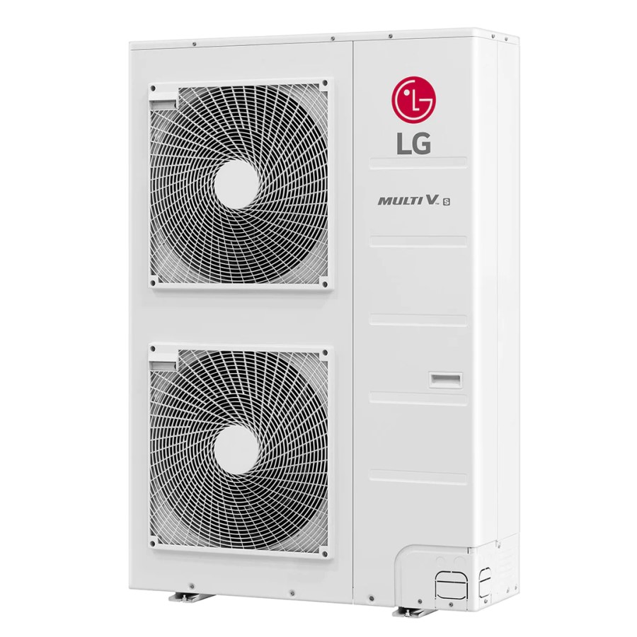
Page 13: Outdoor Unit
External Appearance 2.2 Outdoor Units ARUN1008F20 10HP Service Manual 13... -
Page 14: Nomenclature
N: AC Inverter and H/P V: AC Inverter and C/O U: DC Inverter and H/P and C/O Indicates that this is System Indoor Unit using the R410A 3.2 Outdoor Unit Serial Number Chasiss Type V : UV Chassis 1 : UV1 Chassis... -
Page 15: Outdoor Units Information
Outdoor units Information 4. Outdoor Units Information CAUTION: A ratio of the connectable Indoor Units with the Outdoor: Within 50 ~ 130% A ratio of the running Indoor Units with the Outdoor: Within 10 ~ 100% 130% combination ratio cause a reduction of capacity. Power Supply: Outdoor Unit (3Ø, 380 ~ 415V, 50Hz) I Heat Pump System(HP) -
Page 17: Indoor Units
Indoor Units Service Manual 17... - Page 18 Indoor Unit...
-
Page 19: Ceiling Mounted Cassette Type (4Way)
Ceiling Mounted Cassette Type (4Way) 1. Specifications ................20 2. Functions ..................23 3. Operation Details................24 4. Dimensions .................26 5. Piping Diagrams .................28 6. Wiring Diagrams .................29 Service Manual 19... -
Page 20: Specifications
Specification 1. Specification Type 4 Way Ceiling Cassette ARNU09GTEA0 ARNU12GTEA0 ARNU18GTEA0 Model Unit 2,800 3,600 5,600 Cooling Capacity kcal/h 2,400 3,100 4,800 Btu/h 9,600 12,300 19,100 3,200 4,000 6,300 2,800 3,400 5,400 Heating Capacity kcal/h Btu/h 10,900 13,600 21,500 Galvanized Steel Plate Galvanized Steel Plate Galvanized Steel Plate Casing... - Page 21 Specification Type 4 Way Ceiling Cassette Model Unit ARNU24GTHA0 ARNU28GTHA0 ARNU36GTDA0 7,100 8,200 10,600 6,100 7,100 9,100 Cooling Capacity kcal/h Btu/h 24,200 28,000 36,200 8,000 9,200 11,900 Heating Capacity kcal/h 6,900 8,000 10,200 Btu/h 27,300 31,500 40,600 Galvanized Steel Plate Galvanized Steel Plate Galvanized Steel Plate Casing...
- Page 22 Specification Type 4 Way Ceiling Cassette Model Unit ARNU42GTDA0 ARNU48GTDA0 12,300 14,100 Cooling Capacity kcal/h 10,600 12,100 42,000 48,100 Btu/h 13,800 15,900 Heating Capacity kcal/h 11,000 13,200 Btu/h 43,800 51,200 Casing Galvanized Steel Plate Galvanized Steel Plate 840x840x288 840x840x288 Body inch 33.0x33.0x11.3 33.0x33.0x11.3...
-
Page 23: Functions
Functions 2. Functions Indoor Unit Operation ON/OFF by Remote controller Sensing the Room Temperature • Room temperature sensor. (Thermistor) Room temperature control • Maintains the room temperature in accordance with the Setting Temperature. • Indoor fan is delayed for 5 seconds at the starting. Starting Current Control •... -
Page 24: Operation Detail
Operation Detail 3. Operation Detail (1) The function of main control I Time Delay Safety Control • 5 sec ... Vertical air flow direction control louvers open in 5 seconds to prevent noise between louvers and wind. • 5 sec ... The 4-way valve is ceased for 5 sec. to prevent the refrigerant-gas abnormal noise when the Heating operation is OFF or switched to the other operation mode when compress is off. - Page 25 Operation Detail I Heating Mode Operation The unit will operate according to the setting by the remote controller and the operation diagram is shown as following. Intake Air temperature minimum 3min Setting Temperature .+3°C (Compressor OFF) Setting Temperature (Compressor ON) minimum minimum minimum...
-
Page 26: Dimensions
Dimensions 4. Dimensions ARNU09GTEA0 ARNU12GTEA0 600 (Ceiling opening) ARNU18GTEA0 39.5 521(Hanging bolt) 39.5 570 Unit size Unit:mm (unit : mm) Number Name Descripition Liquid pipe connection Unit size(9k, 12k, 18k):Ø6.35 Gas pipe connection Unit size(9k, 12k, 18k):Ø12.7 Drain pipe connection Power supply connection Air discharge grill Air suction grill... - Page 27 Dimensions ARNU24GTHA0 ARNU28GTHA0 ARNU36GTDA0 ARNU38GTDA0 ARNU42GTDA0 ARNU48GTDA0 875 (Ceiling opening) 785(Hanging bolt) 840 Unit size Unit:mm (unit : mm) Number Name Descripition Liquid pipe connection Unit Size (24k, 28k, 36k, 42k, 48k):Ø9.52 Gas pipe connection Unit Size(24k, 28k, 36k, 42k, 48k):Ø15.88 Drain pipe connection Power supply connection Air discharge grill...
-
Page 28: Piping Diagrams
Piping Diagrams 5. Piping Diagrams :Cooling Heat Exchanger :Heating Filter Turbo Fan Filter lndoor unit : Thermistor Refrigerant pipe connection port diameter [unit: mm(inch)] Model Liquid ARNU09GTEA0 Ø12.7(1/2) Ø6.35(1/4) ARNU12GTEA0 Ø12.7(1/2) Ø6.35(1/4) ARNU18GTEA0 Ø12.7(1/2) Ø6.35(1/4) ARNU24GTHA0 Ø15.88(5/8) Ø9.52(3/8) ARNU28GTHA0 Ø15.88(5/8) Ø9.52(3/8) ARNU36GTDA0 Ø15.88(5/8) -
Page 29: Wiring Diagrams
Wiring Diagrams 6. Wiring Diagrams TE/TH CONNECTOR NUMBER SPEC DESCRIPTION CN-POWER AC POWER SUPPLY AC POWER LINE INPUT FOR INDOOR CONTROLLER CN-MOTOR2 FAN MOTOR OUTPUT MOTOR OUTPUT OF BLDC CN-D/PUMP DRAIN PUMP OUTPUT AC OUTPUT FOR DRAIN PUMP CN-COMM COMMUNICATION CONNECTION BETWEEN INDOOR AND OUTDOOR CN-DISP1 DISPLAY... - Page 30 Indoor Unit...
-
Page 31: Art Cool Type
Art Cool Type 1. Specification ................32 2. Functions ..................33 3. Operation Details................34 4. Dimensions .................41 5. Piping Diagrams .................42 6. Wiring Diagrams .................43 Service Manual 31... -
Page 32: Specification
Specification 1. Specification Type ARTCOOL Model Unit ARNU07GSP*0 ARNU09GSP*0 ARNU12GSP*0 2,200 2,800 3,600 1,900 2,400 3,100 Cooling Capacity kcal/h Btu/h 7,500 9,600 12,300 2,500 3,200 4,000 Heating Capacity kcal/h 2,200 2,800 3,400 Btu/h 8,500 10,900 13,600 570x137x568 570x137x568 570x137x568 Dimensions (W*D*H) Body inch 22.4x5.4x22.3 22.4x5.4x22.3... -
Page 33: Functions
Functions 2. Functions Indoor Unit Operation ON/OFF by Remote controller Sensing the Room Temperature • Room temperature sensor. (THERMISTOR) Room temperature control • Maintains the room temperature in accordance with the Setting temperature Starting Current Control • Indoor fan is delayed for 5 sec at the starting. Time Delay Safety Control •... -
Page 34: Operation Details
Operation Details 3. Operation Details Function of Controls DISPLAY (1) High quality LCD remote controller supplied Operation Indicator • On while in appliance operation, off while in appliance pause Timer(on/off) and Sleep timer Indicator • On while in timer mode (on/off) and in sleep timer mode, off when timer mode is completed or canceled Defrost Indicator •... - Page 35 Operation Details I Healthy Dehumidification Mode • When the dehumidification operation input by the remote controller is received, the intake air temperature is detected and the setting temp is automatically set according to the intake air temperature. 26°C ≤ Intake Air Temp =>...
- Page 36 Operation Details 26°C ≤ Intake Air Temp => 25°C 24°C ≤ Intake Air Temp<26°C => Intake Air Temp+1°C 22°C ≤ Intake Air Temp<24°C => Intake Air Temp+0.5°C 18°C ≤ Intake Air Temp<22°C => Intake Air Temp Intake Air Temp<18°C => 18°C •...
- Page 37 Operation Details • At the beginning of Fuzzy mode operation, the setting temperature is automatically selected according to the intake air temp at that time. 26°C ≤ Intake Air Temp => 25°C 24°C ≤ Intake Air Temp<26°C => Intake Air Temp+1°C 22°C ≤...
- Page 38 Operation Details I Off-Timer <=> On-Timer Operation • When the set time is reached after the on/off time is input by the remote controller, the on/off-timer operation is carried out according to the set time. I Sleep Timer Operation • When the sleep time is reached after <1,2,3,4,5,6,7,0(cancel) hr> is input by the remote controller while in appliance operation, the operation of the appliance stops.
-
Page 39: Forced Operation
- Operation Mode/Setting Temp/Selected Airflow Speed - Sleep Timer Mode/Remaining Time of Sleep Timer (unit of hour) I Forced Operation • Operation procedures when the remote control can't be used. • The operation will be started if the power button is pressed. •... - Page 40 I Air Cleaner Operation • When an air cleaner function is selected during Air Conditioner operation - Plasma air cleaner function will be operated while in any operation mode with selecting the function. - The function is to be stopped while it is operating with selecting the function. •...
-
Page 41: Dimensions
Dimensions 4. Dimensions ARNU07GSP*0 ARNU09GSP*0 ARNU12GSP*0 Hanger Hole Fix Hole Pipe Hole (Unit: mm) Note: 1. Pipe Specification(mm) More than 10cm Model Liquid 9, 12k Ø 6.35 Ø 9.52 More than 50cm More than 50cm More than 2m Model ARNU07GSP*0 ARNU09GSP*0 ARNU12GSP*0 Service Manual 41... -
Page 42: Piping Diagrams
Piping Diagrams 5. Piping Diagrams :Cooling Heat Exchanger :Heating Filter Turbo Fan Filter lndoor unit : Thermistor Refrigerant pipe connection port diameter [unit: mm(inch)] Model Liquid ARNU07GSP*0 12.7(1/2) 6.35(1/4) ARNU09GSP*0 ARNU12GSP*0 *(Color): M(Metal), D(Wood), B(Blue), W(White) Indoor Unit... - Page 43 Wirinjg Diagrams 6. Wiring Diagrams BLDC MOTOR CONNECTOR NUMBER SPEC DESCRIPTION CN-POWER AC POWER SUPPLY AC POWER LINE INPUT FOR INDOOR CONTROLLER CN-MOTOR2 FAN MOTOR OUTPUT MOTOR OUTPUT OF BLDC CN-COM COMMUNICATION COMMUNICATION BETWEEN INDOOR AND OUTDOOR CN-LEV LEV OUTPUT LEV CONTROL OUTPUT CN-D1 DISPLAY...
- Page 44 Indoor Unit...
-
Page 45: Art Cool Type(Wide)
Art Cool Type(Wide) 1. Specification ................46 2. Installation...................47 3. Operation Details................48 4. Dimensions .................55 5. Piping Diagrams .................56 6. Wiring Diagrams .................57 Service Manual 45... -
Page 46: Specification
Specification 1. Specification Type ARTCOOL Wide Model Unit ARNU18GSV*0 5,600 Cooling Capacity kcal/h 4,800 19,100 Btu/h 6,300 Heating Capacity kcal/h 5,400 Btu/h 21,500 928x147x522 Dimensions (W*D*H) Body 36.5x5.8x20.6 inch Rows x Columns x FPI 2x16x20 Coil Face Area 0.24 Type Turbo Fan Motor Output x Number Running Current... - Page 47 Functions 2. Functions Indoor Unit Operation ON/OFF by Remote controller Sensing the Room Temperature • Room temperature sensor. (THERMISTOR) Room temperature control • Maintains the room temperature in accordance with the Setting Temp. Starting Current Control • Indoor fan is delayed for 5 sec at the starting. Time Delay Safety Control •...
-
Page 48: Operation Details
Operation Details 3. Operation Details Function of Controls DISPLAY 1) High quality LCD remote controller supplied Operation Indicator • On while in appliance operation, off while in appliance pause Timer Indicator • On while in timer mode (on/off) and in sleep timer mode, off when timer mode is completed or canceled Defrost Indicator •... - Page 49 Operation Details I Healthy Dehumidification Mode • When the dehumidification operation input by the remote controller is received, the intake air temperature is detected and the setting temp is automatically set according to the intake air temperature. 26°C ≤ Intake Air Temp =>...
- Page 50 Operation Details 26°C ≤ Intake Air Temp => 25°C 24°C ≤ Intake Air Temp<26°C => Intake Air Temp+1°C 22°C ≤ Intake Air Temp<24°C => Intake Air Temp+0.5°C 18°C ≤ Intake Air Temp<22°C => Intake Air Temp Intake Air Temp<18°C => 18°C •...
- Page 51 Operation Details • At the beginning of Fuzzy mode operation, the setting temperature is automatically selected according to the intake air temp at that time. 26°C ≤ Intake Air Temp => 25°C 24°C ≤ Intake Air Temp<26°C => Intake Air Temp+1°C 22°C ≤...
- Page 52 Operation Details I Off-Timer <=> On-Timer Operation • When the set time is reached after the on/off time is input by the remote controller, the on/off-timer operation is carried out according to the set time. I Sleep Timer Operation • When the sleep time is reached after <1,2,3,4,5,6,7,0(cancel) hr> is input by the remote controller while in appliance operation, the operation of the appliance stops.
-
Page 53: Test Operation Control
Operation Details - State of Operation ON/OFF - Operation Mode/Setting Temp/Selected Airflow Speed - Sleep Timer Mode/Remaining Time of Sleep Timer (unit of hour) I Forced Operation (Outdoor unit C/O Model) • To operate the appliance by force in case that the remote controller is lost, the forced operation button is on the main unit of the appliance to operate the appliance in the standard conditions. - Page 54 Operation Details I Buzzer Sounding Operation • When the appliance-operation key is input by the remote controller, the short “beep-beep-” sounds. • When the appliance-pause key is input by the remote controller, the long “beep—” sounds. I Air Cleaner Operation •...
-
Page 55: Dimensions
Dimensions 4. Dimensions ARNU18GSV*0 Pipe Hole Pipe Hole More than 10cm More than More than 50cm 50cm More than 2m 60mm 60mm (Unit: mm) Model ARNU18GSV*0 Service Manual 55... -
Page 56: Piping Diagrams
Piping Diagrams 5. Piping Diagrams :Cooling Heat Exchanger :Heating Filter Turbo Fan Filter lndoor unit : Thermistor Refrigerant pipe connection port diameter [unit: mm(inch)] Model Liquid ARNU18GSV*0 Ø12.7(1/2) Ø6.35(1/4) *(Color): M(Metal), D(Wood), B(Blue), W(White) Indoor Unit... -
Page 57: Wiring Diagrams
Wiring Diagrams 6. Wiring Diagrams BLDC MOTOR BLDC MOTOR CN-D2(15P) CN-D1(4P) FORCE SAFETY DISPLAY ASM CONNECTOR NUMBER SPEC DESCRIPTION CN-POWER AC POWER SUPPLY AC POWER LINE INPUT FOR INDOOR CONTROLLER CN-MOTOR2 FAN MOTOR OUTPUT MOTOR OUTPUT OF BLDC CN-COM COMMUNICATION COMMUNICATION BETWEEN INDOOR AND OUTDOOR CN-LEV LEV OUTPUT... -
Page 58: Ceiling Concealed Duct Type (Low Static)
Ceiling Concealed Duct Type (Low static) 1. Specifications ................59 2. Funtion ..................61 3. Operation Details................62 4. Dimensions .................65 5. Piping Diagrams .................66 6. Wiring Diagrams .................67 Indoor Unit... -
Page 59: Specifications
Specification 1. Specification Type Ceiling Concealed Duct (Low Static)(Preliminary) Model Unit ARNU07GB1G0 ARNU09GB1G0 ARNU12GB1G0 2,200 2,800 3,600 Cooling Capacity kcal/h 1,900 2,400 3,100 7,500 9,600 12,300 Btu/h 2,500 3,200 4,000 Heating Capacity kcal/h 2,200 2,800 3,400 Btu/h 8,500 10,900 13,600 Casing Galvanized Steel Plate Galvanized Steel Plate... - Page 60 Specification Type Ceiling Concealed Duct (Low Static)(Preliminary) ARNU18GB2G0 ARNU24GB2G0 Model Unit 5,600 7,000 Cooling Capacity kcal/h 4,800 6,100 Btu/h 19,100 24,200 6,300 8,000 5,400 6,900 Heating Capacity kcal/h Btu/h 21,500 27,300 Casing Galvanized Steel Plate Galvanized Steel Plate 1100 x 575 x 190 1100 x 575 x 190 Dimensions (W*D*H) Body inch...
-
Page 61: Funtion
Functions 2. Funtion Indoor Unit Operation ON/OFF by Remote controller Sensing the Room Temperature • Room temperature sensor. (Thermistor) Room temperature control • Maintains the room temperature in accordance with the Setting Temperature. • Indoor fan is delayed for 5 seconds at the starting. Starting Current Control •... -
Page 62: Operation Details
Operation Details 3. Operation Details (1) The function of main control I Time Delay safety Control • 30sec ... The 4-way valve is ceased for 30sec. to prevent the refrigerant-gas abnormal noise when the Heating opera- tion is OFF or switched to the other operation mode while compress is off. While compressor is running, it takes 3~5 seconds to switch to another mode. - Page 63 Operation Details I Heating Mode Operation The unit will operate according to the setting by the remote controller and the operation diagram is shown as following. Indoor unit 40°C Heat-Exchanger temperature 33°C 30°C 27°C 20°C Intake Air Temperature 3min Low fan during 10sec Setting Temperature +3°C (Compressor OFF)
- Page 64 Operation Details I Hot-Start Control • The indoor fan does not rotate until the indoor unit Hex-Exchanger temperature reaches 30°C. • The operation diagram is as following. Indoor unit Heat-Exchanger temperature 30°C Hotstart 1min 1min Compressor Outdoor fan Setting fan Setting fan Indoor fan spped...
-
Page 65: Dimensions
Dimensional Drawings 4. Dimensional Drawings ARNU07GB1G(A)0 / ARNU09GB1G(A)0 / ARNU12GB1G(A)0 ARNU18GB2G(A)0 / ARNU24GB2G(A)0 Drainage hole Dimension Capacity 7/9/12k BTU/h 93.5 20.6 18/24k BTU/h 1130 1180 93.5 20.6 1065 (unit: mm) Front view Top view (unit: mm) H=20 or more ❉ Suitable dimension "H" is necessary to get a slope to drain as figure Front Service Manual 65... -
Page 66: Piping Diagrams
Piping Diagrams 5. Piping Diagrams :Cooling Heat Exchanger :Heating Filter Sirocco Fan Filter lndoor unit : Thermistor Refrigerant pipe connection port diameter [unit: mm(inch)] MODEL LIQUID ARNU07GB1G(A)0 / ARNU09GB1G(A)0 Ø12.7(1/2) Ø6.35(1/4) ARNU12GB1G(A)0 / ARNU18GB2G(A)0 / ARNU24GB2G(A)0 Ø15.88(5/8) Ø9.52(3/8) Indoor Unit... -
Page 67: Wiring Diagrams
Wiring Diagrams 6. Wiring Diagrams CONNECTOR SPEC. COLOR DESCRIPTION NUMBER CN-MOTOR1 AC FAN MOTOR OUTPUT WHITE MOTOR OUTPUT OF PHASE CONTROL CN-MOTOR2 AC FAN MOTOR OUTPUT WHITE MOTOR OUTPUT OF PHASE CONTROL CN-PIPE/O DISCHARGE PIPE THERMISTOR DISCHARGE PIPE THERMISTOR CN-PIPE PIPE SENSOR WHITE PIPE THERMISTOR... -
Page 68: Ceiling Concealed Duct Type (High Static)
Ceiling Concealed Duct Type (High Static) 1. Specifications ................69 2. Funtion ..................71 3. Operation Details................72 4. Dimensions .................75 5. Piping Diagrams .................76 6. Wiring Diagrams .................77 Indoor Unit... - Page 69 Specifications 1. Specification Ceiling Concealed Duct(High Static)(Preliminary) Type Model Unit ARNU18GBHA0 ARNU24GBHA0 ARNU28GBGA0 5,600 7,100 8,200 Cooling Capacity kcal/h 4,800 6,100 7,100 Btu/h 19,100 24,200 28,000 6,300 8,000 9,200 Heating Capacity kcal/h 5,400 6,900 8,000 Btu/h 21,500 27,300 31,500 Casing Galvanized Steel Plate Galvanized Steel Plate Galvanized Steel Plate...
- Page 70 Specifications Type Ceiling Concealed Duct(High Static)(Preliminary) Model Unit ARNU36GBGA0 ARNU42GBGA0 ARNU48GBRA0 10,600 12,300 14,100 Cooling Capacity kcal/h 9,100 10,600 12,100 36,200 42,000 48,100 Btu/h 11,900 13,800 15,900 Heating Capacity kcal/h 10,200 11,000 13,200 Btu/h 40,600 43,800 51,200 Casing Galvanized Steel Plate Galvanized Steel Plate Galvanized Steel Plate 1182x450x298...
-
Page 71: Funtion
Funtion 2. Funtion Indoor Unit Operation ON/OFF by Remote controller Sensing the Room Temperature • Room temperature sensor. (Thermistor) • Maintains the room temperature in accordance with the Setting Temperature. Room temperature control • Indoor fan is delayed for 5 seconds at the starting. Starting Current Control •... -
Page 72: Operation Details
Operation Details 3. Operation Details (1) The function of main control I Time Delay safety Control • 30sec ... The 4-way valve is ceased for 30sec. to prevent the refrigerant-gas abnormal noise when the Heating opera- tion is OFF or switched to the other operation mode while compress is off. While compressor is running, it takes 3~5 seconds to switch to another mode. - Page 73 Operation Details I Heating Mode Operation The unit will operate according to the setting by the remote controller and the operation diagram is shown as following. Indoor unit 40°C Heat-Exchanger temperature 33°C 30°C 27°C 20°C Intake Air Temperature 3min Low fan during 10sec Setting Temperature +3°C (Compressor OFF)
- Page 74 Operation Details I Hot-Start Control • The indoor fan does not rotate until the indoor unit Hex-Exchanger temperature reaches 30°C. • The operation diagram is as following. Indoor unit Heat-Exchanger temperature 30°C Hotstart 1min 1min Compressor Outdoor fan Setting fan Setting fan Indoor fan spped...
-
Page 75: Dimensions
Dimensions 4. Dimensional Drawings ARNU18GBHA0 ARNU42GBGA0 ARNU24GBHA0 ARNU48GBRA0 ARNU28GBGA0 ARNU36GBGA0 (Unit: mm) Model 18/24k BH 932 882 158 260 243 212 243 106 130 19 165 28/36/42k BG 1232 1182 186 298 232 243 232 243 116 160 19 165 48k BR 1282 1230 120 1006 294 380... -
Page 76: Piping Diagrams
Piping Diagrams 5. Piping Diagrams :Cooling Heat Exchanger :Heating Filter Sirocco Fan Filter lndoor unit : Thermistor Refrigerant pipe connection port diameter [unit: mm(inch)] MODEL LIQUID ARNU18GBHA0 Ø12.7(1/2) Ø6.35(1/4) ARNU24GBHA0 Ø15.88(5/8) Ø9.52(3/8) ARNU28GBGA0 Ø15.88(5/8) Ø9.52(3/8) ARNU36GBGA0 Ø15.88(5/8) Ø9.52(3/8) ARNU42GBGA0 Ø15.88(5/8) Ø9.52(3/8) ARNU48GBRA0 Ø15.88(5/8) -
Page 77: Wiring Diagrams
Wiring Diagrams 6. Wiring Diagrams BH Chassis CONNECTOR NUMBER LOCATION POINT FUNCTION CN-POWER AC POWER SUPPLY AC POWER LINE INPUT FOR INDOOR CONTROLLER CN-MOTOR2 FAN MOTOR OUTPUT MOTOR OUTPUT OF BLDC CN-D/PUMP DRAIN PUMP OUTPUT AC OUTPUT FOR DRAIN PUMP CN-COMM COMMUNICATION CONNECTION BETWEEN INDOOR AND OUTDOOR... - Page 78 Wiring Diagrams BG/BR Chassis CONNECTOR NUMBER LOCATION POINT FUNCTION CN-POWER AC POWER SUPPLY AC POWER LINE INPUT FOR INDOOR CONTROLLER CN-MOTOR2 FAN MOTOR OUTPUT MOTOR OUTPUT OF BLDC CN-D/PUMP DRAIN PUMP OUTPUT AC OUTPUT FOR DRAIN PUMP CN-COMM COMMUNICATION CONNECTION BETWEEN INDOOR AND OUTDOOR CN-LEV LEV OUTPUT LEV CONTROL OUTPUT...
-
Page 79: Outdoor Units
Outdoor unit Service Manual 79... - Page 80 ARUN Series 1. Specifications ................81 2. Parts.....................82 3. Dimensions .................85 4. Piping Diagrams .................86 5. Wiring Diagrams .................87 6. Function ..................90 7. Test Run ..................104 Outdoor Unit...
-
Page 81: Specifications
Gas Pipes mm(inch) 1400*1790*650 Dimensions (W*H*D) 55.1*70.5*25.6 inch Net Weight 771.6 CVV-SB 1.25X2C Transmission Cable R410A Refigerant Refigerant name L.E.V Control 3 / 380 ~ 415 / 50 Power Supply Ø / V / Hz Notes: Conversion Formula 1. Capacities are based on the following conditions: Cooling * Indoor temp. -
Page 82: Parts
Parts 2. Parts 2.1 10HP Parts Function Parts Name Symbol Major Function Operated up to 20Hz~100Hz by inverter operation. Pressurize high Compressor COMP. temperature, low pressure refrigerant to high temperature, high pressure. Inverter fan motor Adjust outdoor wind quantity while varying the outdoor fan by 0~65Hz. Adjust flow quantity depending on overheat level of refrigerant in the Outdoor LEV OLEV... - Page 83 Parts 2.1 10HP Parts Layout Drawing (sensor, etc) Inverter Fan Motor (IMT) Fan Motor "n2" Fan Motor "n1" High Pressure Sensor(HPS) Oil Equalization Hot Gas Valve(OEV) Bypass Valve (HGV) Subcooler LEV(SLEV) Low Pressure Sensor(LPS) Oil Pass Valve(OPV) Subcooler Inlet Temperature Compressor Discharge Sensor(TSIN) Temperature Sensor...
- Page 84 Parts 2.2 10HP Parts Layout Drawing (Tool Part) Oil Separator Subcooler Liquid Tube Gas Tube Service Valve Accumulator Base Pan Service Valve Service Valve Mount Air Temperature Sensor(TAIR) High Pressure Switch(HPSW) 4 Way Valve (4WAY) Discharge Check Valve(DCHK) Strainer Outdoor Unit...
- Page 85 Parts 2.3 10HP Parts Layout Drawing (Control Part) Main PCB Fan PCB (n1) Fan PCB (n2) Inverter PCB (n1) Inverter PCB (n2) Service Manual 85...
-
Page 86: Dimensions
Dimensions Dimensions 1400 1400 1320 1373(Anchor Bolt) 1400 Outdoor Unit... -
Page 87: Piping Diagrams
Piping Diagrams 4. Piping Diagrams 10HP Pressure sensor : Inverter Pressure switch Comp. : Compressor : Linear Expansion Valve Check valve : Oil Separator Accum. : Accumulator SC HEX: Subcooling Circuit Thermistor Heat Exchanger Solenoid valve Service valve SC HEX Strainer Service Port SC-OUT TH. -
Page 88: Wiring Diagrams
Wiring Diagrams 5. Wiring Diagrams Outdoor Unit... - Page 89 Wiring Diagrams Inverter Board CONNECTOR No. SPEC DESCRIPTION POWER AC POWER DC-LINK DC LINK VOLTAGE DETECT H/P, M HIGH PRESSURE MAGNETIC SWITCH PHASE 3 PHASE DETECT COMMUNICATION COMMUNICATION SIGNAL WITH MAIN PCB FAN HEATSINK FAN HEATSINK TEMPERATURE SENSOR INV. HEATSINK INV.
-
Page 90: Fan Board
Wiring Diagrams Fan Board CONNECTOR No. SPEC DESCRIPTION CN_POWER POWER 1 AC POWER(220V) CN_POWER 2 POWER 2 AC POWER(24V) CN_MOTOR 1 LOUVER MOTOR 1 LOUVER MOTOR 1 CN_MOTOR 2 LOUVER MOTOR 2 LOUVER MOTOR 2 CN_COMM SIGNAL (TO INV PCB) TRANSMISSION WITH INVERTER BOARD CN_DCLINK DC LINK... - Page 91 6. Function 1. Basic control ........................92 1.1 Normal operation .......................92 1.2 Compressor control....................92 1.3 Main and sub unit's LEV control.................92 1.4 Fan control .........................92 2. Special control ........................93 2.1 Oil return control ......................93 2.2 Defrost control......................95 2.3 Oil equalizing control....................96 2.4 Stopping operation .....................96 3.
-
Page 92: Function
Function 1. Basic control 1.1 Normal operation Actuator Cooling operation Heating operation Stop state Compressor Fuzzy control Fuzzy control stop Fuzzy control Fuzzy control stop After 15min, Main LEV Full open Fuzzy control min. pulse 4 way valve After 15min, Off Subcooling After 15min, Fuzzy control... -
Page 93: Special Control
Function 2. Special control 2.1 Oil return control 2.1.1 Oil return control on cooling mode I High pressure limit Pressure range Compressor combination Low pressure ≤ 3189 kpa Refer to combination table Low pressure ≥ 3189 kpa Normal I Low pressure limit Pressure range Compressor combination Low pressure ≤... - Page 94 Function 2.1.2 Oil return control on heating mode I High pressure limit Pressure range Compressor combination Low pressure ≤ 3189 kpa Refer to combination table Low pressure ≥ 3189 kpa Normal I Low pressure limit Pressure range Compressor combination Low pressure ≤ 229 kpa Refer to combination table Low pressure ≥...
-
Page 95: Defrost Control
Function 2.2 Defrost control Start conditions Defrost control starts if one of below conditions are satisfied. 1) Case 1 : DIP switch 1,2 ON -2°C ≤ air temp. : hex pipe temp < -7°C -7°C < air temp. < -2°C : hex pipe temp < (air temp. -9°C) air temp. -
Page 96: Oil Equalizing Control
Function 2.3 Oil equalizing control • Equalizing operation of Compressor's oil operates for 2minutes every 60 minutes. 2.4 Stopping operation 2.4.1 Stopping operation on cooling mode Component Operation Note Inv Compressor Main LEV 170 PLS 4way valve Subcooling LEV 35 PLS Hot gas bypass After 15 min from stop, Off 2.4.2 Stopping operation on heating mode... -
Page 97: Protection Control
Function 3. Protection control 3.1 Pressure protection control 3.1.1 Pressure control on cooling mode I High pressure control Pressure Range Compressor Hot gas Pd ≥ 3513 kPa Stop Stop Pd > 3382 kPa -5Hz/2sec. +10Hz/2sec. Pd ≥ 3186 kPa Frequency holding Normal control I Low pressure control Pressure Range... - Page 98 Function 3.1.2 Pressure control on heating mode I High pressure control Pressure Range Compressor Hot gas Pd ≥ 3513Pa Stop Stop Pd ≥ 3317 kPa -5Hz/2sec. -5Hz/2sec. Pd ≤ 3186 kPa Normal control Frequency holding Pd≤ Target press -5 Normal control I Low pressure control Pressure Range Compressor...
-
Page 99: Discharge Temperature Control
Function 3.2 Discharge temperature control Discharge Temp. Comp Main LEV Subcooler LEV Indoor Unit Td ≥ 115°C System Stop Td ≥ 110°C 5% open (low press. ≤ 529kPa) (every control time) Liquid gathering Td ≥ 108°C operation(heating) ending : Td < 103°C 1~5% down / 30 sec. -
Page 100: Liquid Back Control
Function 3.4 Liquid back control I Cooling mode Discharge temperature Indoor unit ’s LEV SH increasing control Tdis < Tc + 12˚C Tdis > Tc + 16 ˚C Normal SH control I Heating mode Discharge temperature Outdoor unit ’s LEV Tdis <... -
Page 101: Other Control
Function 4. Other control 4.1 Initial setup There are 4 initial setup steps before running. All DIP switch setting must be completed before initial setup. 1) Step 1 : factory setting value display Factory setting value is displayed in 7 segment on PCB for 24sec. All dip switches must be set properly before step 1. - Page 102 Function 2) Step 2 : PCB error check - After 40 sec, error check begins. - All errors of units including sub units are displayed in 7 segment. - If communication with the inverter fan PCB and that with the inverter compressor PCB are normal, 2 LED's on the main PCB are blink.
-
Page 103: Instant Indoor Unit Checking Mode
Function 4.2 Instant indoor unit checking mode - Indoor units can be turned on/off by outdoor unit without central controller or central control address setting with this function. - All indoor units will be turned off and be wait for 3 min. at the beginning. - All indoor units can be run on only one mode, cooling or heating by dip switch setting. -
Page 104: Emergency Operation
Function 4.3 Emergency operation - If a compressor is out of order, the system can be run except the defective compressor by backup function. To set backup function, set DIP switch like following pictures. Normal A Comp. B Comp. 1 2 3 4 5 6 7 8 A Comp. -
Page 105: Test Run
Test Run 7. Test Run 7.1 Checks Before Test Run Check to see whether there is any refrigerant leakage, and slack of power or transmission cable. Confirm that 500 V megger shows 2.0 MΩ or more between power supply terminal block and ground. Do not operate in the case of 2.0 MΩ... -
Page 106: Dip Switch Setting
Test Run 7.2 DIP Switch Setting 7.2.1 Location of setting Switch Main PCB 7 Segments (Shows setting status) SW03M (DIP switch) Outdoor Unit... - Page 107 I Checking the setting of the Outdoor unit The number is sequentially appeared at the 7 segment in 5 seconds after applying the power. This number represents the setting condition. (For example, represents R410A 10HP) model code ➔ Total capacity ➔ 2 ➔ 25 ➔ 41...
- Page 108 Test Run I Setting the DIP switch (SW03M) • Set the dip switch with the power turned off. If you change the setting when the power is on, the changed setting is not applied immediately. The changed setting is applied at the moment that the power is on.
- Page 109 Test Run 7) Mode locking: Cooling mode only Set before applying the power 8) Mode locking: Heating mode only Set before applying the power 9) Backup operation: A Comp. backup Set before applying the power B Comp. backup Service Manual 109...
- Page 110 Test Run I Setting the E.S.P (External static pressure) • Set the connector like the following table when external static pressure is applied on the outdoor unit. If you set the connector, the RPM of outdoor unit's fans will be changed properly. Insert connector on following table •...
-
Page 111: Replacement Procedure For Compressor
Replacement procedure for Compressor Replacement procedure for Compressor 1) Collect the refrigerant by using refrigerant recov- ery unit (Since the setting on outdoor unit PCB is required for Discharge pipe refrigerant recovery, refer to the warming plate "Precautions in service work" attached on the switch box cover) Suction pipe 2) Remove the sound insulator mat covering the... - Page 112 Outdoor Unit...
-
Page 113: Trouble Shooting Guide
Trouble shooting guide Service Manual 113... - Page 114 Trouble shooting guide 1. The phenomena from main component failure ......113 2. Checking Method for Key Components ................114 2.1 Compressor ................115 2.2 Fan Motor ............116 2.3 Linear Expansion Valve ..............119 2.4 3Phase Bridge Diode ...........120 2.5 IPM(Integrated Power Module) ..................121 2.6 Other 3.
-
Page 115: The Phenomena From Main Component Failure
The phenomena from main component failure 1. The phenomena from main component failure The phenomena from main component failure Component Phenomenon Cause Check method and Trouble shooting Not operating Motor insulation broken Check resistance between terminals and chassis Stop during running Motor insulation failure Check resistance between terminals and Compressor... -
Page 116: Checking Method For Key Components
2. Checking Method for Key Component 2.1 Compressor Check and ensure in following order when error related with the compressor or error related with power occurs during operation: Checking Item Symptom Countermeasure Is how long power on during 1) Power on for 12 hours or more * Go to No.2. -
Page 117: Fan Motor
2.2 Fan Motor Checking Item Symptom Countermeasure (1) The fan motor does not 1) When power supply is * Modify connection status in front of or at the rear of operate. abnormal the breaker, or if the power terminal console is at Does failure appears frosting condition. -
Page 118: Linear Expansion Valve
Checking Method for Key Components 2.3 Linear Empansion Valve DC 12V Driving circuit ø5 ø4 ø4 White ø3 ø3 Yellow Orange ø2 ø2 Blue ø1 ø1 • Pulse signal output value and valve operation Output state Output(ø) No. ø1 ø2 ø3 ø4 •... - Page 119 Checking Method for Key Components • LEV Coil and body(Outdoor unit) Coil part Body Lead wire • Remove and assemble the coil Remove Assemble • Grip the A part tightly, and pull up coil part upward. When the coil part is removed or assembled, be careful not to bend the pipe of the body.
- Page 120 Checking Method for Key Components • LEV failure check method Failure mode Diagnosis Repair process Unit Microcomputer 1.Disconnect the LEV connector form control board and Check and replace Indoor Driving circuit connect testing LED Indoor unit control unit failure board 2.
-
Page 121: 3Phase Bridge Diode
Checking Method for Key Components 2.4 3Phase Bridge Diode Internal circuit diagram Appearance 1. Unplug the + terminal of electrolytic capacitor from the + terminal of 3phase bridge diode 2. Set the multi meter to resistance mode Check and estimate the resistance between each pair of terminal (+, -), (+, ~(U)), (+, ~(V)), (+, ~(W)), (~(U), -), (~(V), -), (~(W), -), the estimated value should be large enough to Mega Ohm unit. -
Page 122: Ipm(Integrated Power Module)
Checking Method for Key Components 2.5 IPM(Integrated Power Module) Internal circuit diagram Appearance Array of IPM Pin 1. Unplug the +, – terminal of electrolytic capacitor from the P and N terminal of 2. Set the multi meter to resistance mode Check and estimate the resistance between each pair of terminal (P, N), (P, U), (P, V), (P, W), (U, N), (V, N), (W, N), the estimated value should be large enough to Mega Ohm unit. -
Page 123: Other
Checking Method for Key Components 2.6 Other Electrolytic capacitor and resistor for voltage distribution Guide of check electrolytic capacitor and resistor for voltage distribution 1) Disconnect an terminal of voltage distribution resistor from each DC link electrolytic capacitor 2) Set the multi meter to resistance mode, connect the probe to +,- terminal of the capacitor. -
Page 124: Self-Diagnosis Function
Self-diagnosis function 3. Self-diagnosis function Self-Diagnosis Function Error Indicator • This function indicates types of failure in self-diagnosis and occurrence of failure for air condition. • Error mark is displayed on display window of indoor units and wired remote controller, and 7-segment LED of outdoor unit control board as shown in the table. - Page 125 Self-diagnosis function Display Title Cause of Error Current sensor of inverter compressor is open or short Current sensor of inverter compressor Discharge temperature sensor of Discharge temperature sensor of inverter compressor A is inverter compressor A open or short Low pressure sensor Low pressure sensor is open or short High pressure sensor is open or short High pressure sensor...
- Page 126 Self-diagnosis function Display Title Cause of Error Transmission error : fan PCB ➡ main Failing to receive fan signal at main PCB Over-current of fan motor (IPM fault) Over-current of fan motor (IPM fault) Low voltage of fan motor driver Low voltage of fan motor driver Transmission error : main PCB ➡...
- Page 127 Troubleshooting Guide Error Error display Error Contents Meaning Main Causes Code position Indoor Unit room temp.sensor error 1. Sensor wrong connection Concerned Indoor Unit Unit inlet pipe temp.sensor error 2. Sensor open/Short Remote con- sensor open (Indoor Unit) 3. Defective Indoor Unit PCB troller or short Outlet pipe temp.
- Page 128 Troubleshooting Guide Error Error display Error Contents Meaning Main Causes Code position In case of the Indoor Unit 1. Defective drain pump / float switch Concerned drain pump defect the con- Remote controller Indoor Unit drain 2. Defective drain (hose chocked / densed water level rises and pump error improper inclination )
- Page 129 Troubleshooting Guide Error Error display Error Contents Meaning Main Causes Code position 1. Defective "Auto-Addressing" 2. Defective communication connec- tions between Indoor and Outdoor Unit 3. Communication cable is open or short Concerned Communication In case the Indoor Unit 4. Defective Indoor Unit communica- Remote controller error between the does not receive any signal...
- Page 130 Troubleshooting Guide [In case only one Indoor Unit or only few Indoor Units display 'ch05' error ] 1) Re-operate the Auto-Addressing function and then confirm the Auto-Addressing in all Indoor Units. Auto-Addressing can be confirmed at the Wired Remote Controller. In case of the Indoor Units not having the Wired Remote Controller, check the blinking counts of the Indoor Unit panel (Auto-Addressing must be operated after minimum 1 minute of power On ) ›...
- Page 131 Troubleshooting Guide Terminal A, B : - Communication terminal between outdoor & indoor Short the communication wire with each other Service Manual 131...
- Page 132 Troubleshooting Guide Communication wire & terminal in the outdoor Measure resistance Communication wire & terminal in the indoor Communication terminal In the indoor. Indoor Unit...
- Page 133 Troubleshooting Guide Error Error display Error Contents Meaning Main Causes Code position Indoor Unit outlet Indoor Unit sensor open pipe temp. sensor Refer to CH01 or short error Error Error display Error Contents Meaning Main Causes Code position All Indoor Units 1.
- Page 134 Troubleshooting Guide Error Error display Error Contents Meaning Main Causes Code position Concerned Remote controller Failure of the fan motor Disconnecting the fan motor connec- Indoor unit operation tor / failure related error Panel Display Cause of problem Checking method Measures I The fan is locked by an interference I Turn the fan with hand and check...
- Page 135 Troubleshooting Guide Error Error display Error Contents Meaning Main Causes Code position Concerned Remote controller Outdoor unit cannot Auto addressing does not work after Indoor unit recognize the indoor unit exchanging to new PCB related error Panel Display I Auto addressing for outdoor unit Service Manual 135...
- Page 136 Troubleshooting Guide Error Error display Error Contents Meaning Main Causes Code position 1. Over current detection at the invert- er compressor (U,V,W) Protection of 2. IPM Overheating . Concerned Inverter compres- 3. Insulation damage of the compres- Defective inverter com- Remote controller sor from over cur- sor / motor damage...
- Page 137 Troubleshooting Guide Resistance measure between phases of compressor Service Manual 137...
- Page 138 Troubleshooting Guide Resistance measure between phase and body of compressor Check IPM/3 phase rectification Diode : P-U/V/W Outdoor Unit...
- Page 139 Troubleshooting Guide Check IPM/3 phase rectification Diode : U/V/W-N Check 3 phase rectification diode : ~-+ Service Manual 139...
- Page 140 Troubleshooting Guide Check 3 phase rectification diode : --~ Measure input power between phases (R-S, R-T, S-T) Outdoor Unit...
- Page 141 Troubleshooting Guide Measure input power of one phase(R, S, T) Connector of compressor Service Manual 141...
- Page 142 Troubleshooting Guide Connector of reactor Connectors of 3phase diode Outdoor Unit...
- Page 143 Troubleshooting Guide Connectors of capacitor Check IPM PCB Service Manual 143...
- Page 144 Troubleshooting Guide Measure current of IPM U-V-W Measure voltage of IPM P-N Outdoor Unit...
- Page 145 Troubleshooting Guide Error Error display Error Contents Meaning Main Causes Code position 1. Comp. damage 2. Current sensing sensor damage (CT) 3. Low input voltage Concerned The current flowing at the 4. Comp. terminal is disconnected or Remote con- Maximum over CT sensing circuit should loose .
- Page 146 Troubleshooting Guide Error Error display Error Contents Meaning Main Causes Code position 1. Looseness of DC link terminal . Concerned 2. Damage operating relay Remote con- 3. Capacitor damage troller Inverter comp. dri- Problem in DC charging 4. Three phase current diode damage ving voltage voltage after operating 5.
- Page 147 Troubleshooting Guide Measure resistance of Capacitor of compressor magnetic contactor coil P-N connector of IPM Inverter IPM Service Manual 147...
- Page 148 Troubleshooting Guide Error Error display Error Contents Meaning Main Causes Code position 1. Defective high pressure switch 2. Defective Indoor or Outdoor fan 3. Chocked compressor check valve 4. Pipe chocked due to the pipe dam- Concerned Remote con- troller 5.
- Page 149 Troubleshooting Guide SVC valve Measure resistance on the pressure switch connector Service Manual 149...
- Page 150 Troubleshooting Guide Pressure switch CHECK VALVE Outdoor Unit...
- Page 151 Troubleshooting Guide Error Error display Error Contents Meaning Main Causes Code position Concerned Remote con- 1.Input voltage in the instal- 1. Abnormality of the input voltage troller lation region= 3 phase Low voltage / High 2. Outdoor Unit main line fuse dam- 380-10%, 415+10% voltage Panel Display...
- Page 152 Troubleshooting Guide Measure power input of outdoor unit Outdoor Unit...
- Page 153 Troubleshooting Guide Measure power input of outdoor unit Service Manual 153...
- Page 154 Troubleshooting Guide Error Error display Error Contents Meaning Main Causes Code position Concerned 1. Inverter comp. discharge temp. Remote con- sensor defect troller Excessive rise of Inverter comp. Off due to 2. Refrigerant shortage / leakage the inverter the excessive rise in dis- comp.(A) 3.
- Page 155 Troubleshooting Guide 3) Check the LEV/Hot gas / Liquid Injection valve's coil resistance. LEV normalcy : Resistance between each terminal of the LEV 45~90Ω hot gas : liquid injection : In case the coil R is normal, then please check LEV/ Hot Gas /Liquid Injection Bypass Valve. 4) Recalculate the amount of refrigerant to be charged and check the charging condition.
- Page 156 Troubleshooting Guide Liquid injection by pass valve Outdoor Unit...
- Page 157 Troubleshooting Guide Measure resistance of LEV coil Service Manual 157...
- Page 158 Troubleshooting Guide Heater Outdoor Unit...
- Page 159 Troubleshooting Guide Error Error display Error Contents Meaning Main Causes Code position 1. Defective high pressure sensor 2. Defective Indoor / Outdoor Unit fan 3. Change in shape of pipe due to the damage 4. Excessive Concerned refrigerant charging Remote con- troller 5.
- Page 160 Troubleshooting Guide Error Error display Error Contents Meaning Main Causes Code position 1. Defective low pressure sensor 2. Defective Indoor / Outdoor Unit fan 3. Refrigerant shortage or leakage Concerned 4. Pipe shape change due the dam- Remote con- troller 5.
- Page 161 Troubleshooting Guide Error Error display Error Contents Meaning Main Causes Code position 1. Defective connection of the comp. Concerned discharge pipe temp. sensor Remote con- Comp. discharge Sensor measurement troller pipe temp. sensor 2. Defective discharge pipe temp. value is abnormal (Open / error sensor of the comp (Open/Short) Panel Display...
- Page 162 Troubleshooting Guide Check discharge temp sensor of inverter compressor Check discharge temp sensor of constant compressor Outdoor Unit...
- Page 163 Troubleshooting Guide Error Error display Error Contents Meaning Main Causes Code position Concerned Remote con- 1. Defective low pressure sensor con- troller nector Sensor measured value is Low pressure sen- not normal 2. Defective low pressure sensor sor error (Open / Short) (Open/Short) Panel Display 3.
- Page 164 Troubleshooting Guide Low pressure sensor High pressure sensor Pressure sensor connector Outdoor Unit...
- Page 165 Troubleshooting Guide Error Error display Error Contents Meaning Main Causes Code position Concerned Remote con- 1. Defective connection of the temp. troller sensor Outdoor Unit air Sensor measured value is temperature sen- 2. Defective temp. sensor (Open / not normal Panel Display sor error Short)
- Page 166 Troubleshooting Guide Measure resistance of outdoor Measure resistance of outdoor air temperature sensor air temperature sensor Measure resistance of outdoor Measure resistance of outdoor HEX(A) temperature sensor HEX(B) temperature sensor Outdoor Unit...
- Page 167 Troubleshooting Guide Error Error display Error Contents Meaning Main Causes Code position Outdoor heat The measured value of the exchanger (A,B) (Heat sensor is not normal Refer to CH45 exchanger Pipe temp sensor (Open/Short) error Error Error display Error Contents Meaning Main Causes Code...
- Page 168 Troubleshooting Guide Measure input power of outdoor unit Outdoor Unit...
- Page 169 Troubleshooting Guide Error Error display Error Contents Meaning Main Causes Code position 1. Excess of indoor capacities more than 130% of the outdoor unit 2. Auto-Addressing is not in operation Concerned Excessive capaci- The combined spec of the Remote indoor units excess the Controller 3.
- Page 170 Troubleshooting Guide Error Error display Error Contents Meaning Main Causes Code position 1. Power line or the communication Concerned line is not connected Remote 2. Communication cable is Communication The inverter PCB cannot Controller Open/Short error (Inverter receive the signal from the PCB ’...
- Page 171 Troubleshooting Guide Error Error display Error Contents Meaning Main Causes Code position 1. The communication cable is not Concerned connected Communication Remote The indoor cannot receive error (indoor › 2. Communication cable is cut or short Controller signal from the Main PCB Main PCB ) 3.
- Page 172 Troubleshooting Guide Check main fuse of out door unit Outdoor Unit...
- Page 173 Troubleshooting Guide Error Error display Error Contents Meaning Main Causes Code position Communication Main PCB cannot receive error the signal from the inverter Refer to CH52 (Main PCB ’ inverter PCB ) Error Error display Error Contents Meaning Main Causes Code position 1.
- Page 174 Troubleshooting Guide Error Error display Error Contents Meaning Main Causes Code position 1. Defective communication Concerned Communication error Communication Cable connection Remote between the Inverter PCB error between the Controller 2. Communication cable Open/Short and the fan PCB Inverter PCB and (Fan ›...
- Page 175 Troubleshooting Guide Error Error display Error Contents Meaning Main Causes Code position Concerned 1. Defective fan motor connector con- Over current of Remote nection Main outdoor Fan Over current of Main out- Controller motor 2. Fan Lock door Fan motor (Fan IPM error) Outdoor 3.
- Page 176 Troubleshooting Guide Fan IPM Outdoor Unit...
- Page 177 Troubleshooting Guide Error Error display Error Contents Meaning Main Causes Code position 1. Defective fan PCB DC link voltage Concerned lead wire connection Remote Low voltage in the Low voltage in the fan Controller 2. Abnormal fan PCB Capacitor fan motor motor 3.
- Page 178 Troubleshooting Guide Measure input power of fan main PCB Outdoor Unit...
- Page 179 Troubleshooting Guide Error Error display Error Contents Meaning Main Causes Code position Communication error Communication between the Main PCB error between the and the fan PCB Refer to CH105 Main PCB and the (Fan › outdoor , outdoor › fan PCB fan ) Error Error display...
- Page 180 Troubleshooting Guide Measure resistance of LEV coil Sub-cool circuit in the outdoor unit Measure temp sensor of liquid pipe Measure temp sensor of sub-cool inlet Measure temp sensor of sub-cool outlet Outdoor Unit...
- Page 181 Troubleshooting Guide Error Error display Error Contents Meaning Main Causes Code position 1. 4 way valve error due to the inlet of sludge into the valve Concerned 2. Comp damage leading to pressure Outdoor 4way Remote When the Main or the Sub change does not occur , (reversing valve) Controller...
- Page 182 Troubleshooting Guide 4way valve in the outdoor unit 4way valve connector on the Main PCB Outdoor Unit...
-
Page 183: Exploded View & Replacement Parts List
Exploded View & Replacement Parts List Service Manual 183... - Page 184 Explodede View & Replacement Parts List 7. Exploded View & Replacement Parts List TE (Standard model) 354211 268714 55211G 263230-1 135511 352118 55211G 268713 249951 263230-2 263230-3 158580 266012 158591 330870 Indoor Unit...
- Page 185 Explodede View & Replacement Parts List TE (Plasma model) 266090 354211 268714 55211G 263230-1 159830 135511 352118 55211G 268713 249951 263230-2 263230-3 158580 266012 158591 330870 Service Manual 185...
- Page 186 Explodede View & Replacement Parts List 130412 W1BZZ 346810 359012 140570 130911-1 130911-2 152510-2 152510-1 130911-3 Indoor Unit...
- Page 187 Explodede View & Replacement Parts List Explodede View & Replacement Parts List PART No. LOCATION DESCRIPTION REMARK ARUN09GTEA0 ARNU12GTEA0 ARUN18GTEA0 ARNU09GTEC0 ARNU12GTEC0 ARNU18GTEC0 130412 BASE ASSEMBLY,WELD[INDOOR] 3041A10073A 3041A10073A 3041A10073A 3041A10073A 3041A10073A 3041A10073A 130911-1 CABINET ASSEMBLY,INDOOR 3091A10081A 3091A10081A 3091A10081A 3091A10081A 3091A10081A 3091A10081A 130911-2 CABINET ASSEMBLY,INDOOR 3091A10023E 3091A10023E 3091A10023E 3091A10023E 3091A10023E 3091A10023E 130911-3 CABINET ASSEMBLY,INDOOR...
- Page 188 Explodede View & Replacement Parts List TH/TD (Standard model) 249941 W6640 268714 263230-3 249951 668713 130412 135511 352114 352114 55211G 352115 263230-1 352118 263230-2 330870-2 330870-1 Indoor Unit Indoor Unit...
- Page 189 Explodede View & Replacement Parts List TH/TD (Plasma model) 249941 266090 249941 159830 W6640 268714 263230-3 249951 668713 130412 135511 352114 352114 55211G 352115 263230-1 352118 263230-2 330870-2 330870-1 Service Manual 189...
- Page 190 Explodede View & Replacement Parts List 130412 W0CZZ W6851 130911-1 349600 349600 346810 W1BZZ 359012 140570 130911-2 130911-4 152510-2 130911-4 152510-1 130911-3 Indoor Unit Indoor Unit...
- Page 191 Explodede View & Replacement Parts List PART No. LOCATION DESCRIPTION REMARK ARNU24GTHA0 ARNU28GTHA0 ARNU24GTHC0 ARNU28GTHC0 130412 BASE ASSEMBLY,WELD[INDOOR] 3041A10069A 3041A10069A 3041A10069A 3041A10069A W1BZZ BOLT,DRAWING 3A00255D 3A00255D 3A00255D 3A00255D 130911-1 CABINET ASSEMBLY,INDOOR 3091A10077A 3091A10077A 3091A10077A 3091A10077A 130911-2 CABINET ASSEMBLY,INDOOR 3091A10075A 3091A10075A 3091A10075A 3091A10075A 130911-3...
- Page 192 Explodede View & Replacement Parts List PART No. LOCATION DESCRIPTION REMARK ARNU36GTDA0 ARNU38GTDA0 ARNU42GTDA0 ARNU48GTDA0 130412 BASE ASSEMBLY,WELD[INDOOR] 3041A10075A 3041A10075A 3041A10075A 3041A10075A W1BZZ BOLT,DRAWING 3A00255D 3A00255D 3A00255D 3A00255D 130911-1 CABINET ASSEMBLY,INDOOR 3091A10078A 3091A10078A 3091A10078A 3091A10078A 130911-2 CABINET ASSEMBLY,INDOOR 3091A10082A 3091A10082A 3091A10082A 3091A10082A 130911-3...
- Page 193 Explodede View & Replacement Parts List PART No. LOCATION REMARK DESCRIPTION ARNU36GTDC0 ARNU38GTDC0 ARNU42GTDC0 ARNU48GTDC0 130412 BASE ASSEMBLY,WELD[INDOOR] 3041A10075A 3041A10075A 3041A10075A 3041A10075A W1BZZ BOLT,DRAWING 3A00255D 3A00255D 3A00255D 3A00255D 130911-1 CABINET ASSEMBLY,INDOOR 3091A10078A 3091A10078A 3091A10078A 3091A10078A 130911-2 CABINET ASSEMBLY,INDOOR 3091A10082A 3091A10082A 3091A10082A 3091A10082A 130911-3...
- Page 194 Explodede View & Replacement Parts List Indoor Unit Indoor Unit...
- Page 195 Explodede View & Replacement Parts List PART No. LOCATION DESCRIPTION REMARK ARNU07GTJA0 ARNU09GTJA0 ARNU12GTJA0 130911 CABINET ASSEMBLY,INDOOR 3091A10087B 3091A10087B 3091A10087B 158591 PUMP ASSEMBLY,WATER 5859A20005A 5859A20005A 5859A20005A 249951 CASE ASSEMBLY,CONTROL(INDOOR) 4995A29009C 4995A29009D 4995A29009A 263230-1 THERMISTOR,NTC 6323AQ3226E 6323AQ3226E 6323AQ3226E EVA-IN 263230-2 THERMISTOR,NTC 6323AQ3226V 6323AQ3226V 6323AQ3226V...
- Page 196 Explodede View & Replacement Parts List PART No. LOCATION REMARK DESCRIPTION ARNU07GTJC0 ARNU09GTJC0 ARNU12GTJC0 130911 CABINET ASSEMBLY,INDOOR 3091A10087C 3091A10087C 3091A10087C 152312 FILTER ASSEMBLY,AIR CLEANER 5983A20017K 5983A20017K 5983A20017K 158591 PUMP ASSEMBLY,WATER 5859A20005A 5859A20005A 5859A20005A 249951 CASE ASSEMBLY,CONTROL(INDOOR) 4995A29009C 4995A29009D 4995A29009A 263230-1 THERMISTOR,NTC 6323AQ3226E 6323AQ3226E...
- Page 197 Explodede View & Replacement Parts List Service Manual 197...
- Page 198 Explodede View & Replacement Parts List PART No. LOCATION REMARK DESCRIPTION ARNU07GSP*0 ARNU09GSP*0 ARNU12GSP*0 131410 CHASSIS ASSEMBLY 3041A20030C 3041A20030C 3041A20030C 135312 GRILLE ASSEMBLY, FRONT(INDOOR) METAL 3531A20029S 3531A20029S 3531A20029S 135314 GRILLE ASSEMBLY, INLET BLUE 3531A20278B 3531A20278B 3531A20278B METAL 3531A20278A 3531A20278A 3531A20278A WHITE WOOD 3531A20278C...
- Page 199 Explodede View & Replacement Parts List 352380-2 249951 268714-1 352380-1 146811-1 147582 135311-1 268714-2 131410 135500-3 146811-1 147582 349490 346810-2 359012-2 346810-1 147581 135500-2 146811-1 359012-1 135311-3 135311-2 330870 135500-1 354210 352115 159830 268712 352110 352116 352150 35211B 135314 152302 135312 Service Manual 199...
- Page 200 Explodede View & Replacement Parts List PART No. REMARK LOCATION No. DESCRIPTION ARNU18GSV*0 131410 CHASSIS ASSEMBLY 3141A2008H 135311-1 GRILLE ASSEMBLY,DISCHARGE(INDOOR) 3531A20124G 135311-2 GRILLE ASSEMBLY,DISCHARGE(INDOOR) 3531A20124H 135311-3 GRILLE ASSEMBLY,DISCHARGE(INDOOR) 3531A20125F 135312 GRILLE ASSEMBLY,FRONT(INDOOR) BLUE 3531A20301F WOOD 3531A20301E METAL 3531A20301G WHITE 135314 GRILLE ASSEMBLY,INLET BLUE 3531A10270S...
- Page 201 Explodede View & Replacement Parts List 263230-1 263230-2 263230-3 152302 336600-2 249951 346810-2 268714-1 346810-1 359012 268714-2 336600-1 354210 352118 55211G 330870 158591 352150 Service Manual 201...
- Page 202 Explodede View & Replacement Parts List PART No. REMARK LOCATION No. DESCRIPTION ARNU07GB1G0 ARNU09GB1G0 LRNU12GB1G0 249951 CONTROL BOX ASSEMBLY(INDOOR) 4995A20821A 4995A20821A 4995A20821A 330870 DRAIN PAN ASSEMBLY AGK30318401 AGK30318401 AGK30318401 354210 EVAPORATOR ASSEMBLY, FIRST 5421A20279A 5421A20279A 5421A20279A 359012 FAN ASSEMBLY, BLOWER 5901A20049A 5901A20049A 5901A20049A...
- Page 203 Explodede View & Replacement Parts List 263230-1 263230-2 152302 263230-3 336600-2 346810 359012 249951 268714-1 336600-1 268714-2 354210 352118 330870 55211G 158591 352150 Service Manual 203...
- Page 204 Explodede View & Replacement Parts List PART No. REMARK LOCATION No. DESCRIPTION ARNU18GB2G0 ARNU24GB2G0 249951 Case Assembly, Control(Indoor) 4995A20821A 4995A20821A 354210 Evaporator Assembly, First 5421A20280A 5421A20280A 359012 Fan Assembly, Blower 5901A20049A 5901A20049A 152302 Filter Assembly, Air Cleaner 5231AP3330Q 5231AP3330Q 352150 Hose Assembly, Drain 5215A20008A 5215A20008A...
- Page 205 Explodede View & Replacement Parts List 346810 359012 336600-1 336600-2 263230-2 263230-3 354210 263230-1 268714-1 268714-2 249951 152302 352118 352115 266012 158580 330870 158591 Service Manual 205...
- Page 206 Explodede View & Replacement Parts List PART No. LOCATION No. DESCRIPTION REMARK ARNU18GBHA0 ARNU22GBHA0 ARNU24GBHA0 249951 CONTROL BOX ASSEMBLY,INDOOR 4995A10215A 4995A10215A 4995A10215A 330870 DRAIN PAN ASSEMBLY 3087A10008D 3087A10008D 3087A10008D 354210 EVAPORATOR ASSEMBLY,FIRST 5421A20100B 5421A20100B 5421A20100B 359012 FAN ASSEMBLY,BLOWER 5901A10026A 5901A10026A 5901A10026A 152302 FILTER(MECH),A/C...
- Page 207 Explodede View & Replacement Parts List 359012 346810 346810 336600-1 336600-2 359012 263230-2 263230-3 268714-2 354210 263230-1 268714-1 268714-3 249951 152302 352118 35211G 266012 158580 158591 Service Manual 207...
- Page 208 Explodede View & Replacement Parts List PART No. LOCATION No. DESCRIPTION REMARK ARNU28GBGA0 ARNU36GBGA0 ARNU42GBHA0 249951 CONTROL BOX ASSEMBLY,INDOOR 4995A10209A 4995A10209A 4995A10209A 330870 DRAIN PAN ASSEMBLY 3087A10008C 3087A10008C 3087A10008C 354210 EVAPORATOR ASSEMBLY,FIRST 5421A10027C 5421A10027C 5421A10027C 359012 FAN,BLOWER 5901A10026A 5901A10026A 5901A10026A 152302 FILTER(MECH),A/C 5230A30001L...
- Page 209 Explodede View & Replacement Parts List 263230-1 263230-2 336600-1 336600-2 263230-3 346810 158591 158580 266012 359012 249951 268714-2 268714-1 268714-3 55211G 152302 352118 330870 Service Manual 209...
- Page 210 Explodede View & Replacement Parts List PART No. LOCATION No. DESCRIPTION REMARK ARNU48GBRA0 249951 CASE ASSEMBLY, CONTROL(INDOOR) 4995A10209B 330870 DRAIN PAN ASSEMBLY 3087A20025B 354210 EVAPORATOR ASSEMBLY, FIRST 5421A20273A 359012 FAN ASSY, BLOWER 5901A10051A 152302 FILTER(MECH), A/C 5230A30077A 336600-1 HOUSING (MECH), WRAPPER 3660A20044A 336600-2 HOUSING (MECH), WRAPPER...
- Page 211 Explodede View & Replacement Parts List SE1 (Standard) 135312 152302 131410 733010 342800 359011 135311 354210 159901 346810 135516 35211B 268713 352150 263230-1 146811 263230-2 249951 268714 Service Manual 211...
- Page 212 Explodede View & Replacement Parts List SE1 (Plasma) 135312 152302 131410 733010 342800 359011 354210 159830 135311 159901 346810 135516 35211B 352150 266090 263230-1 146811 263230-2 249951 268714 Indoor Unit...
- Page 213 Explodede View & Replacement Parts List S5 (Standard) 135312 152302 131410 733010 342800 359011 135311 354210 159901 352115 346810 135516 35211B 268713 352150 263230-1 146811 263230-2 249951 268714 Service Manual 213...
- Page 214 Explodede View & Replacement Parts List S5 (Plasma) 135312 152302 131410 733010 342800 359011 354210 135311 352115 346810 159901 135516 35211B 159830 266090 249951 268713 352150 263230-1 263230-2 268714 146811 Indoor Unit...
- Page 215 Explodede View & Replacement Parts List PART No. LOCATION DESCRIPTION REMARK ARNU07GSEA0 ARNU07GSEL0 ARNU09GSEA0 131410 CHASSIS ASSEMBLY 3141A20034B 3141A20034B 3141A20034B 135311 GRILLE ASSEMBLY,DISCHARGE(INDOOR) 3531A10362G 3531A10362B 3531A10362G 135312 GRILLE ASSEMBLY,FRONT(SINGLE) 3531A18013K 3531A18013L 3531A18013K 135516 COVER ASSEMBLY,MOTOR 3551A20156C 3551A20156C 3551A20156C 145811 MOTOR ASEEMBLY,STEP 4681A20055A 4681A20055A 4681A20055A...
- Page 216 Explodede View & Replacement Parts List PART No. LOCATION DESCRIPTION REMARK ARNU09GSEL0 ARNU12GSEA0 ARNU12GSEL0 131410 CHASSIS ASSEMBLY 3141A20034B 3141A20034B 3141A20034B 135311 GRILLE ASSEMBLY,DISCHARGE(INDOOR) 3531A10362B 3531A10362G 3531A10362B 135312 GRILLE ASSEMBLY,FRONT(SINGLE) 3531A18013L 3531A18013K 3531A18013L 135516 COVER ASSEMBLY,MOTOR 3551A20156C 3551A20156C 3551A20156C 145811 MOTOR ASEEMBLY,STEP 4681A20055A 4681A20055A 4681A20055A...
- Page 217 Explodede View & Replacement Parts List PART No. LOCATION DESCRIPTION REMARK ARNU18GS5A0 ARNU18GS5L0 ARNU24GS5A0 ARNU24GS5L0 131410 CHASSIS ASSEMBLY 3141A20020F 3141A20020F 3141A20020F 3141A20020F 135311 GRILLE ASSEMBLY,DISCHARGE(INDOOR) 3531A20252V 3531A20252L 3531A20252V 3531A20252L 135312 GRILLE ASSEMBLY,FRONT(SINGLE) 3531A23005T 3531A23005U 3531A23005T 3531A23005U 135516 COVER ASSEMBLY,MOTOR 3551A20154A 3551A20154A 3551A20154A 3551A20154A 145811...
- Page 218 Explodede View & Replacement Parts List SE1(ARTCOOL DELUXE) 135312 152302 131410 733010 342800 359011 135311 354210 352115 346810 135516 35211B 266090 146811 263230-2 263230-1 249951 268714 Indoor Unit Indoor Unit Indoor Unit...
- Page 219 Explodede View & Replacement Parts List PART No. LOCATION No. DESCRIPTION REMARK ARNU07GSER0 ARNU07GSEV0 ARNU07GSEB0 131410 CHASSIS ASSEMBLY 3141A20034F 3141A20034F 3141A20034F 359011 FAN ASSEMBLY,CROSS FLOW 5901A20017H 5901A20017H 5901A20017H 346810 MOTOR,UNCLASSIFIED 4681A20091J 4681A20091J 4681A20091J 342800 BEARING 4280A20004B 4280A20004B 4280A20004B 135516 COVER ASSEMBLY,MOTOR 3551A20156B 3551A20156B 3551A20156B...
- Page 220 Explodede View & Replacement Parts List PART No. LOCATION No. DESCRIPTION REMARK ARNU09GSER0 ARNU09GSEV0 ARNU09GSEB0 131410 CHASSIS ASSEMBLY 3141A20034F 3141A20034F 3141A20034F 359011 FAN ASSEMBLY,CROSS FLOW 5901A20017H 5901A20017H 5901A20017H 346810 MOTOR,UNCLASSIFIED 4681A20091J 4681A20091J 4681A20091J 342800 BEARING 4280A20004B 4280A20004B 4280A20004B 135516 COVER ASSEMBLY,MOTOR 3551A20156B 3551A20156B 3551A20156B...
- Page 221 Explodede View & Replacement Parts List PART No. LOCATION No. DESCRIPTION REMARK ARNU12GSER0 ARNU12GSEV0 ARNU12GSEB0 131410 CHASSIS ASSEMBLY 3141A20034F 3141A20034F 3141A20034F 359011 FAN ASSEMBLY,CROSS FLOW 5901A20017H 5901A20017H 5901A20017H 346810 MOTOR,UNCLASSIFIED 4681A20091J 4681A20091J 4681A20091J 342800 BEARING 4280A20004B 4280A20004B 4280A20004B 135516 COVER ASSEMBLY,MOTOR 3551A20156B 3551A20156B 3551A20156B...
- Page 222 Explodede View & Replacement Parts List CYCLE PARTS 263230-3 151310 (Thermistor) 159910 263230-2 552200-2 (Thermistor) 263230-1 (Thermistor) 552200-1 558511 55211G-1 55211G-2 552201-2 552204-2 W52240-1 561410-5 165010-2 W52240-3 552203-2 552202 352112 559990 165010-1 561410-6 559990 552116 W52240-2 W52240-1 552117 552203-1 552201-1 W52240-1 561410-3 552204-1...
- Page 223 Explodede View & Replacement Parts List AIR HANDLER PARTS/CONTROL BOX PARTS 135312 344170 344130 359011-1 649950-2 359011-2 649950-1 Service Manual 223...
- Page 224 Explodede View & Replacement Parts List WIPM 668711-2 W0CZZ 261704 668711-4 668711-4 668711-2 668711-3 668711-5 WIPM 668711-1 W6200 W6200 W0FZZ-1 W0FZZ-1 Outdoor Unit...
- Page 225 Explodede View & Replacement Parts List PART No. REMARK LOCATION No. DESCRIPTION ARUN1008F20 135310 GRILLE ASSEMBLY,FRONT(OUTDOOR) 3531A10375B LOWER 566000 SWITCH,PRESSURE 6600L000013 W52240-1 STRAINER 5224A20005N 552114 TUBE ASSEMBLY,DISCHARGE(OUTDOOR) 5211A10671A 554160 COMPRESSOR 5416A90008K 553000-1 HEATER,SUMP 2A00093V 553000-2 HEATER,SUMP 2A00093W 548490 ACCUMULATOR ASSEMBLY(MECH) 4849A10053A 352112 TUBE ASSEMBLY,COUPLING...
- Page 226 P/No.: 3828A24006H Printed in Korea After reading this manual, keep it in a place easily accessible to the user for future reference.