
Related Manuals for Raymarine i50 Depth


Summary of Contents for Raymarine i50 Depth
- Page 1 Depth i50 Speed i50 T rida t a Installation and operation instructions Date: 06-2014 Document number: 81341-2-EN © 2014 Raymarine UK Limited...
- Page 3 , RayTech Navigator, Sail Pilot, SeaTalk, SeaTalk , SeaTalk and Sportpilot are registered trademarks of Raymarine UK Limited. RayTalk, Seahawk, Smartpilot, Pathfinder and Raymarine are registered trademarks of Raymarine Holdings Limited. FLIR is a registered trademark of FLIR Systems, Inc. and/or its subsidiaries.
-
Page 5: Table Of Contents
Chapter 11 Technical support ......79 6.6 User Calibration - i50 Depth........36 11.1 Raymarine customer support....... 80 6.7 Intermediate calibration — i50 Depth ..... 37 11.2 Checking the software version......80 6.8 Dealer calibration — i50 Depth......38 6.9 Using the depth pages.......... 39 Chapter 12 Technical specification.... - Page 6 13.1 Spares............... 84 13.2 SeaTalk cables and accessories ....... 84 13.3 Converters............85 Appendix A NMEA 2000 sentences ....87...
-
Page 7: Chapter 1 Important Information
Disclaimer Do not connect this unit to a system which has positive grounding. Raymarine does not warrant that this product is error-free or that it is compatible with products Caution: Power supply protection manufactured by any person or entity other than Raymarine. -
Page 8: Suppression Ferrites
Declaration of conformity between different items of electrical equipment, to provide the best conditions for EMC performance Raymarine UK Ltd. declares that this product is throughout the installation compliant with the essential requirements of EMC directive 2004/108/EC. -
Page 9: Technical Accuracy
To the best of our knowledge, the information in this document was correct at the time it was produced. However, Raymarine cannot accept liability for any inaccuracies or omissions it may contain. In addition, our policy of continuous product improvement may change specifications without notice. -
Page 11: Chapter 2 Handbook Information
Chapter 2: Handbook information Chapter contents • 2.1 Document information on page 12 • 2.2 Parts supplied on page 13 • 2.3 i50 Product overview on page 14 Handbook information... -
Page 12: Document Information
Model number Hardware This document contains important information i50 Tridata E70149 • i50 Tridata related to the installation of your Raymarine product. Thru-hull SeaTalk The document includes information to help you: system pack instrument display • plan your installation and ensure you have all the necessary equipment;... -
Page 13: Parts Supplied
2.2 Parts supplied Product documentation The following documentation is applicable to your product: Handbooks Description Part number i50 Installation and operation 81341 / 88009 instructions Installation and operation instructions for the i50 instrument display i50 Mounting template 87130 Surface mounting template for the i50 instrument display Rotavecta Installation instructions 87221 / 88036... -
Page 14: I50 Product Overview
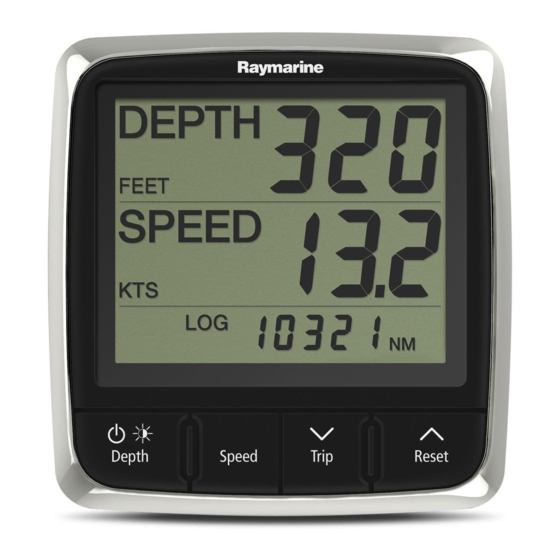
1. i50 Depth 2. i50 Speed 3. i50 Tridata The i50 instrument display range offers the following features: • Integrates with Raymarine autopilots and navigation equipment on the SeaTalk network • Surface mountable • Extra large (28 mm max) digits •... -
Page 15: Chapter 3 Planning The Installation
Chapter 3: Planning the installation Chapter contents • 3.1 Installation checklist on page 16 • 3.2 Compatible transducers on page 16 • 3.3 Typical systems on page 18 • 3.4 System protocols on page 20 • 3.5 Tools required on page 20 •... -
Page 16: Installation Checklist
The depth transducers listed below are compatible with the following instrument displays: Plan your system. • i40 Depth / i40 Bidata Obtain all required equipment and tools. • i50 Depth / i50 Tridata Site all equipment. • i70 via iTC-5 converter Route all cables. Part Drill cable and mounting holes. - Page 17 Instrument Depth, Speed and Temperature (DST) transducers The DST transducers listed below are compatible with the following instrument displays: • i40 Depth / i40 Speed / i40 Bidata • i50 Depth i50 Speed / i50 Tridata • i70 via iTC-5 converter Part number Image...
-
Page 18: Typical Systems
Wind instrument Raymarine wind vane transducer Raymarine multifunction display 12 / 24 V dc power supply Raymarine course computer (providing 12 V dc power supply to the SeaTalk network.) i50 Speed instrument i50 Depth instrument Speed transducer... - Page 19 D12374-1 SeaTalk pilot controller SeaTalk instrument displays Fluxgate compass Rudder reference Raymarine course computer (providing 12 V dc power supply to SeaTalk network.) 12 / 24 V dc power supply Raymarine AIS transceiver Raymarine SeaTalk Man over board SeaTalk to SeaTalk...
-
Page 20: System Protocols
3.4 System protocols 3.5 Tools required Your product can be connected to various products Tools required for installation and systems to share information and so improve the functionality of the overall system. These connections may be made using a number of different protocols. -
Page 21: Selecting A Display Location
Viewing angle considerations As display contrast, color and night mode performance are all affected by the viewing angle, Raymarine recommends you temporarily power up the display when planning the installation, to enable you to best judge which location gives the optimum viewing angle. -
Page 22: Product Dimensions
3.7 Product dimensions 3.8 Selecting a transducer location General speed and depth transducer location requirements When selecting a location for your transducer it is important to consider a number of factors. The transducer should be mounted within the clear water flow areas indicated by the shaded areas in the image below. -
Page 23: Chapter 4 Cables And Connections
Chapter 4: Cables and connections Chapter contents • 4.1 General cabling guidance on page 24 • 4.2 Power connection on page 24 • 4.3 SeaTalk connections on page 25 • 4.4 Transducer connections on page 26 • 4.5 iTC-5 connection on page 27 •... -
Page 24: General Cabling Guidance
Raymarine. • By a battery via the distribution panel, or • Ensure that any non-Raymarine cables are of the • From a Raymarine course computer, via a SeaTalk correct quality and gauge. For example, longer or a SeaTalk system. -
Page 25: Seatalk Ng Connections
The power supply must be protected by a 5 A fuse or a circuit breaker providing equivalent protection. Raymarine recommends that the power is connected to a SeaTalk system in such a way that the current drawn on each side of the power connection point is equal. -
Page 26: Transducer Connections
4.4 Transducer connections Item Cable color Signal name Black (Depth) Piezoceramic – i50 Depth connection Blue (Depth) Piezoceramic + Screen (Depth) 0 V (shield) Brown (Speed) Temperature 0 V Temperature White (Speed) (signal) Screen (Speed) Speed 0 V (shield) Green (Speed) -
Page 27: Itc-5 Connection
The power supply must be protected by a 5 A fuse or a circuit breaker providing equivalent protection. Raymarine recommends that the power is connected to a SeaTalk system in such a way that the current drawn on each side of the power connection point is equal. -
Page 28: Nmea2000 Connection
4.7 NMEA2000 connection SeaTalk power cables Part number Description You can either: D229 SeaTalk power cable. • Use your SeaTalk backbone and connect each NMEA2000 device on a spur, OR • connect the instrument display on a spur into an existing NMEA2000 backbone. -
Page 29: Chapter 5 Mounting
Chapter 5: Mounting Chapter contents • 5.1 Mounting on page 30 • 5.2 Front bezel on page 31 Mounting... -
Page 30: Mounting
5.1 Mounting Note: The supplied gasket provides a seal between the unit and a suitably flat and stiff Pre-mounting check mounting surface or binnacle. The gasket should be used in all installations. It may also be The product is designed to be surface mounted. necessary to use a marine-grade sealant if the Before mounting the unit, ensure you have: mounting surface or binnacle is not entirely flat and... -
Page 31: Front Bezel
5.2 Front bezel Removing the front bezel D12372-1 Note: Use care when removing the bezel. Do not use any tools to lever the bezel, doing so may cause damage. 1. Using your fingers pull the bezel away from the unit at the top and side, as shown in 2. The bezel will start to come away from the unit at the top and side. -
Page 33: Chapter 6 I50 Depth
6.4 Data master on page 35 • 6.5 Calibration on page 36 • 6.6 User Calibration - i50 Depth on page 36 • 6.7 Intermediate calibration — i50 Depth on page 37 • 6.8 Dealer calibration — i50 Depth on page 38 •... -
Page 34: I50 Depth Operation
6.1 i50 Depth operation 6.2 i50 Depth controls When connected to the relevant depth transducer, your i50 depth instrument: • Provides current depth information, in either feet (ft), metres (M) or fathoms (FA). • Records the minimum and maximum depth encountered during the period the unit is switched •... -
Page 35: Power
1. Press and hold the Power button until the unit powers on and data is displayed (approximately Checking i50 Depth software version and 2 seconds). status Note: When power to the unit is turned on the unit will switch on automatically. -
Page 36: Calibration
6.5 Calibration 6.6 User Calibration - i50 Depth User calibration options include: Before first use calibration procedures must be carried out to ensure optimum performance of the • Units for depth readings — Assigns the unit of instrument with the vessel. -
Page 37: Intermediate Calibration - I50 Depth
Intermediate calibration allows you to: appropriate depth offset value. • Check the instrument software version. • Check and if necessary set the instrument status as either Master or Repeater. Checking i50 Depth software version and status 60 5 De pth Ala rm... -
Page 38: Dealer Calibration - I50 Depth
6.8 Dealer calibration — i50 Depth Note: To exit the Dealer Calibration pages at any time, press and hold the Depth and Alarm buttons Dealer Calibration enables you to set: at the same time for approximately 2 seconds. • User calibration menu access On (default) and Off. -
Page 39: Using The Depth
8 seconds of inactivity. 1. Use the Depth button to cycle through the available depth pages. 2. From the Minimum Depth or Maximum Depth page, press and hold the Reset button for approximately 3 seconds to reset the reading. i50 Depth... -
Page 40: Alarms
/ menu. D12546-2 Instrument alarms With the relevant alarm page displayed: The alarms available for the i50 Depth and i50 1. Press the Offset and Reset buttons at the same Tridata are listed below. time to change the alarm threshold. -
Page 41: Illumination
2 seconds to display the Backlight Assigning the i50 Depth to a group page. To assign the i50 Depth as part of a group so that it LAMPS is displayed on-screen and the current can participate in group illumination follow the steps backlight level. -
Page 43: Chapter 7 I50 Speed
Chapter 7: i50 Speed Chapter contents • 7.1 i50 Speed operation on page 44 • 7.2 i50 Speed controls on page 44 • 7.3 Power on page 45 • 7.4 Data master on page 45 • 7.5 Calibration on page 46 •... -
Page 44: I50 Speed Operation
7.1 i50 Speed operation 7.2 i50 Speed controls When connected to the relevant speed or speed and temperature transducer, your i50 Speed instrument provides: • Current, maximum and average speed information, in either knots (KTS), mile per hour (MPH) or kilometers per hour (KPH). -
Page 45: Power
7.3 Power 7.4 Data master Where a system contains more than one unit Powering on the unit capable of displaying a data type, the unit physically With power to the unit turned on but the unit switched connected to the transducer must be set as the data off: master and any other units set as a repeater. -
Page 46: Calibration
7.5 Calibration 7.6 User Calibration - i50 Speed User calibration options include: Before first use calibration procedures must be carried out to ensure optimum performance of the • Units for speed readings — Assigns the unit of instrument with the vessel. measure used for speed related readings. - Page 47 Selecting a speed resolution 2. Press the Speed button until 1 of the Current Speed pages is displayed (4 presses from the From the User Calibration Menu: User Calibration entry page). 1. Press the Speed button until the Speed If SOG data is available over SeaTalk then Resolution page is displayed (2 presses from the SOG page is displayed, if SOG data is not...
- Page 48 Markers — side view The vessel speed can then be worked out by taking the distance travelled (1 nautical mile) and dividing it by the average time taken to perform the run . The resulting calculation is your average speed in knots. Selecting unit of measure for water temperature readings From the User Calibration Menu:...
-
Page 49: Intermediate Calibration - I50 Speed
7.7 Intermediate calibration — i50 Note: To exit the User Calibration pages at any Speed time, press and hold the Speed and Trip buttons at the same time for approximately 2 seconds. Intermediate calibration allows you to: • Check the instrument software version. •... - Page 50 3. Use the Timer and Reset buttons to set the run 10. If you want to carry out a second calibration run, length to the required value. press the Trip button. Default value is 1.00, the run length can be set to 11.
-
Page 51: Dealer Calibration - I50 Speed
7.8 Dealer calibration — i50 Speed 2. Use the Timer and Reset buttons to adjust the speed response to the required level. The dealer calibration procedures include: The default level is 12. The levels available are 1 to 15 with level 1 being the slowest update rate •... -
Page 52: Using The Speed
7.9 Using the speed pages i. Use the Timer or Reset buttons to change the reset option to Yes. To cycle through the speed pages follow the steps ii. Press the Speed button to reset your display below: to factory default settings. 3. -
Page 53: Using The Log, Trip And Temperature
7.10 Using the log, trip and 7.11 Using the timers temperature pages To cycle through and use the Race Timer pages and Stop Watch page follow the steps below. To cycle through the available log, trip and water temperature pages follow the steps below. Time r Time r Trip... -
Page 54: Illumination
7.12 Illumination • FLY — Flybridge • NST — Mast Adjusting the backlight level — i50 Speed • GP1 to GP5 — User defined groups The backlighting level can be accessed using the Speed button. When assigned to a group, when the backlighting of 1 unit is adjusted the backlighting level of all units During normal operation: assigned to the same group will also change. -
Page 55: Chapter 8 I50 Tridata
Chapter 8: i50 Tridata Chapter contents • 8.1 i50 Tridata operation on page 56 • 8.2 i50 Tridata controls on page 56 • 8.3 Power on page 57 • 8.4 Data master on page 57 • 8.5 Calibration on page 58 •... -
Page 56: I50 Tridata Operation
8.1 i50 Tridata operation 8.2 i50 Tridata controls When connected to the relevant transducer(s) your i50 Tridata instrument: • Provides depth information in either feet (FT) or metres (M). • Enables you to define alarm thresholds for shallow alarm, deep alarm, shallow anchor alarm and deep anchor alarm. -
Page 57: Power
8.3 Power 8.4 Data master Where a system contains more than one unit Powering on the unit capable of displaying a data type, the unit physically With power to the unit turned on but the unit switched connected to the transducer must be set as the data off: master and any other units set as a repeater. -
Page 58: Calibration
8.5 Calibration 8.6 User Calibration - i50 Tridata Before first use calibration procedures must be User calibration options include: carried out to ensure optimum performance of the • Units for depth readings — Assigns the unit of instrument with the vessel. measure used for depth related readings. - Page 59 1. Press the Speed button until the Speed Units Note: To exit the User Calibration pages at any page is displayed (1 press from the User time, press and hold the Depth and Speed buttons Calibration page) at the same time for approximately 2 seconds to return to normal operation.
- Page 60 1 point speed calibration Nautical measured mile markers When neither SOG data or any other reliable means The instrument display’s speed readings can be of estimating Speed Through the Water (STW) is calibrated using a 1 point calibration process, in most available, Nautical Measured Mile Markers can situation this is all that will be required to calibrate be used to help calibrate Log Speed.
- Page 61 3. End point (stop stopwatch) 1. Press the Speed button until the Timer Buzzer page is displayed (7 presses form the User 4. First pair of markers Calibration entry page). 5. Second pair of markers To provide a more accurate reading the vessel pe e d should make between 4 to 6 runs in both directions to allow for tide and wind conditions.
-
Page 62: Intermediate Calibration - I50 Tridata
8.7 Intermediate calibration — i50 2. Press the Trip and Reset buttons at the same time. Tridata The run length will flash. Intermediate calibration allows you to: • Check the instrument software version. • Check and if necessary set the instrument status Trip Re s e t as either Master or Repeater. -
Page 63: Dealer Calibration - I50 Tridata
8.8 Dealer calibration — i50 Tridata The dealer calibration procedures include: pe e d • User calibration menu access On (default) and Off. D12468-2 • Data source for speed — The data source can be set to SOG if the display is connected to a network Note: The displayed distance should be very close containing a GPS receiver. - Page 64 1. Press the Depth button until the Speed Source 1. Press the Depth button until the Boat Show page is displayed (1 press from the User Mode page is displayed (4 presses from User Calibration Access Menu page). Calibration Menu Access page). De pth De pth D12486-2...
-
Page 65: Using Tridata Depth
8.9 Using Tridata depth pages 8.10 Using Tridata speed pages. To cycle through the depth pages follow the steps To cycle through the speed pages follow the steps below. below. pe e d De pth De pth pe e d De pth 60 5 Re s e t... -
Page 66: Using Tridata Trip, Log, Temp And Timer
8.11 Using Tridata trip, log, temp and 8.12 Using the timers timer pages To cycle through and use the Race Timer pages and Stop Watch page follow the steps below. To cycle through the trip, log, water temperature and timer pages follow the steps below. With a timer page displayed: 1. -
Page 67: Alarms
/ menu. D12547-2 Instrument alarms With the relevant alarm page displayed: The alarms available for the i50 Depth and i50 1. Press the Trip and Reset buttons at the same Tridata are listed below. time. • Shallow depth alarm The current alarm threshold will start to flash. -
Page 68: Illumination
8.14 Illumination • FLY — Flybridge • NST — Mast Adjusting the backlight level — i50 Tridata • GP1 to GP5 — User defined groups The backlighting level can be accessed using the Depth button. When assigned to a group, when the backlighting of 1 unit is adjusted the backlighting level of all units During normal operation: assigned to the same group will also change. -
Page 69: Chapter 9 Maintaining Your Display
Chapter 9: Maintaining your display Chapter contents • 9.1 Service and maintenance on page 70 • 9.2 Condensation on page 70 • 9.3 Routine equipment checks on page 71 • 9.4 Cleaning on page 71 • 9.5 Cleaning the display case on page 72 •... -
Page 70: Service And Maintenance
Certain atmospheric conditions may cause a small components. Please refer all maintenance amount of condensation to form on the unit's window. and repair to authorized Raymarine dealers. This will not damage the unit and will clear after the Unauthorized repair may affect your warranty. -
Page 71: Routine Equipment Checks
9.3 Routine equipment checks 9.4 Cleaning Raymarine strongly recommends that you complete Best cleaning practices. a number of routine checks to ensure the correct and When cleaning this product: reliable operation of your equipment. • Do NOT wipe the display screen with a dry cloth, Complete the following checks on a regular basis: as this could scratch the screen coating. -
Page 72: Cleaning The Display Case
9.5 Cleaning the display case 9.6 Cleaning the display screen The display unit is a sealed unit and does not require A coating is applied to the display screen. This regular cleaning. If it is necessary to clean the unit, makes it water repellent, and prevents glare. -
Page 73: Chapter 10 Troubleshooting
Chapter 10: Troubleshooting Chapter contents • 10.1 Troubleshooting on page 74 • 10.2 Instrument troubleshooting on page 75 • 10.3 Power up troubleshooting on page 76 • 10.4 Miscellaneous troubleshooting on page 77 Troubleshooting... -
Page 74: Troubleshooting
All Raymarine products are, prior to packing and shipping, subjected to comprehensive test and quality assurance programs. However, if you experience problems with the operation of your... -
Page 75: Instrument Troubleshooting
10.2 Instrument troubleshooting Fault Cause Action Blank display. No power supply. • Check fuse / circuit breaker. • Check power supply. • Check SeaTalk / SeaTalk cabling and connector security. SeaTalk / SeaTalk information not being SeaTalk / SeaTalk cabling or connector •... -
Page 76: Power Up Troubleshooting
10.3 Power up troubleshooting Problems at power up and their possible causes and solutions are described here. Problem Possible causes Possible solutions The system (or part of it) does Power supply problem. Check relevant fuses and breakers. not start up. Check that the power supply cable is sound and that all connections are tight and free from corrosion. -
Page 77: Miscellaneous Troubleshooting
Check that the power source is of the correct voltage and erratic behavior. sufficient current. Software mismatch on system Go to www.raymarine.com and click on support for the (upgrade required). latest software downloads. Corrupt data / other unknown Perform a factory reset. -
Page 79: Chapter 11 Technical Support
Chapter 11: Technical support Chapter contents • 11.1 Raymarine customer support on page 80 • 11.2 Checking the software version on page 80 Technical support... -
Page 80: Raymarine Customer Support
If you are unable to resolve a problem, please During normal operation: use any of these facilities to obtain additional help. 1. i50 Depth — Press and hold the Depth and Alarm buttons at the same time for approximately Web support 4 seconds. -
Page 81: Chapter 12 Technical Specification
Chapter 12: Technical specification Chapter contents • 12.1 Technical specification on page 82 Technical specification... -
Page 82: Technical Specification
12.1 Technical specification Nominal supply voltage 12 V dc Operating voltage range 10 V dc to 16 V dc Power consumption • < 1 W Typical (Display only) • 2.4 W Maximum (Transducer connected) Current • 45 to 65 mA Typical (Display only) •... -
Page 83: Chapter 13 Spares And Accessories
Chapter 13: Spares and accessories Chapter contents • 13.1 Spares on page 84 • 13.2 SeaTalk cables and accessories on page 84 • 13.3 Converters on page 85 Spares and accessories... -
Page 84: Spares
• 1 x 5 Way connector (A06064) i50 / i60 / i70 Sun R22169 cover • 2 x Backbone terminator i50 Depth keypad R70131 (A06031) i50 Speed keypad R70130 • 1 x 3 m (9.8 ft) spur cable (A06040) i50 Tridata keypad R70132 •... -
Page 85: Converters
13.3 Converters Description Part No Notes SeaTalk Power A06049 Part number Description cable E22158 SeaTalk to SeaTalk SeaTalk A06031 Converter Terminator SeaTalk T-piece A06028 Provides 1 x spur connection SeaTalk 5–way A06064 Provides 3 x spur connector connections SeaTalk A06030 backbone extender SeaTalk to E22158... -
Page 87: Appendix A Nmea 2000 Sentences
Appendix A NMEA 2000 sentences The i50 instrument range supports the following NMEA 2000 Parameter Group Number (PGN) sentences. i50 Depth i50 Depth i50 Speed i50 Speed i50 Tridata i50 Tridata PG name Transmit Receive Transmit Receive Transmit Receive ISO Acknowl- 59392 ●... - Page 90 www.ra ym a rin e .c o m...