Agilent Technologies 1200 series User Manual
Refractive index detector
Hide thumbs
Also See for 1200 series:
- Reference manual (278 pages) ,
- User manual (184 pages) ,
- Manual (150 pages)
Table of Contents
Advertisement
Advertisement
Table of Contents

Related Manuals for Agilent Technologies 1200 series


Summary of Contents for Agilent Technologies 1200 series
- Page 1 Agilent 1200 Series Refractive Index Detector User Manual...
- Page 2 WA R N I N G contains the complete information about this document are furnished under a license the Agilent 1200 Series Refractive Index and may be used or copied only in accor- A WARNING notice denotes a Detector. It is available as Adobe Reader file dance with the terms of such license.
- Page 3 In This Guide… This manual contains user information about the Agilent 1200 Series Refractive Index Detector. The manual describes the following: Introduction to the Refractive Index Detector This chapter gives an introduction to the Refractive Index Detector. Site Requirements and Specifications This chapter provides information on environmental requirements, physical and performance specifications.
- Page 4 1200 Series RID User Manual...
-
Page 5: Table Of Contents
Installing the Refractive Index Detector Unpacking the Detector Optimizing the Stack Configuration Installing the Detector Flow Connections to the Detector Using the Refractive Index Detector Operation of the Refractive Index Detector Before Using the System 1200 Series RID User Manual... - Page 6 Introduction to the Repairing the Refractive Index Detector Using the ESD Strap Maintaining the Refractive Index Detector Detector Maintenance Procedures Flow Cell Flushing Correcting Leaks Replacing Leak Handling System Parts Replacing the Detector’s Firmware Safety Information General Safety Information 1200 Series RID User Manual...
- Page 7 Contents The Waste Electrical and Electronic Equipment (WEEE) Directive (2002/96/EC) Radio Interference Sound Emission Solvent Information Agilent Technologies on Internet 1200 Series RID User Manual...
-
Page 8: Series Rid User Manual 3
Contents 1200 Series RID User Manual... -
Page 9: Introduction To The Refractive Index Detector
Agilent 1200 Series Refractive Index Detector User Manual Introduction to the Refractive Index Detector Introduction to the Refractive Index Detector How the Detector Operates Detection Principle Flow Path Electrical Connections Instrument Layout Early Maintenance Feedback (EMF) This chapter gives an introduction to the Refractive Index Detector. -
Page 10: Introduction To The Refractive Index Detector
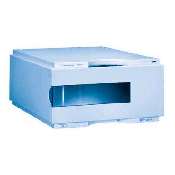
• automatic light intensity control circuit to ensure the optimum performance of the optics • integrated diagnostics for efficient troubleshooting • built-in refractive index calibration • front access to valves and capillaries for easy maintenance For specifications, see “Performance Specifications” on page 29. 1200 Series RID User Manual... - Page 11 Introduction to the Refractive Index Detector Figure 1 The Agilent 1200 Series Refractive Index Detector 1200 Series RID User Manual...
-
Page 12: How The Detector Operates
= Refractive index of medium 1 relative to medium 2 = Refractive index of medium 2 = Refractive index of medium 1 α = angle of incident light in medium 1 α =angle of refraction in medium 2 1200 Series RID User Manual... - Page 13 Factors that Affect Refractive Index The refractive index of a medium is affected by a number of factors; 1 Wavelength The refractive index varies with changes in the wavelength of the incident light beam. 2 Density 1200 Series RID User Manual...
- Page 14 The density of a medium will be affected by the following factors: • Composition (if not a pure substance) • Temperature • Pressure 1200 Series RID User Manual...
-
Page 15: Detection Principle
Introduction to the Refractive Index Detector Detection Principle Detector Design The Agilent 1200 Series refractive index detector is a differential refractometer that measures the deflection of a light beam due to the difference in refractive index between the liquids in the sample and reference cells of a single flow cell. - Page 16 This signal expressed, as nano Refractive Index Units (nRIU), corresponds to the difference between the refractive index of sample in the sample cell and the mobile phase in the reference cell. 1200 Series RID User Manual...
- Page 17 Introduction to the Refractive Index Detector lamp condenser lens incident light diodes zero glass Deflected light collimator lens sample cell reference cell mirror Figure 4 Optical Path 1200 Series RID User Manual...
-
Page 18: Flow Path
After both the purgetime and waittime have been completed the analysis will start. If the Automatic zero before analysis mode is enabled the detector output will be set to zero immediately before the analysis begins. 1200 Series RID User Manual... - Page 19 Flow path with purge valve on Figure 5 Flow Path 1 Flow in 2 Heater 3 Heat exchanger 4 Sample cell 5 Purge valve 6 Recycle valve 7 Waste container 8 Reference cell 9 Solvent bottle 1200 Series RID User Manual...
-
Page 20: G1362
ID of 0.2 mm. All other tubings (to and from the purge and the reference valve) are made of Teflon and are available as a kit (PN G1362-68709) Figure 6 G1362A Physical Plumbing Connections 1200 Series RID User Manual... - Page 21 * the T-connection in the Metal union block results in both sides of the flow cell cell (sample and reference) always being exposed to the same pressure Figure 7 Flow path with the Purge- and Recycle-Valves = OFF 1200 Series RID User Manual...
- Page 22 * the T-connection in the Metal union block results in both sides of the flow cell cell (sample and reference) always being exposed to the same pressure Figure 8 Flow path with the Purge- and Recycle-Valves = ON 1200 Series RID User Manual...
-
Page 23: Electrical Connections
ON. • The CAN bus is a serial bus with high speed data transfer. The two connectors for the CAN bus are used for internal Agilent 1200 Series module data transfer and synchronization. • One analog output provides signals for integrators or data handling systems. - Page 24 Introduction to the Refractive Index Detector Analog signal APG remote RS 232 GPIB Configuration Security Power lever Figure 9 Electrical Connections 1200 Series RID User Manual...
-
Page 25: Instrument Layout
• the plastic layers help cushion the electronic and mechanical parts from physical shock, and • the metal inner cabinet shields the internal electronics from electromagnetic interference and also helps to reduce or eliminate radio frequency emissions from the instrument itself. 1200 Series RID User Manual... -
Page 26: Early Maintenance Feedback (Emf)
Initially, no EMF limit should be set. When instrument performance indicates maintenance is necessary, take note of the values displayed by reference liquid age counters. Enter this values (or a value slightly less than 1200 Series RID User Manual... - Page 27 EMF limit, and then reset the EMF counter to zero. The next time the EMF counter exceed the new EMF limit, the EMF flag will be displayed, providing a reminder that maintenance needs to be scheduled. 1200 Series RID User Manual...
- Page 28 Introduction to the Refractive Index Detector 1200 Series RID User Manual...
-
Page 29: Site Requirements And Specifications
Agilent 1200 Series Refractive Index Detector User Manual Site Requirements and Specifications Site Requirements Physical Specifications Performance Specifications This chapter provides information on environmental requirements, physical and performance specifications. Agilent Technologies... -
Page 30: Site Requirements
Never operate your instrumentation from a power outlet that has no ground WA R N I N G connection. Never use a power cord other than the Agilent Technologies power cord designed for your region. 1200 Series RID User Manual... - Page 31 2.5 cm (1.0 inches) of space on either side and approximately 8 cm (3.1 inches) in the rear for air circulation and electric connections. If the bench should carry an Agilent 1200 Series system, make sure that the bench is designed to bear the weight of all modules.
-
Page 32: Physical Specifications
Site Requirements and Specifications Physical Specifications Table 1 Physical Specifications Agilent 1200 Series Refractive Index Detector Type Specification Comments Weight 17 kg (38 lbs) Dimensions 345 × 435 × 180 mm (width × depth × height) (13.5 × 17 × 7 inches) ±... -
Page 33: Performance Specifications
Site Requirements and Specifications Performance Specifications Table 2 Performance Specifications Agilent 1200 Series Refractive Index Detector Type Specification Comments Detection type Refractive Index Refractive index range 1.00 - 1.75 RIU, calibrated Measurement range +/- 600 x 10 Optical zeroing via set screw Optics temperature 5 °... - Page 34 Site Requirements and Specifications Table 2 Performance Specifications Agilent 1200 Series Refractive Index Detector (continued) Type Specification Comments Control and data Parameter entry, signal display, evaluation on-line help and diagnostics with the Agilent 1200 Series Control Module. Optional PCMCIA card for method, sequence and logbook storage and transfer.
- Page 35 4 s, flow 35 ° C, 1.0 mL/min LC-grade Water, restriction capillary, column compartment temperature 35 ° C, Agilent 1200 Series on-line vacuum degasser, pump and thermostatted column compartment. Instrument equilibrated for 2 hours. 1200 Series RID User Manual...
- Page 36 Site Requirements and Specifications 1200 Series RID User Manual...
-
Page 37: Installing The Refractive Index Detector
Agilent 1200 Series Refractive Index Detector User Manual Installing the Refractive Index Detector Unpacking the Detector Optimizing the Stack Configuration Installing the Detector Flow Connections to the Detector This chapter provides information on unpacking, checking on completeness, stack considerations and installation of the detector. -
Page 38: Unpacking The Detector
Damaged Packaging If the delivery packaging shows signs of external damage, please call your Agilent Technologies sales and service office immediately. Inform your service representative that the detector may have been damaged during shipment. If there are signs of damage, please do not attempt to install the detector. - Page 39 • Hand tight fitting (reorder pack with 10 pcs.) 5062-8541 Restriction capillary, 3700mm lg, 0.17mm i.d. includes: G1362-87301 • Hand tight fitting (reorder pack with 10 pcs.) 5062-8541 CAN cable 5181-1516 PEEK adapter to pump’s active inlet valve 0100-1847 1200 Series RID User Manual...
- Page 40 Installing the Refractive Index Detector Tubing Ferrule Figure 10 Interface tubing kit Parts Tubing Hand tight fitting Figure 11 Interfacing Capillary Parts Restriction capillary Hand tight fitting Figure 12 Restriction Capillary Parts 1200 Series RID User Manual...
-
Page 41: Optimizing The Stack Configuration
Installing the Refractive Index Detector Optimizing the Stack Configuration If your detector is part of a complete Agilent 1200 Series system, you can ensure optimum performance by installing the following configuration. This configuration optimizes the system flow path, ensuring minimum delay volume. - Page 42 HP- I B A ddr e ss AC power CAN Bus cable H PI B H P- I B Addr ess GPIB or LAN Analog signal to to LC- ChemStation recorder Figure 14 Recommended Stack Configuration (Rear View) 1200 Series RID User Manual...
-
Page 43: Installing The Detector
Front View of Detector 4 Connect the power cable to the power connector at the rear of the detector. 5 Connect the CAN cable to other Agilent 1200 Series modules. 6 If a Agilent ChemStation is the controller, connect either... - Page 44 7 Connect the analog cable (optional) for a chart recorder, integrator or other data collection device. 8 Connect the APG remote cable (optional) for non-Agilent 1200 Series instruments. 9 Turn ON power by pushing the button at the lower left hand side of the detector.
- Page 45 Installing the Refractive Index Detector The detector was shipped with default configuration settings. To change these settings see N O T E “Setting the 8-bit Configuration Switch” in the Service Manual. 1200 Series RID User Manual...
-
Page 46: Flow Connections To The Detector
This is to avoid breakage due to subambient conditions. 1 Press the release buttons and remove the front cover to 2 Locate the in, waste and recycle ports. gain access to the interface port area. Recycle Waste 1200 Series RID User Manual... - Page 47 Remove all blanking plugs from all outlet ports (waste & recycle) of the detector to avoid potential damage to the flow cell, if the recycle valve is accidentally switched to one of these ports, while flow is applied to the detector. 1200 Series RID User Manual...
- Page 48 (e.g. in the solvent compartment). This will maintain a slight pressure in the sample cell. Route the tubing behind the front covers of the Agilent 1200 Series modules in the stack. 8 Establish flow and observe if leaks occur. 9 Replace the front cover.
-
Page 49: Using The Refractive Index Detector
Agilent 1200 Series Refractive Index Detector User Manual Using the Refractive Index Detector Before Using the System Refractive Index Detector Control Refractive Index Detector Settings Refractive Index Detector More Settings Running a Checkout Sample Checking Baseline Noise and Drift This chapter provides information on how to set up the detector for an analysis and explains the basic settings. -
Page 50: Operation Of The Refractive Index Detector
(when available in the system) and the pump. Solvents containing volatile ingredients will slightly lose these. Therefore priming of the pumping system is required before starting an application. 1200 Series RID User Manual... -
Page 51: Refractive Index Detector Control
How To Get There: The Agilent 1200 RID Control dialog box is displayed when you select More RID... from the Instrument menu (More RID... is available in Full Menus only) and select Control... from the More RID... submenu. 1200 Series RID User Manual... - Page 52 • Analog Output Range: The Analog Output Range group allows you to select the voltage ranges of the analog output of the refractive index detector. Select 0.1 V to set the full-scale output to 0.1 volts. Select 1 V to set the full-scale output to 1 volt. 1200 Series RID User Manual...
-
Page 53: Refractive Index Detector Settings
The following operating instructions were generated using the Agilent B.01.03 ChemStation as operating software. How To Get There: The Agilent 1200 RID Signal dialog box is displayed when you select Setup RID Signal from the Instrument menu. 1200 Series RID User Manual... - Page 54 Negative or Positive. • Automatic Recycling: This parameter can be used to select between automatic recycling of the eluent (on) or directing the eluent to the waste outlet of the RID (off) after the run. 1200 Series RID User Manual...
-
Page 55: Refractive Index Detector More Settings
Stoptime Stoptime enables you to set a time at which the RID stops an analysis. If the RID is used with other Agilent 1200 Series modules, the RID stoptime stops the RID only and does not stop any other modules. - Page 56 • Analog Output: If the Analog Output is used a zero offset (limits between 1 and 99%) can be selected to enable the display of negative peaks. The attenuation settings helps to keep all peaks on scale. Choose the appropriate setting from the list. 1200 Series RID User Manual...
- Page 57 This should only be used if the content of the reference cell is expected to degrade during a run. The automatic purge will be finished before the autozero is performed and before the injection is done. 1200 Series RID User Manual...
-
Page 58: Running A Checkout Sample
Using the Refractive Index Detector Running a Checkout Sample This chapter describes the check out of the Agilent 1200 Series refractive index detector using the Agilent isocratic checkout sample. When required If you want to checkout the detector Hardware required... - Page 59 Injection volume 20 µl Column compartment temperature 25 ° C Optical unit Temperature 35 ° C Polarity Positive Peak Width (Response time) 0.2 minutes (4 seconds, standard) 2 Set the RID setpoints according to Figure 1200 Series RID User Manual...
- Page 60 Using the Refractive Index Detector Figure 20 RID Check Out Sample Parameters 3 Turn the heater ON and purge the detector reference cell for 20 minutes as shown in Figure 1200 Series RID User Manual...
- Page 61 5 If you are using the Control Module in place of the Agilent ChemStation enter the Plot function and select Ref.Index, set a time range of 10 minutes and the RID signal from -4000 to 40000 nRIU. 1200 Series RID User Manual...
- Page 62 Only similar zooming factors in the display of a chromatogram will lead to similar looking results. The resulting chromatogram is shown in Figure Figure 22 Isocratic Standard Sample Chromatogram 1200 Series RID User Manual...
-
Page 63: Checking Baseline Noise And Drift
Using the Refractive Index Detector Checking Baseline Noise and Drift This chapter describes checking the baseline noise and drift for the Agilent 1200 Series refractive index detector. When required If you want to checkout the detector Hardware required LC system with G1362A RID... - Page 64 The optical unit temperature must be set at least 5 ° C above ambient conditions. Therefore if N O T E ambient temperature is above 30 ° C higher values for Optical unit Temperature and Column compartment temperature must be set. 1200 Series RID User Manual...
- Page 65 If you are not using the Agilent ChemStation go to step 10. N O T E 4 Edit the Agilent ChemStation method (Method and Run Control- Method Edit Entire Method). 5 Specify the report style Performance + Noise as shown in Figure 24 1200 Series RID User Manual...
- Page 66 Using the Refractive Index Detector Figure 24 RID Baseline Check Out Report 6 Set the noise determination time range to 0 - 20 minutes as shown in Figure 1200 Series RID User Manual...
- Page 67 Using the Refractive Index Detector Figure 25 RID Baseline Check Out Noise Ranges 1200 Series RID User Manual...
- Page 68 10 If you are using the Control Module in place of the Agilent ChemStation enter the Plot function and select Ref.Index, set a time range of 20 minutes and the RID signal from -200 to 200 nRIU. 11 The Agilent ChemStation report in shown in Figure 1200 Series RID User Manual...
- Page 69 For the Control Module Rescale the plot and measure the baseline noise and drift on the screen. If a printer is configured for the Agilent 1200 Series instrument the plot can be printed by pressing the m key and selecting Print Plot.
- Page 70 • Variations in the optics or eluent temperature • Pressure fluctuations in the sample cell • The quality of the water used • Air bubbles in the flow cell “Refractive Index Detector Control” on page 47. 1200 Series RID User Manual...
-
Page 71: Optimizing The Refractive Index Detector
Agilent 1200 Series Refractive Index Detector User Manual Optimizing the Refractive Index Detector Refractive Index Detector Optimization Potential Causes for Baseline Problems Detector Equilibration This chapter provides information on how to optimize the detector. Agilent Technologies... -
Page 72: Refractive Index Detector Optimization
Confirm that the instrument is free from leaks by performing the Agilent 1200 Series diagnostic pressure test (for the high pressure parts of the system between pump and column). Ensure that the connections from the on-line vacuum degasser to the pump and the detector inlet, waste and recycle connections are air tight. - Page 73 (use adapter 0100-1847, which is delivered with the accessory kit of the detector). 12 Consider solvent changes with time 1200 Series RID User Manual...
-
Page 74: Potential Causes For Baseline Problems
Drift Excessive drift is an indication for a general system or environmental instability (system or laboratory might not be thermally stable, control instrument and laboratory temperature). Verify that the solvent properties are 1200 Series RID User Manual... -
Page 75: Detector Equilibration
Switch valves and settings only when needed. Do not expose the detector to draft of air or to vibrations). A change of any of these parameters may require a considerable amount of time for re-equilibration. 1200 Series RID User Manual... - Page 76 Optimizing the Refractive Index Detector 1200 Series RID User Manual...
-
Page 77: Troubleshooting Overview
Agilent 1200 Series Refractive Index Detector User Manual Troubleshooting Overview Overview of the Detector’s Indicators and Test Functions Status Indicators This chapter gives an overview about the troubleshooting and diagnostic features. Agilent Technologies... -
Page 78: Overview Of The Detector's Indicators And Test Functions
Optical balance allows the balance of light falling on the light receiving diodes to be restored. The sample and reference cells must both be fully purged before the procedure is started, see “Optical Balance” in the Service Manual). 1200 Series RID User Manual... -
Page 79: Status Indicators
The power supply indicator is integrated into the main power switch. When the indicator is illuminated (green) the power is ON. Detector Status Indicator The detector status indicator indicates one of four possible detector conditions: 1200 Series RID User Manual... - Page 80 • An error condition is indicated when the status indicator is red. An error condition indicates the detector has detected an internal problem which affects correct operation of the detector. Usually, an error condition requires attention (e.g. leak, defective internal components). An error condition always interrupts the analysis. 1200 Series RID User Manual...
-
Page 81: Repairing The Refractive Index Detector
Agilent 1200 Series Refractive Index Detector User Manual Repairing the Refractive Index Detector Introduction to the Repairing the Refractive Index Detector This chapter provides general information on repairing the detector. Agilent Technologies... -
Page 82: Introduction To The Repairing The Refractive Index Detector
The security lever at the power input socket prevents the detector cover from being removed when line power is still connected. These repairs are described in “Exchanging Internal Parts” in the Service Manual. 1200 Series RID User Manual... - Page 83 C A U T I O N to prevent damage always use an ESD protection (for example, the ESD wrist strap from the accessory kit of another Agilent 1200 Series module) when handling electronic boards and components (see “Using the ESD Strap”...
-
Page 84: Using The Esd Strap
Electronic boards are sensitive to electronic discharge (ESD). In order to prevent damage, always use an ESD strap supplied in the standard accessory kit of other Agilent 1200 Series modules when handling electronic boards and components. 1 Unwrap the first two folds of the band and wrap the exposed adhesive side firmly around your wrist. -
Page 85: Maintaining The Refractive Index Detector
Agilent 1200 Series Refractive Index Detector User Manual Maintaining the Refractive Index Detector Detector Maintenance Procedures Flow Cell Flushing Correcting Leaks Replacing Leak Handling System Parts Replacing the Detector’s Firmware This chapter describes the maintenance of the detector. Agilent Technologies... -
Page 86: Detector Maintenance Procedures
If flow cell is contaminated. Leak sensor If leak has occurred. Check for leaks. drying Leak handling f broken or corroded. Check for leaks. System replacement Replacing the If not up to date or corrupted. detector’s Firmware 1200 Series RID User Manual... -
Page 87: Flow Cell Flushing
The strong solvent used may be dangerous and proper attention to safety should be C A U T I O N given. Do not exceed the flow cell pressure limit of 5 bar (0.5 MPa). N O T E 1200 Series RID User Manual... -
Page 88: Correcting Leaks
4 Observe the interface ports and the valve area for leaks and correct, if required. 5 Close the service door. 6 Replace the front cover. Valves and tubing Service door Leak sensor Figure 30 Observing for Leaks 1200 Series RID User Manual... -
Page 89: Replacing Leak Handling System Parts
4 Insert the leak funnel with the tubing in its position. 5 Insert the leak funnel into the leak funnel holder. 6 Replace the front cover. Leak funnel Leak funnel holder Leak tubing Leak sensor Figure 31 Replacing Leak Handling System Parts 1200 Series RID User Manual... -
Page 90: Replacing The Detector's Firmware
Service Manual to add the recalibration parameters into the board’s memory. 4 If detector main board was replaced, re-enter the serial number information of the module through the user interface as described in the Service Manual. 1200 Series RID User Manual... - Page 91 Agilent 1200 Series Refractive Index Detector User Manual Safety Information General Safety Information The Waste Electrical and Electronic Equipment (WEEE) Directive (2002/96/EC) Radio Interference Sound Emission Solvent Information Agilent Technologies on Internet This chapter provides additional information on safety, legal and web.
-
Page 92: A Safety Information
Make sure that only fuses with the required rated current and of the specified type (normal blow, time delay, and so on) are used for replacement. The use of repaired fuses and the short-circuiting of fuse holders must be avoided. 1200 Series RID User Manual... - Page 93 When working with solvents please observe appropriate safety procedures (e.g. goggles, safety gloves and protective clothing) as described in the material handling and safety data sheet by the solvent vendor, especially when toxic or hazardous solvents are used. 1200 Series RID User Manual...
- Page 94 A caution alerts you to situations that could cause a possible loss of data. Do not C A U T I O N proceed beyond a caution until you have fully understood and met the indicated conditions. 1200 Series RID User Manual...
-
Page 95: The Waste Electrical And Electronic Equipment (Weee) Directive (2002/96/Ec)
I, this product is classed as a “Monitoring and Control instrumentation” product. Do not dispose off in domestic household waste To return unwanted products, contact your local Agilent office, or see www.agilent.com for more information. 1200 Series RID User Manual... -
Page 96: Radio Interference
If test and measurement equipment is operated with equipment unscreened cables and/or used for measurements on open set-ups, the user has to assure that under operating conditions the radio interference limits are still met within the premises. 1200 Series RID User Manual... -
Page 97: Sound Emission
This product has a sound pressure emission (at the operator position) < 70 dB. • Sound Pressure Lp < 70 dB (A) • At Operator Position • Normal Operation • According to ISO 7779:1988/EN 27779/1991 (Type Test) 1200 Series RID User Manual... -
Page 98: Solvent Information
• Halogenated solvents or mixtures which form radicals and/or acids, for example: → 2COCl 2CHCl + 2HCl This reaction, in which stainless steel probably acts as a catalyst, occurs quickly with dried chloroform if the drying process removes the stabilizing alcohol. 1200 Series RID User Manual... - Page 99 For example, a 1-% solution of acetic acid in methanol will attack steel. • Solutions containing strong complexing agents (for example, EDTA, ethylene diamine tetra-acetic acid). • Mixtures of carbon tetrachloride with 2-propanol or THF. 1200 Series RID User Manual...
-
Page 100: Agilent Technologies On Internet
For the latest information on products and services visit our worldwide web site on the Internet at: http://www.agilent.com Select “Life Sciences & Chemical Analysis Solutions” It will provide also the latest firmware of the Agilent 1200 Series modules for download. 1200 Series RID User Manual... - Page 101 GLP, operation of the detector, setting the test conditions, Cleaning the Detector, GLP features, compliance, GPIB, control, leak handling system replacing, 1200 Series RID User Manual...
- Page 102 Snell’s Law, line voltage and frequency, solvent and waste reservoirs, operation temperature, Solvent Information, power consumption, solvents, 68, safety standards, weight and dimensions, Power Consideration, 1200 Series RID User Manual...
-
Page 104: The Agilent 1200 Series Refractive Index
In This Book This manual contains user information about the Agilent 1200 Series Refractive Index Detector. The manual describes the following: • introduction to the RI detector and theory of operation, • site requirements and specifications, • installing the RI detector, •...