Table of Contents

Related Manuals for Panasonic SP-DR04


Summary of Contents for Panasonic SP-DR04
-
Page 1: Digital Video Recorder
INSTRUCTION MANUAL (SP-DR_Ver. 1.1_120404) H.264 Video Compression Digital Video Recorder About this user guide Before installing and using this unit, please read this user guide carefully. Be sure to keep it handy for later reference... -
Page 2: Safety Precautions
Safety Precautions Explanation of Graphical Symbols This symbol indicates the presence of important operating and maintenance (servicing) instructions in the literature accompanying the product. This symbol indicates the presence of uninsulated ”dangerous voltage” within the product’s enclosure that may be of sufficient magnitude to constitute a risk of electric shock to persons. - Page 3 These precautions must be followed for safety reasons. Warning Do not use if the unit emits smoke, strange sounds are heard, or odor is emitted. Make sure the power cable is not damaged. Make sure there is no dust accumulation on the power plug or the outlet. Disassembly prohibited Do not place any foreign objects inside the unit.
- Page 4 Warning Installation and servicing should be performed only by qualified and experienced personnel. Turn off the power of the DVR when connecting cameras, audio or sensor cables. The manufacturer is not responsible for any damage caused by improper use of the product or failure to follow instructions for the product.
-
Page 5: Product Components
Product Components The package contains the main unit and its components as specified below. When you purchase the unit, Please check to ensure the components specified below are included. DVR Set Client Software CD Mouse Remote Control Battery1.5V (AAA x 2EA) Quick Guide Adaptor &... - Page 6 Left button: SELECT function ② Wheel: MOVEMENT function on a drop-down menu Mounting the hard disk drive For SP-DR04 : Unfasten the cover of the unit. Mount the HDD to the supplied HDD bracket using the supplied 4 screws. 3. Fix the HDD on the bottom of the system using 4.
- Page 7 For SP-DR08 & SP-DR16 : 1. Before installing bracket and screws onto 2. After installing bracket and screws onto HDD. 3. Installation HDD and Bracket onto base 4. Installation HDD and Bracket onto base case (Inside) case (Outside) 5. After connecting power cable and data 6.
-
Page 8: Compatible Hdd Models
Compatible HDD Models Brand Model Size SATA Type Buffer Seagate ST2000VM002 2 TB SATA 2 5900 RPM 64 MB ST2000DL003(barracuda green) 2 TB SATA 3 5900 RPM 64 MB ST32000641AS(Barracuda XT) 2 TB SATA 3 7200 RPM 64 MB ST1000DM003 1 TB SATA 3 7200 RPM... - Page 9 WD20EADS 2 TB SATA 2 5400 RPM 32 MB WD20EURS 2 TB SATA 2 64 MB WD10EURX(63FH1Y0) 1 TB SATA 3 5400 RPM 64 MB WD10EZRX(00A8LB0) 1 TB SATA 3 5400 RPM 64 MB WD10EARS(00Y5B1 Caviar Green) 1 TB SATA 3 5400 RPM 64 MB WD10EVDS(63U8B1)
-
Page 10: Specifications
Specifications ITEM SP-DR04 SP-DR08 SP-DR16 Channel Input Level Composite, 1.0Vp-p, 75ohm Input Signal Format NTSC/PAL Video Video Loss Check 1 (Main Display) Output CVBS 1 (Main or Spot) 2 (Main Display & Spot Display) Input & Output 4 CH Line input & 1 CH Line output... - Page 11 Huge Backup Yes (up to 24 hours) Network Video & Still Image Menu Display User I/F Input Method Front buttons, Remote control, Mouse, Keyboard controller Console 1 RS-232C (9pin D-SUB connector) Serial port PTZ control & Keyboard DVR control 1 RS-485 Termination Dynamic DNS Yes (Free DDNS)
-
Page 12: Table Of Contents
Table of Contents Name, Function and Connection ..................... 15 2-1. Front Panel ............................15 2-2. Rear Panel ............................17 2-3. Remote control ..........................18 Setting up the DVR .......................... 19 3-1. Setup – Main Screen ......................... 19 3-2. Setup – Display Mode ........................21 3-3. - Page 13 6-1. Still Image backup onto USB flash memory ..................49 6-2. Video backup onto USB flash memory ....................49 6-3. Transferring still images or video from the ARCHIVE list ..............50 6-4. Playback of Backup Video ......................... 51 7. Upgrading Firmware ........................... 52 8.
- Page 14 Main Features H.264 Video compression Reliable File system Individual channel operation Motion detaction Easy scheduler Easy software upgrade Easy and simple user interface Automatic video input and video loss detection Covert camera operation provides enhanced security Various ways of network access via Network client software, Web-viewer, UMS(Multi-site monitoring software) and Mobile Viewer Instant and convenient backup via USB flash drive, DVD-R(only for SP-DR08/ SP-DR16) or network...
-
Page 15: Name, Function And Connection
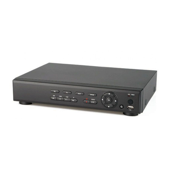
1. Name, Function and Connection 2-1. Front Panel The following information will help you to operate the front panel controls. SP-DR04 SP-DR08 / SP-DR16 Table2.1.1. Indication lamps Name Description Indicating that the system is accessing the hard disk. Indicating that the system is switched on. - Page 16 Press to rewind the footage in playback mode. Press to fast forward the footage in playback mode. In live display mode : Press to select audio mode. In playback mode : Jump/Step backward. The playback position moves 60 seconds backward. In live display mode : Press to enable/disable ALARM operation.
-
Page 17: Rear Panel
2-2. Rear Panel SP-DR04 SP-DR08 SP-DR16 Table 2.2.1. Rear panel connections Connection Purpose Connectors for video input. (NTSC/PAL) VIDEO IN Video out:. Main display CVBS Spot out: One channel screen with an event image. Connector for VGA monitor. For engineering use only. (only for SP-DR08/ SP-DR16) RS-232 4 connectors for audio input. -
Page 18: Remote Control
RS-485 control terminal RS-485 Connect adaptor POWER SOCKET (SP-DR04 : DC 12V 3A, SP-DR08/SP-DR16 : DC 12V 5A) COOLING FAN 2-3. Remote control ① ID: When a remote control ID number is set in DVR, press it before number. ② REC: To start and stop manual recording. -
Page 19: Setting Up The Dvr
2. Setting up the DVR The following sections detail the initial setup of a DVR. 3-1. Setup – Main Screen When booting a system at first, the following messages display. After initializing, select a language and set the time. To enter the setup menu, select a right button of the mouse or press the SETUP button on the remote control. -
Page 21: Setup - Display Mode
3-2. Setup – Display Mode Press the SETUP button and select DISPLAY. Then, the DISPLAY menu displays as picture below. Navigate through the menu items using the mouse or the control button ( ◀ ▲ ▶ ▼ ) on the remote control and change the value of the menu item. - Page 22 NAME Set the channel name. Press the right square button and set the ◀ channel name and select OK using the mouse or the control button ( ▲ ▶ ▼ ) on the remote control. The name can be made by 10 characters at most.
-
Page 23: Setup - Recording Mode
FRAME RATE Set the frame rate for the specified channel. The sum of the frame rate values from each channel cannot exceed the maximum frame rates for a specific recording resolution. Typical values of the maximum frame rate for video are as follows. Half D1 SP-DR04 100fps SP-DR08 200fps 100fps SP-DR16... -
Page 24: Recording Schedules
QUALITY Select the recording quality for the specified channel. Options are: LEVEL 1 (Low), 2, 3, 4 and 5 (High) RECORDING Assign the recording mode for each channel. Options are: Continuous, By Motion, By Sensor, By Schedule or Disable. Enable setting up to 4 sensors for the specified channel using the SENSOR ◀... -
Page 25: Setup - Device Mode
3-4. Setup – Device Mode Press the SETUP button and enter the password. Select DEVICE icon and press SEL button to enter the setup menu item. Then, the device menu is displayed as picture below. Navigate through the menu items ◀... -
Page 26: Alarm-Out
3-4-1. ALARM-OUT Figure 3.4.2. ALARM-OUT setup screen Table 3.4.2. Menu item in ALARM-OUT Setup screen Item Description Available NO is just one (1). ALARM OUT SENSOR IN Enable setting up to 1 camera of 4 cameras for each alarm. MOTION ON Enable setting up to 1 camera of 4 cameras for each alarm. VIDEO LOSS Set the alarm out when any channel has no video. -
Page 27: Controller & Ptz Setup
Set the dwell time for the display of the event activated channel. SPOT EVENT (3-10sec) DWELL TIME Enable/disable sequential display of spot channel in full screen. SEQUENCE If select ON, spot channel selection screen is displayed. Set the dwell time for the spot channel display.(3-10sec) SEQ-DWEL TIME Select a channel for spot monitoring using the mouse or the control SPOT CHANNEL... -
Page 28: Motion Zone Setup
3-4-4. Motion Zone Setup ◀ ▲ ▶ ▼ Select MOTION ZONE using the mouse or the control button ( ) on the remote control and select either PARTIAL ZONE or FULL ZONE using the mouse control. The default value is FULL ZONE. If FULL ZONE is selected, the motion setting screen is not displayed. -
Page 29: Setup - Storage Mode
3-5. Setup – Storage Mode Press the SETUP button and select STORAGE icon. Then, the STORAGE menu is displayed as picture below. Navigate through the menu items using the mouse or the control button ( ◀ ▲ ▶ ▼ ) on the remote control and change the value of the menu item. - Page 30 Enable/disable recording limit. RECORDING LIMIT RECORDING LIMIT DAYS Set the recording limit days.(1- 90 days) When setting to 1 day, the data will remove by the hour. Set the alarm and beep by setting HDD temperature limit. S.M.A.R.T.
-
Page 31: Setup - System Mode
3-6. Setup – System Mode Press the SETUP button and select SYSTEM icon. Then, the SYSTEM menu is displayed as picture below. Navigate through the menu items using the mouse or the control button ( ◀ ▲ ▶ ▼ ) on the remote control and change the value of the menu item. - Page 32 Select the display language using the mouse or the control button ( ◀ ▲ ▶ LANGUAGE ▼ ) on the remote control. Once a language is selected, the display language changes. (English, Korean, Japanese, SP Chinese, TR Chinese, Czech, Finnish, French, Greek, Italian, Dutch, Norse, Russian, Spanish, Turkish, Polish, Danish, Croatian, German, Portuguese, Farsi and so on) ◀...
- Page 33 CAUTION: - Do not set the start time to 23:00 for DLS. - DLS can’t be applied if the date of BEGIN and END is the same. Enable/Disable remote access through network client software. CLIENT ACCESS NTP is an abbreviation for Network Time Protocol, which is for synchronizing the clocks of computer systems over variable-latency data networks.
- Page 34 IP NOTIFICATION: Enable/disable sending e-mail when the IP address of your DVR is changed. EVENT ALARM: Enable/disable sending e-mail reports on the channel that triggered the alarm when an alarm event is triggered. MAIL BY S.M.A.R.T.: Enable/disable sending e-mail reports when S.M.A.R.T.
-
Page 35: Setup - Security Mode
3-7. Setup – SECURITY Mode Press the SETUP button and select SECURITY icon. Then, the SECURITY menu is displayed as picture below. Navigate through the menu items using the mouse or the control button ( ◀ ▲ ▶ ▼ ) on the remote control and change the value of the menu item. - Page 36 Options are ADMIN, NETWORK, USER1, USER2 and USER3. USER PASSWORD ◀ ▲ Select USER PASSWORD using the mouse or the control button ( ▶ ▼ ) on the remote control and press SEL button. Select user type and enter the current password. And, enter a new password, enter the same password again to confirm and select OK.
-
Page 37: Setup - Network Mode
3-8. Setup – Network Mode Press the SETUP button and select NETWORK icon. Then, the network menu is displayed as picture below. Navigate through the menu items using the mouse or the control button ( ◀ ▲ ▶ ▼ ) on the remote control and change the value of the menu item. -
Page 38: Port, Network Audio Port And Web Port
3-8-1. Port, Network Audio Port and Web Port When you connect one or more DVRs to a network through an IP sharing device, each device must have a unique TCP port number for access to each unit from outside the LAN. Also, the IP sharing device must be configured for port forwarding so when each port is accessed on the IP sharing device, it will forward to the appropriate DVR. -
Page 39: Ddns
3-8-3. DDNS User can use the function to connect to a network with a domain name. When it selects a Sever 1, user can select one type among three DDNS Servers which be supporting for free. (okddns.com for Korea, ddnscenter.com for USA and bestddns.com for other area including EU) The DDNS interval can be set from 5 to 60 minutes. -
Page 40: Setup - Config Mode
3-9. Setup - CONFIG Mode Press the SETUP button and select CONFIG icon. Then, the config menu is displayed as picture below. Navigate through the menu items using the mouse or the control button ( ◀ ▲ ▶ ▼ ) on the remote control and change the value of the menu item. -
Page 41: Quick Setup
3-10. Quick Setup Press the SETUP button and select QUICK SETUP icon. Then, the QUICK SETUP menu is displayed as picture below. Navigate through the menu items using the mouse or the control button ( ◀ ▲ ▶ ▼ ) on the remote control and change the value of the menu item. -
Page 42: Live, Search And Playback
3. Live, Search and Playback 4-1. Live Viewing Screen In the Live screen, video inputs from the cameras are displayed as they are configured in the Display Setup screen. Various on-screen display (OSD) symbols, which indicate the status of the DVR, are described in Table 4.1.1. - Page 43 Sequence button. Click this button to use a sequence function. Manual Record button. Click this button to record at once. Alarm-out function On/Off button. An alarm is stopped and an alarm setup lamp is right out when it clicks this button during the alarm is in progress. Click the split screen icon to change the current split screen mode using the mouse or SEL button.
-
Page 44: Search Screen
4-2. SEARCH Screen To enter the search screen, select SEARCH menu on the screen using the mouse or press SEARCH icon on live screen. Figure 4.2.1. Search Screen There are 7 ways of search menu such as TIMELINE, EVENT, GO TO FIRST TIME, GO TO LAST TIME, GO TO SPECIFIC TIME, ARCHIVE and LOG on the screen. -
Page 45: Event Search
When it clicks a Timeline menu, user can see a calendar which has recording data. Select a specific date and time. Use a drag-and-drop function of the mouse control. User can select a specific minutes using a button in the above red box. Press a PLAY button after setting a specific time. Press the PREV to return to the SEARCH window. -
Page 46: Archive Search
User can search for video data from a specific instance by setting the date and time in the Go To Specific Time menu. Use the mouse or the control button ( ◀ ▲ ▶ ▼ ) on the remote control to change the date and time value and press the PLAY button after setting. -
Page 47: Play Mode
4-3. Play mode During playback of a recorded event, the mode changes from SEARCH to PLAY. While in PLAY mode, you may return to the SEARCH screen by pressing the X button on the status bar or the ESC button of a remote control. -
Page 48: Ptz Control
5. PTZ Control To control the PTZ functions of the camera, select PTZ menu on the screen using the mouse. Select the item you wish to control the PTZ camera and control them using the mouse or the control button ( ◀... -
Page 49: Back Up
Table 5.2. Description of RS-485 port Data + Data - 6. Back up 6-1. Still Image backup onto USB flash memory Still images can be captured and archived onto the USB stick or hard drive in live mode or while playing back recorded video. -
Page 50: Transferring Still Images Or Video From The Archive List
4. After selecting the channels and setting of the duration, the system will start to archive the data to the selected media. Figure 6.2.1. Video Archiving and Backup Screen 6-3. Transferring still images or video from the ARCHIVE list The stored data onto hard drive will be found in the ARCHIVE list in SEARCH window. User can back up still images or video into the storage device from the ARCHIVE list. -
Page 51: Playback Of Backup Video
Figure 6.3.1. Archive Search Screen 6-4. Playback of Backup Video NSF format: NSF format video can be played back by the player (the HD player) that the DVR copies on USB thumb drive with video. Two folders are copied on USB thumb drive - BACKUP DATA: NSF format video file and INDEX file for a title file of date and time - HD PLAYER: Exclusive video viewer. -
Page 52: Upgrading Firmware
7. Upgrading Firmware In order to upgrade, the firmware upgrade file must first be downloaded and copied into the USB memory stick. Create a new folder in the USB memory stick and name it “upgrade”. Copy the firmware upgrade file “xxxxxx.bin”... - Page 53 4. You could see the following warning message if you don’t pull out the USB memory stick. Remote Firmware Upgrade User can upgrade the firmware via Network as follows. 1. Go to the Remote Setup menu on the UMS Single, UMS Multi or Web Viewer. 2.
- Page 54 3. Go to the Remote Upgrade menu. Then, you can see the current F/W version as follows. To upgrade a new F/W, insert the F/W in your PC and press the UPGRADE button. 4. Then, you can see the following progress bar and it would be taken around 150 seconds to upgrade. 5.
-
Page 55: Network Access Using The Exclusive Network Viewer, Ums Single
8. Network access using the Exclusive network viewer, UMS single The DVR provides a live remote monitoring feature. Remote monitoring requires installation of the network viewer on your PC. NOTICE In a high bandwidth network, a maximum of four users can access one DVR simultaneously. In a low bandwidth network it is recommended that only one user access the DVR at a time. -
Page 56: Live Monitoring Mode And Functions
8-3. Live monitoring mode and functions. Button Function Description Displays the current date and time. DATE & TIME CONNECT/DISCONNECT Connect/disconnect network connection. Switches the live mode to search mode. SEARCH Select a channel and screen display DISPLAY MODE mode. Control the PAN/TILT/ZOOM/FOCUS PAN/TILT/ZOOM/ FOCUS features on the remote camera. -
Page 57: Bi Directional Audio
Operations of the display mode of the main screen Single channel display - Click the one of channel button or double-click the channel screen. QUAD/-screen display - Click the QUAD button to switch to quad-screen display Full screen display - Click the maximize button to display only screen and hidden the operation panel. Image capture of live screen Still-image of live screen can be captured and saved as BMP or JPEG file. -
Page 58: Remote Search Mode And Functions
8-5. Remote search mode and functions Button Function Description Displays the recording time of the data DATE & TIME selected on the time bar at the bottom of the main user interface. Disconnect network connection.. DISCONNECT Switches the search mode to live mode. LIVE Capture a still image from live screen. - Page 59 Searching and playing video in the remote DVR Video recorded in the remote DVR or Video recorded on the PC can be searched and played back. 1. Connect the network to the remote DVR and press SEARCH button. Then the mode is changed from the live mode to the search mode.
-
Page 60: Pc System Configuration
Backup of video in the remote DVR Video recorded in the remote DVR cab be backed up on the PC HDD as AVI format. 1. Connect the network to the remote DVR and play the video recorded in the remote DVR. 2. - Page 61 Setting General Security Option, Save Path, Miscellaneous. Security Option: Set a password for security options. When you access any of the selected functions, you will need to enter the password. Save Path: Specify the location to record for backup and still image capture. Automatic reconnection: If a user selects this function, the client S/W will automatically try to connect to the previously connected IP address if the network connection is lost.
- Page 62 Search and check the recorded log data. Setting Record Set the recording conditions and select channels to record. Select the local disk to use and the amount of disk space you want to allow the program to use for recording.
-
Page 63: Network Access Using The Exclusive Network Viewer, Ums Multi
9. Network access using the Exclusive network viewer, UMS multi 9-1. Overview The UMS Multi-Client is a multiple site monitoring client software with; video, audio, and alarm signals from the DVRs over networks. The UMS Multi-Client does not limit the number of DVR units to register. The program displays to up 256 live videos on one display and even playback videos window on the same or another display monitor. -
Page 64: Live Window
4. The setup status screen is displayed. 5. After the installation is completed, “UMS Multi Client” icon displays on the desktop screen. 9-4. Live Window When installation is completed, double click the “UMS Multi Client” icon on your desktop to start the program. - Page 65 THUMBNAIL REFRESH: Click this icon to refresh and renew thumbnail image of every connected site. SITE ADDITION: Click this icon to open ‘Site Addition’ window. SITE DELETE: Click this icon to delete site from the index window, after disconnect a site. NET FINDER: Select the site from the index window and SITE MANAGEMENT click this icon to modify the information of specific site.
-
Page 66: Search And Playback Window
9-5. Search and Playback Window 9-5-1. Main user interface You can access to search window by clicking the search icon (Local Playback / Remote Playback) on the upper left of Live Window. 9-5-2. Main control panel Button Description Click this icon to run a playback window to search and play videos that are recorded in local PC. - Page 67 Click this icon to capture a still image. CAPTURE EVENT LIST Click this icon to set the beginning time for backup of the MARK IN recorded video in AVI format. Click this icon to set the ending time for backup of the recorded MARK OUT video in AVI format.
-
Page 68: Setup Of Ums Multi Client
9-6. Setup of UMS Multi Client Click the setup icon to setup the configuration of UMS Multi Client software. The Setup window displays. 9-6-1. General 9-6-1-1. Security Option: Set a password for security options. Select security options and set a password. Then when you access any of selected functions, you need to enter the password. -
Page 69: Record
9-6-3. Record 9-6-3-1. Record setup: You can set the recording conditions for Always, Event, or Auto record. And you can also select target DVR/DVRs and channel/channels. When you set the recording condition to event, you can set event for motion or alarm with duration. -
Page 70: About
9-6-6. About “About” provides network client version information. 9-7. Remote Setup The menu settings for the DVR unit can be set from a PC, via network. Put the cursor of the mouse on the channel which is connected to the site and press the right. Then the following window is displayed. - Page 71 9-7-1. Display User can set the value on this remote setup page. After setting the value, please press the APPLY button. Then the value would be applied to the system without the system rebooting. RELOAD button is used when user want to bring the value in the system. 9-7-2.
- Page 72 9-7-3. DEVICE 9-7-4. STORAGE...
- Page 73 9-7-5. SYSTEM 9-7-6. NETWORK...
-
Page 74: Operation
9-7-7. UPGRADE Please refer to page 54 for the Remote Upgrade. 9-8. Operation 9-8-1. Addition, Delete, and modify of DVR sites 9-8-1-1. Addition of sites 1. Click SITE ADDITION button. And then the following window displays. o Model: Select “N series DVR, HD DVR” o Site Name: Input a name that properly describes a site. - Page 75 9-8-1-2. Delete of sites 1. Select the site/sites to delete 2. Click SITE DELETE button. from the directory window. And then the selected site/sites is/are deleted. 9-8-1-3. Modify of sites 1. Select the site/sites to modify from the directory window. 2.
-
Page 76: Connect And Disconnect
9-8-2. Connect and Disconnect 9-8-2-1. Connect 1. Select site/sites to connect from 2. Click CONNECT button, and then site/sites the directory window. displays/display as connected. 9-8-2-2. Disconnect 1. Select site/sites to disconnect from 2. Click DISCONNECT button, and then the directory window. selected site/sites disconnected. -
Page 77: Still-Image Capture During Live
9-8-3. Still-image capture during Live 1. Double-click a channel to capture from the display screen. (Otherwise all channels will be captured.). 2. Click CAPTURE button. And then a Capture window displays. 3. Set Save path, File Name, and File Format. And then click OK button. 4. -
Page 78: Recording Video On Local Pc During Live
9-8-4. Recording video on local PC during Live 1. Click SETUP button. And then a setup window display. 2. Select Record and set the values. 3. Select Disk and set the values. 4. Click RECORD ON button. And the color of button is changed. 5. -
Page 79: Local Playback And Remote Playback
9-8-5. Local Playback and Remote Playback 9-8-5-1. Playback of recorded video on local PC 1. Click LOCAL PLAYBACK button. And then Playback Window display over Live Window. 2. Select site/sites to connect from the directory window. 3. Click CONNECT button. And then Green bar displays on Search calendar and slide window. 4. - Page 80 9-8-5-2. Playback of recorded video on remote DVR 1. Click REMOTE PLAYBACK button. And then Playback Window display over Live Window. 2. Select site to connect from the directory window. 3. Click CONNECT button. And then Green bar displays on Search calendar and slide window. 4.
-
Page 81: Avi Backup During Playback
9-8-6. AVI Backup during playback You can back up the recorded videos in AVI format during playback. 1. Double-click the target channel to backup. 2. Select the beginning time by using the search calendar and slide bar. 3. Click MARK IN button, when the scale of the timeline is located on the target time as the beginning time of backup. - Page 82 7. AVI video data is recorded as set in AVI Backup window. AVI format video can be played back by Window Media Player™ or other media player that is compatible with AVI format video. Notice When it does a backup with NSF format, user can do a playback using the DVR player. The DVR player is installed with the S/W in user’s PC.
-
Page 83: Network - By An Web-Browser Viewer
10. Network – By an web-browser viewer The DVR provides a live remote monitoring feature by web-browser viewer. 1. Check the IP address of the DVR from SETUP>SYSTEM>DESCRIPTION>IP ADDRESS. 2. Input the IP address or Domain name address that you pre-registered on www.bestddns.com on the address field and press “Go”. - Page 84 6. Click CONNECT button on the Left upper corner of web-viewer. Then “Connect” dialog is displayed. Enter IP address (or Domain name address that you pre-registered on www.bestddns.com, Port number and Password and click “Connect” Server address: Input IP address of the DVR from SETUP>SYSTEM>DESCRIPTION>IP ADDRESS or Domain name address that you pre-registered on www.bestddns.com Port: Input Port number (The number is set on SETUP>NETWORK>PORT.) ID: Input ID of DVR.
- Page 85 Password: Input network password of DVR. (The number is set on SETUP>SYSTEM>NETWORK PASSWORD.) 7. Then the cameras connected to the DVR are displayed on the screen. 9. SETUP: The menu settings for the DVR unit can be set from a PC, via network. Refer to the detail of Remote Setup description of UMS Multi Client.
-
Page 86: Appendix: How To Connect Network
APPENDIX: How to connect network A. How to set IP address of the DVR and open TCP port of the router? The port forwarding is dependent on the brand and model of the router. The port forwarding is required to allow access to the DVR beyond a router. - Page 87 Open your web browser. Enter the router IP address in the address bar (The router IP address are different with the brand and model.), click GO. 4. Enter the user name and password (admin is default) and press the OK button. 5.
- Page 88 B. How to access DVR from Remote PC? LAN Connection – Using a switching hub Connect to the system, using a hub (Switching hub) and an Ethernet cable (10BASE-T/100BASE-TX CAT 5 LAN cable) 1. Run the pre-install the network client software on the supplied CD. (Refer to Chapter 6. Network access using the Exclusive network viewer) 2.
- Page 89 Internet (ADSL) Connection using DDNS Connect to the system, using an Router or ADSL modem and an Ethernet cable (10BASE-T/100BASE-TX CAT 5 LAN cable) 1. Go to SETUP>NETWORK. Set NETWORK TYPE as DHCP and DDNS SERVER as ON. And select one type among bestddns.com, okddns.com and ddnscenter.com after setting to DDNS1. 2.
- Page 90 Model: Select one type surely among SDVR series, H DVR series DVR / N series DVR, HD DVR / IP Camera. Site Name: Input the name of the DVR. Site Address: Input the Domain Name that is registered on http://www.bestddns.com. Please log on http://www.okddns.com in Korea and http://www.ddnscenter.com in USA.
- Page 91 C. How to access DVR with iPhone? 1. Connect to App Store in iPhone and search “iUMS” to the search menu. Then, download the iUMS application. 2. Register your DVR and input the IP address or domain name, ID and password. Then, press Live or Playback mode.
- Page 92 D. How to access DVR with Android? 1. Connect to Market in Android and search “iUMS” to the search menu. Then, download the iUMS application. 2. Register your DVR and input the IP address or domain name, ID and password. Then, press the specific channel.