Table of Contents
Advertisement
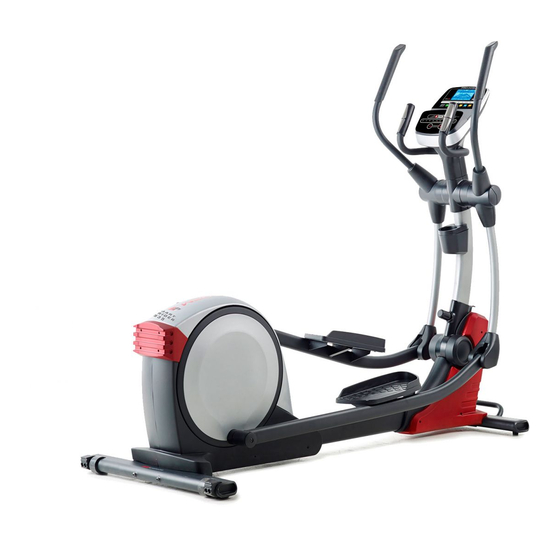
Model No. PFEVEL87914.1
Serial No.
USER'S MANUAL
Write the serial number in the space
above for reference.
Serial Number
Decal
CUSTOMER SERVICE
UNITED KINGDOM
Call: 0330 123 1045
From Ireland: 053 92 36102
Website: www.iconsupport.eu
E-mail: csuk@iconeurope.com
Write:
ICON Health & Fitness, Ltd.
Unit 1D, The Gateway
Fryers Way, Silkwood Park
OSSETT
WF5 9TJ
UNITED KINGDOM
AUSTRALIA
Call: 1800 993 770
E-mail: australiacc@iconfitness.com
Write:
ICON Health & Fitness
PO Box 635
WINSTON HILLS NSW 2153
AUSTRALIA
CAUTION
Read all precautions and
instructions in this manual before
using this equipment. Keep this
manual for future reference.
www.iconeurope.com
Advertisement
Table of Contents

Related Manuals for ProForm 900 ZLE


Summary of Contents for ProForm 900 ZLE
- Page 1 Model No. PFEVEL87914.1 Serial No. USER’S MANUAL Write the serial number in the space above for reference. Serial Number Decal CUSTOMER SERVICE UNITED KINGDOM Call: 0330 123 1045 From Ireland: 053 92 36102 Website: www.iconsupport.eu E-mail: csuk@iconeurope.com Write: ICON Health & Fitness, Ltd. Unit 1D, The Gateway Fryers Way, Silkwood Park OSSETT...
-
Page 2: Table Of Contents
Note: The decal(s) may not be shown at actual size. Google Maps is a trademark of Google Inc. IFIT is a registered trademark of ICON Health & Fitness, Inc. PROFORM is a registered trademark of ICON Health & Fitness, Inc. -
Page 3: Important Precautions
IMPORTANT PRECAUTIONS WARNING: To reduce the risk of serious injury, read all important precautions and instructions in this manual and all warnings on your elliptical before using your elliptical. ICON assumes no responsibility for personal injury or property damage sustained by or through the use of this product. -
Page 4: Before You Begin
Thank you for selecting the revolutionary PROFORM manual. To help us assist you, note the product model ® 900 ZLE elliptical. The 900 ZLE elliptical provides an number and serial number before contacting us. The impressive selection of features designed to make your model number and the location of the serial number workouts at home more effective and enjoyable. -
Page 5: Assembly
ASSEMBLY • Assembly requires two persons. one Phillips screwdriver • Place all parts in a cleared area and remove the one rubber mallet packing materials. Do not dispose of the packing materials until you finish all assembly steps. Assembly may be easier if you have a set of wrenches. -
Page 6: Upright Position
3. If there are shipping supports (not shown) attached to the front of the Frame (1), remove the screws from the shipping supports, and dis- card the screws and the shipping supports. With the help of another person, place some packing inserts from the packing material under the Frame (1) so that the Frame is lifted off the floor. -
Page 7: Upright Position
5. Rotate the Right Upper Body Arm (9) to the upright position. Attach the Right Upper Body Arm (9) to the Right Upper Body Leg (6) with an M10 x 50mm Screw (95). Then, tighten the indicated M10 x 45mm Hex Screw (78). -
Page 8: How To Use The Elliptical
HOW TO USE THE ELLIPTICAL HOW TO PLUG IN THE POWER ADAPTER HOW TO MOVE THE ELLIPTICAL IMPORTANT: If the elliptical has been exposed to Due to the size and weight of the elliptical, moving cold temperatures, allow it to warm to room tem- it requires two persons. - Page 9 HOW TO EXERCISE ON THE ELLIPTICAL Then, lift the handle on the front stabilizer and tip the frame upright until the elliptical rests on the small and To mount the elliptical, hold the handlebars or the large storage feet. upper body arms and step onto the pedal that is in the lower position.
- Page 10 CONSOLE DIAGRAM MAKE YOUR FITNESS GOALS A REALITY WITH IFIT.COM With your new iFit-compatible fitness equipment, you can use an array of features on iFit.com to make your fitness goals a reality: Exercise anywhere in the world with customizable Google Maps. Download training workouts designed to help you reach your personal goals.
- Page 11 FEATURES OF THE CONSOLE HOW TO USE THE MANUAL MODE The advanced console offers an array of features 1. Begin pedaling or press any button on the console to turn on the console. designed to make your workouts more effective and enjoyable.
- Page 12 Calories (Cals.)—This display mode will show the As you exercise, the workout intensity level bar approximate number of calories you have burned. will indicate the approximate intensity level of your exercise. Calories per Hour (Cals./Hr)—This display mode will show the approximate number of calories you are burning per hour.
- Page 13 6. When you are finished exercising, the console When your pulse is detected, a heart symbol will flash in the display each time your heart beats, will turn off automatically. one or two dashes will appear, and then your heart rate will be shown.
- Page 14 HOW TO USE AN ONBOARD WORKOUT At the end of each segment of the workout, a series of tones will sound and the next segment of 1. Begin pedaling or press any button on the the profile will begin to flash. If a different resis- console to turn on the console.
- Page 15 HOW TO USE A SET-A-GOAL WORKOUT Note: The calorie goal is an estimate of the number of calories that you will burn during 1. Begin pedaling or press any button on the the workout. The actual number of calories that console to turn on the console.
- Page 16 HOW TO USE AN IFIT WORKOUT 3. Select a user. You must have an iFit module to use an iFit workout. If more than one user is registered on your iFit To purchase an iFit module at any time, go to account, you can switch users in the iFit main www.iFit.com or call the telephone number on the screen.
- Page 17 6. Follow your progress with the display. HOW TO USE THE SOUND SYSTEM See step 4 on page 11. To play music or audio books through the console sound system while you exercise, plug a 3.5 mm male The My Trail tab will show a map of the trail or it will to 3.5 mm male audio cable (not included) into the show a track and the number of laps you complete.
- Page 18 HOW TO CHANGE CONSOLE SETTINGS measurement, press the Enter button repeatedly. To view distance in miles, select ENGLISH. To view 1. Select the settings mode. distance in kilometers, select METRIC. Demo—The console features a display demo To select the settings mode, press and hold the Disp.
-
Page 19: Maintenance And Troubleshooting
MAINTENANCE AND TROUBLESHOOTING MAINTENANCE Next, look into the access opening and locate the Reed Switch (58). Rotate the Pulley (66) until a Regular maintenance is important for optimal Magnet (41) is aligned with the Reed Switch. Note: For performance and to reduce wear. Inspect and properly clarity, the shields are shown removed in the drawing tighten all parts each time the elliptical is used. - Page 20 HOW TO ADJUST THE DRIVE BELT See EXPLODED DRAWING C on page 27. Identify the Left and Right Shields (44, 45). Remove all of the If the pedals slip while you are pedaling, even while the M4 x 16mm Screws (61) and 3/16" x 1 1/2" Screws (64) from the Left and Right Shields.
-
Page 21: Exercise Guidelines
EXERCISE GUIDELINES Burning Fat—To burn fat effectively, you must exer- WARNING: cise at a low intensity level for a sustained period of Before beginning this time. During the first few minutes of exercise, your or any exercise program, consult your physi- body uses carbohydrate calories for energy. - Page 22 SUGGESTED STRETCHES The correct form for several basic stretches is shown at the right. Move slowly as you stretch; never bounce. 1. Toe Touch Stretch Stand with your knees bent slightly and slowly bend forward from your hips. Allow your back and shoulders to relax as you reach down toward your toes as far as possible.
-
Page 23: Part List
PART LIST Model No. PFEVEL87914.1 R0516A Key No. Qty. Description Key No. Qty. Description Frame Stabilizer Cap Upright Right Pedal Arm Rear Upright Cover Wheel Console Small Storage Foot Accessory Tray Idler Right Upper Body Leg Small Spacer Eddy Mechanism Resistance Motor Left Upper Body Arm Handle Cover... - Page 24 Key No. Qty. Description Key No. Qty. Description M10 x 50mm Screw M8 x 20mm Hex Bolt Pivot Screw Power Adapter Idler Screw Receiver M6 Washer Extension Wire M8 Locknut Crank Spacer Power Wire – User’s Manual Left Upper Body Leg –...
-
Page 25: Exploded Drawing
EXPLODED DRAWING A Model No. PFEVEL87914.1 R0516A... - Page 26 EXPLODED DRAWING B Model No. PFEVEL87914.1 R0516A...
- Page 27 EXPLODED DRAWING C Model No. PFEVEL87914.1 R0516A...
-
Page 28: Ordering Replacement Parts
ORDERING REPLACEMENT PARTS To order replacement parts, see the front cover of this manual. To help us assist you, please be prepared to provide the following information when contacting us: • the model number and serial number of the product (see the front cover of this manual) •...