
Related Manuals for Motorola nvg589


Summary of Contents for Motorola nvg589
- Page 1 Administrator’s Handbook Motorola ® Embedded Software Version 9.1.0 Motorola ® NVG589 VDSL2 Gateway...
- Page 2 (such as translation, transformation, or adaptation) without written permission from Motorola Mobility LLC Motorola reserves the right to revise this publication and to make changes in content from time to time without obligation on the part of Motorola to provide notification of such revision or change. Motorola pro- vides this guide without warranty of any kind, implied or expressed, including, but not limited to, the implied warranties of merchantability and fitness for a particular pur-...
-
Page 3: Table Of Contents
Cradle Installation Instructions ......19 Set up the Motorola Gateway ......20 Accessing the Web Management Interface . - Page 4 Administrator’s Handbook Wireless Scan ........51 Subnets &...
- Page 5 Var rädd om miljön genom återvinning......181 Copyright Acknowledgments ......183 ® Motorola Gateway Captive Portal Implementation 203 Appendix A Overview .
- Page 6 Administrator’s Handbook X_00D09E_SetCaptivePortalParams RPC: ....205 Quality of Service (QoS) Examples ....207 Appendix B Overview .
-
Page 7: Chapter 1 Introduction
Gateway acts as a pass-through device and allows the workstations on your LAN to have public addresses directly on the Internet. Motorola, Inc. provides a suite of technical information for its family of intelligent enterprise and consumer Gate- ways. It consists of: ◆... -
Page 8: Documentation Conventions
Denotes an area of emphasis on a Web page solid rounded rectangle with an arrow Command Line Interface Syntax conventions for the Motorola Gateway command line interface are as follows: Convention Description straight ([ ]) brackets in cmd line Optional command arguments... -
Page 9: Organization
It gives a table of conventions. ◆ ® Chapter 2, “Device Configuration” — Describes how to get up and running with your Motorola Gateway. ◆ Chapter 3, “Basic Troubleshooting” — Gives some simple suggestions for troubleshooting problems with your Gateway’s initial configuration. - Page 10 Administrator’s Handbook...
-
Page 11: Chapter 2 Device Configuration
Most users will find that the basic Quick Start configuration is all that they ever need to use. The Quick Start sec- ® tion may be all that you ever need to configure and use your Motorola Gateway. For more advanced users, a rich feature set is available. -
Page 12: Important Safety Instructions
POWER SUPPLY INSTALLATION ® Connect the power supply cord to the power jack on the Motorola Gateway. Plug the power supply into an appro- priate electrical outlet. There is no power (on / off) switch to power off the device. -
Page 13: Motorola ® Gateway Status Indicator Lights
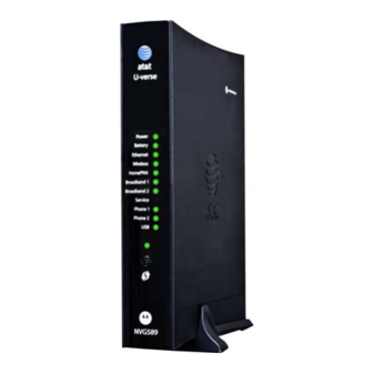
® Motorola Gateway Status Indicator Lights ® Colored LEDs on your Motorola Gateway indicate the status of various port activity. Motorola® Gateway NVG589 status indicator lights Side View Power Battery Ethernet Wireless HomePNA Broadband 1 Broadband 2 Service Phone 1... - Page 14 Administrator’s Handbook Action Solid Green = Powered device connected to the associated port (includes devices with wake-on-LAN capability where a slight voltage is supplied to the Ethernet connection). Flickering Green = Activity seen from devices associated with the port. The flickering of the Ethernet light is synchronized to actual data traffic.
- Page 15 ☛ NOTE: The NVG589 supports two VoIP lines over one RJ11 VoIP port. In order to connect two phone lines the supplied inner/outer pair splitter adapters must be attached to the RJ11 VoIP port in order to terminate both lines.
-
Page 16: Battery Installation (Optional)
The battery used in this device may present a risk of fire or chemical burn if mis- treated. Do not disassemble, heat above manufacturer’s maximum temperature limit, or incinerate. Replace battery with Motorola P/N 586185-001-00 only. Use of another battery may present a risk of fire or explosion. -
Page 17: Battery Door Installation Instructions
Battery Door Installation Instructions Place NVG589 Unit on a table top as shown in FIGURE (1). Place battery door at an angle, as shown, and slide toward edge of unit. See FIGURE (2). Rotate door in direction shown, see FIGURE (3), and snap closed. -
Page 18: Battery Door Removal Instructions
Administrator’s Handbook Battery Door Removal Instructions Place unit on table top as shown in FIGURE (1). Using both hands, pull tabs in directions shown in FIGURE (2). While still pulling the tabs, pull the battery door in the direction shown. See FIGURE (3). -
Page 19: Cradle Installation Instructions
Cradle Installation Instructions Angle the NVG589 unit onto the rear of the cradle. See FIGURE (1). Ensure that the NVG589 unit is latched to the rear of the cradle as shown in FIGURE (2). Once the rear is latched, rotate the NVG589 unit down into the cradle and press until the snap is engaged. -
Page 20: Set Up The Motorola Gateway
Set up the Motorola Gateway ® Refer to your Quickstart Guide for instructions on how to connect your Motorola gateway to your power source, PC or local area network, and your Internet access point, whether it is a dedicated DSL outlet or a DSL or cable ®... - Page 21 . Windows Vista and Windows 7 obtain an IP address automatically by default. You may not need to configure it at all. To check, open the Networking Control Panel and select Internet Protocol Version 4 (TCP/IPv4). Click the Properties button. The Internet Protocol Version 4 (TCP/IPv4) Properties window should appear as shown.
- Page 22 Administrator’s Handbook Macintosh MacOS 8 or higher or Mac OS X: Step 1. Access the TCP/IP or Network control panel. . MacOS follows a path like this: Apple Control Panels TCP/IP Menu -> -> Control Panel . Mac OS X follows a path like this: Apple System Preferences Network...
-
Page 23: Accessing The Web Management Interface
Accessing the Web Management Interface Run your Web browser application, such as Firefox or Microsoft Internet Explorer, ® from the computer connected to the Motorola Gateway. Enter http://192.168.1.254 in the Location text box. While the Gateway is determining the Broadband network type, the following screen appears. - Page 24 Administrator’s Handbook Check to make sure the Broadband and Service LEDs are lit GREEN to verify that the connection to the Internet is active. Congratulations! Your installation is complete. You can now surf to your favorite Web sites by typing an URL in your browser’s location box or by selecting one of your favorite Internet bookmarks.
-
Page 25: Broadband Network Redirect Pages
Broadband Network Redirect Pages After a few minutes if the Broadband network cannot be determined, the following screen appears. Contact AT&T Customer care at the number shown for assistance. Continue If you click the button, the following screen appears. Here you can manually select the Broadband net- work type, if you know it. -
Page 26: Ip Diagnostics Page Redirect
Administrator’s Handbook IP Diagnostics Page Redirect In the event that your connection to the Internet fails, the Broadband LED will flash and you are redirected to the IP Diagnostics page. Follow the on-screen troubleshooting suggestions. For additional troubleshooting information, see “Diagnostics”... -
Page 27: Device Status Page
Device Status page ® After you have performed the basic Easy Login configuration, any time you log in to your Motorola Gateway you ® will access the Motorola Gateway Home Page. http://192.168.1.254 You access the Home Page by typing in your Web browser’s location box. - Page 28 Administrator’s Handbook The Device Status Page appears.
- Page 29 The Device Status displays the following information in the center section: Field Description Broadband Broadband Connection ‘Waiting for DSL’ is displayed while the Gateway is training. This should change to ‘Up’ within two minutes. ‘Up’ is displayed when the ADSL line is synched and the session is established.
- Page 30 Administrator’s Handbook ◆ Find a computer on your home network » This link will connect you to the Device List page. See “Device List” on page ◆ Adjust firewall settings for gaming and applications » This link will connect you to the NAT/Gaming page. See “NAT/Gaming”...
-
Page 31: Tab Bar
Tab Bar The tab bar is located at the top of every page, allowing you to move freely about the site. The tabs reveal a succession of pages that allow you to manage or configure several features of your Gateway. Each tab is described in its own section. -
Page 32: Links Bar
Administrator’s Handbook Links Bar The links bar at the top of each page allows you to configure different aspects of the features displayed on the page. For example, on the Home Summary page, the button bar is shown below: Click the links below to be taken to each section. ◆... - Page 33 For Wireless client connections, the Device List displays the familiar bars indicating signal strength, as follows: ◆ Clear Device List Click the button to update the Home Network summary. ◆ Scan for Devices Click the button to seek out other devices that have been connected since the last Home Network summary update.
-
Page 34: System Information
Administrator’s Handbook Link: System Information System Information When you click the link, the System Information page appears. The page displays the following information: System Information Manufacturer This is the manufacturer’s identifier name. Model Number This is the manufacturer’s model number. Serial Number This is the unique serial number of your Gateway. -
Page 35: Access Code
Link: Access Code Access to your Gateway is controlled through an account named Admin. The default Admin password for your Gateway is the unique Access Code printed on the label on the side of your Gateway. As the Admin, you can change this password to a different one of your own choosing between 8 and 20 characters long. -
Page 36: Restart Device
Administrator’s Handbook Link: Restart Device When the Gateway is restarted, it will disconnect all users, initialize all its interfaces, and load the Operating Sys- tem Software. When you make configuration changes, you may be required restart for the changes to take effect. -
Page 37: Broadband
Broadband Broadband When you click the tab, the Broadband Status page appears. The Broadband Status page displays information about the Gateway’s WAN connection(s) to the Internet. Broadband Status Line State May be Up (connected) or Down (disconnected). Broadband Connection May be Up (connected) or Down (disconnected). - Page 38 Administrator’s Handbook Downstream Sync Rate This is the rate at which your connection can download (receive) data on your DSL line, in kilobits per second. Upstream Sync Rate This is the rate at which your connection can upload (send) data on your DSL line, in kilobits per second.
-
Page 39: Configure
Link: Configure Configure When you click the link, the Broadband Configure screen appears. Here you can reconfigure your type of broaband connection should it change in the future. ◆ Broadband Connection Source - dsl, ethernet, or auto (automatically detected). ◆ Media –... -
Page 40: Igmp Stats
Administrator’s Handbook Link: IGMP Stats IGMP Stats When you click the link, the IGMP Stats screen appears. The IGMP Statistics screen reports IGMP Proxy Groups and Multicast Forwarding information. It also displays a packet counter. -
Page 41: Home Network
Home Network Home Network When you click the tab, the Home Network Status page appears. The Home Network Status page displays informa- tion about the Gateway’s local area network. Run Congestion Detection If you click the but- ton, the device will generate statistics for each of the 11 channels available, displaying: ◆... - Page 42 Administrator’s Handbook Home Network Status Device IPv4 Address The Gateway’s own IP address on the network. DHCP Netmask The Gateway’s own netmask on the network. DHCPv4 Start Address The starting IP address of the DHCP range served by the Gateway. DHCPv4 End Address The ending IP address of the DHCP range served by the Gateway.
- Page 43 Wireless MAC Address Shows the information of the MAC address of the wireless subsystem. LAN Wireless Statistics Transmit Bytes Number of bytes transmitted on the Wi-Fi network. Receive Bytes Number of bytes received on the Wi-Fi network. Transmit Packets Number of packets transmitted on the Wi-Fi network. Receive Packets Number of packets received on the Wi-Fi network.
-
Page 44: Configure
Administrator’s Handbook Link: Configure Configure When you click the link, the Configure page for the Ethernet LAN appears. For each Ethernet Port, 1 through 4, you can select: ◆ Ethernet – Auto (the default self-sensing rate), 10M full- or half-duplex, 100M full- or half-duplex, or 1G full- or half-duplex. -
Page 45: Hpna Configure
Link: HPNA Configure HPNA Configure When you click the link, the HPNA Configure page for the HomePNA network appears. Here you can turn HomePNA Networking On or Off. If desired, you can choose the Output Jack, either the Coax jack or the Phone jack, or let the device Auto sense it automatically. -
Page 46: Wireless
Administrator’s Handbook Link: Wireless Wireless When you click the link the Wireless page appears. The Wireless page displays the status of your Wireless LAN elements. The Wireless page’s center section contains a summary of the Wireless Access Point’s configuration settings and operational status. Summary Information Field Status and/or Description... - Page 47 ◆ Network Name (SSID) – preset to a number unique to your unit. You can either leave it as is, or change it by entering a freeform name of up to 32 characters, for example “Hercule’s Wireless LAN”. On client PCs’ soft- ware, this might also be called the Network Name.
-
Page 48: Wireless Security
Administrator’s Handbook Wireless Security By default, Wireless Security is set to WPA-PSK with a pre-defined WPA-Default Key (Wireless Protected Access Pre-Shared Key). Other options are available from the Security pull-down menu: ◆ WEP - Manual: WEP Security is a Privacy option that is based on encryption between the Router and any PCs (“clients”) you have with wireless cards. - Page 49 Key Length: The pull-down menu selects the length of each encryption key. The longer the key, the stronger the encryption and the more difficult it is to break the encryption. Key: You enter a key using hexadecimal digits. For 40/64-bit encryption, you need ten digits; 26 digits for 128-bit WEP.
-
Page 50: Mac Filtering
Administrator’s Handbook Link: MAC Filtering MAC Filtering When you click the link the MAC Filtering page appears. MAC Filtering allows you to specify which client PCs are allowed to join the wireless LAN by unique hardware (MAC) address. ◆ To enable this feature, select Blacklist or Whitelist from the MAC Filtering Type menu. Blacklist means that only MAC addresses you specify will be denied access;... -
Page 51: Wireless Scan
Link: Wireless Scan Your device automatically checks for the best channel to broadcast wireless services. However, in some cases it may be useful to switch to a different channel (1 through 11, for North America) on which the network will broad- cast. -
Page 52: Subnets & Dhcp
Administrator’s Handbook Link: Subnets & DHCP Subnets & DHCP When you click the link, the Subnets & DHCP page appears. The Server configuration determines the functionality of your DHCP Settings. This functionality enables the Gate- way to assign your LAN computer(s) a “private” IP address and other parameters that allow network communica- tion. - Page 53 ◆ Primary DHCP Pool: Choose the source of the DHCP pool IP address assignment by selecting either the Pri- vate (local to your LAN) or Public (assigned remotely) radio button. Cascaded Router ◆ Cascaded Router Enable: If you have another router behind this Gateway, choose On from the pull-down menu.
-
Page 54: Hpna
Administrator’s Handbook Link: HPNA HPNA When you click the link, the HPNA Network page appears. The HPNA Network page displays information about the Gateway’s HPNA-connected devices in 15 minute inter- vals. ◆ Set DVR If you have two or more stations, you can select the radio button and click the button to store the MAC address of the station as the “master DVR.”... - Page 55 ◆ Run extended Test You can test the performance of each station to station pair by clicking the button. When Run extended Test you click the button, the following page appears as a warning about this invasive test. If you do not run the Extended Test, the station-to-station performance section is not displayed. ◆...
-
Page 56: Voice
Administrator’s Handbook Voice Voice If you click the ink, the Voice page appears. Voice-over-IP (VoIP) refers to the ability to make voice telephone calls over the Internet. This differs from tradi- tional phone calls that use the Public Switched Telephone Network (PSTN). VoIP calls use an Internet protocol, Session Initiation Protocol (SIP), to transmit sound over a network or the Internet in the form of data packets. -
Page 57: Line Details
Link: Line Details Line Details When you click the link, the Line Details page appears. ◆ Register If your service provider has enabled your VoIP phone lines, you can register them by clicking the Line 1 Register Line 2 button(s). ◆... -
Page 58: Call Statistics
Administrator’s Handbook Link: Call Statistics Call Statistics When you click , the Call Statistics page appears. For Line 1 and Line 2:, the two available phone lines, the Call Statistics page displays the following information: Call Statistics - Line 1 and Line 2 Last Call/Cumulative –... - Page 59 Sum of Inter Arrival Jitter This is calculated continuously in milliseconds as each data packet is received and totalled. Sum of Inter Arrival Jitter This is calculated continuously in milliseconds as each data packet is received Squared and the total is squared. Sum of Franc Loss Fraction Lost: The fraction of RTP data packets lost since the previous SR or RR packet was sent.
- Page 60 Administrator’s Handbook For Line 1 and Line 2:, the two available phone lines, the Call Summary section displays the following informa- tion: Call Summary - Line 1 and Line 2 Current Call/Last Completed Call Call Timestamp Date and Time of the current call Type May be Incoming or Outgoing Duration...
- Page 61 The following table is the simplified version of VOIP line/hook/etc. states during different conditions. VOIP Hook state WAN IP Reg-state Tone Voltage Line 1/2 On/Off-hook Idle Disable On-hook Registered Solid Enabled Off-hook Registered DIAL TONE Blink Enabled On/off hook Failure Enabled On/off hook DOWN...
-
Page 62: Firewall
Administrator’s Handbook Firewall Firewall When you click the tab, the Firewall Status page appears. The Firewall page displays the status of your system firewall elements. All computer operating systems are vulnerable to attack from outside sources, typically at the operating system or Internet Protocol (IP) layers. -
Page 63: Packet Filter
Motorola’s packet filters are designed to provide security for the Internet connections made to and from your net- work. You can customize the Gateway’s filtersets for a variety of packet filtering applications. Typically, you use fil- ters to selectively admit or refuse TCP/IP connections from certain remote networks and specific hosts. - Page 64 Administrator’s Handbook Parts of a filter A filter consists of criteria based on packet attributes. A typical filter can match a packet on any one of the follow- ing attributes: ◆ The source IP address (where the packet was sent from) ◆...
-
Page 65: Working With Packet Filters
Working with Packet Filters To work with filters, begin by accessing the Packet Filter page. Packet Filter ◆ Enable/Disable Packet Filters – Click this button to globally turn your filters on or off. Packet Filter Rules Add a ‘Drop’ Rule Add a ‘Pass’... - Page 66 Administrator’s Handbook ◆ Enter the Source IP Address or Destination IP Address this filter will match on. As you create new Matches, the pulldown items change. There can only be one match from each Match Type for a given rule. Match Types like Source Port, Destination Port, and TCP Flags are only available if other matches (for example, Protocol =TCP) have previously been created.
- Page 67 Packet Filter Rules List Your entries are displayed as a table. ☛ NOTE: Default Forwarding Filter If you create one or more filters that have a matching action of forward, then action on a packet matching none of the filters is to block any traffic. Therefore, if the behavior you want is to force the routing of a certain type of packet and pass all oth- ers through the normal routing mechanism, you must configure one filter to match the first type of packet and apply Force Routing.
- Page 68 Administrator’s Handbook Pass 207.53.17.0/24 8080 Drop 8080 ☛ Port Warnings: If the packet filter or port forwarding rule involves TCP port 80 or 3389; or UDP port 47806, 43962, 69, 123, or 53; or If you attempt to add or change a match such that this occurs AND if running in VDSL/Ethernet mode, the following warning will appear.
-
Page 69: Nat/Gaming
Link: NAT/Gaming NAT/Gaming When you click the link, the NAT/Gaming page appears. NAT/Gaming allows you to host internet applications when NAT is enabled. You can host different games and software on different PCs. From the Service pull-down menu, you can select any of a large number of predefined games and software. (See “List of Supported Games and Software”... - Page 70 Administrator’s Handbook Each time you enable a software service or game your entry will be added to the list of Service names dis- played on the NAT Configuration page. To remove a game or software from the hosted list, choose the game or software you want to remove and click the Remove button.
-
Page 71: Custom Services
Custom Services Add/Edit Services To configure a Custom Service, click the button. The Custom Services page appears. Enter the following information: ◆ Service Name: A unique identifier for the Custom Service. ◆ Global Port Range: Range of ports on which incoming traffic will be received. ◆... - Page 72 Administrator’s Handbook Each time you enable a custom service your entry will be added to the list of Service names displayed on the Custom Services page. Changes are saved immediately. Delete To remove this Service, click the button. Edit To edit this Service, click the button.
- Page 73 List of Supported Games and Software AIM Talk Act of War - Direct Action Age of Empires II Age of Empires, v.1.0 Age of Empires: The Rise of Age of Mythology Rome, v.1.0 Age of Wonders America's Army Apache Asheron's Call Azureus Baldur's Gate I and II Battlefield 1942...
- Page 74 Administrator’s Handbook Microsoft Golf 1998 Edition, v Microsoft Golf 1999 Edition Microsoft Golf 2001 Edition Midtown Madness, v 1.0 Monster Truck Madness 2, v 2.0 Monster Truck Madness, v 1.0 Motocross Madness 2, v 2.0 Motocross Madness, v 1.0 NNTP Need for Speed 3, Hot Pursuit Need for Speed, Porsche Net2Phone...
-
Page 75: Ip Passthrough
IP Passthrough The IP Passthrough feature allows a single PC on the LAN to have the Motorola Gateway’s public address assigned to it. It also provides PAT (NAPT) via the same public IP address for all other hosts on the private LAN subnet. - Page 76 LAN client PC you want to be the IP Passthrough client. You then manually enter the WAN IP address, Gateway Address, etc. that matches the WAN IP address information of your Motorola Gateway. This mode works the same as the DHCP modes. Unsolicited WAN traffic will get passed to this client. The client is still able to access the Motorola Gateway and other LAN clients on the 192.168.1.x network, etc.
- Page 77 NAT Default Server This feature allows you to: ◆ Direct your Gateway to forward all externally initiated IP traffic (TCP and UDP protocols only) to a default host on the LAN, specified by your entry in the Internal Address field. ◆...
-
Page 78: Firewall Advanced
Administrator’s Handbook Link: Firewall Advanced Firewall Advanced When you click the link the Firewall Advanced screen appears. All computer operating systems are vulnerable to attack from outside sources, typically at the operating system or Internet Protocol (IP) layers. Stateful Inspection firewalls intercept and analyze incoming data packets to deter- mine whether they should be admitted to your private LAN, based on multiple criteria, or blocked. - Page 79 Menu item Function Flood Limit Whether packet flooding should be detected and offending packets be dropped; On or Off. Flood rate limit Specifies the number limit of packets per second before dropping the remainder. Flood burst limit Specifies the number limit of packets in a single burst before dropping the remainder.
-
Page 80: Diagnostics
Administrator’s Handbook Diagnostics Diagnostics When you click the tab, the Troubleshoot page appears. This automated multi-layer test examines the functionality of the Router from the physical connections to the data traffic being sent by users through the Router. Run Full Diagnostics You can run all the tests in order by clicking the button. - Page 81 These tests send a PING from the modem to either the LAN or WAN to verify connectivity. A PING could be either an IP address (163.176.4.32) or Domain Name (www.motorola.com). You enter a web address URL or an IP address in the respective field.
- Page 82 Administrator’s Handbook Result Meaning * SKIPPED: The test was skipped because a test on which it depended failed. * PENDING: The test timed out without producing a result. Try running the test again. * WARNING: The test was unsuccessful. The Service Provider equipment your Modem connects to may not support this test.
-
Page 83: Logs
Note: ® Some browsers, such as Internet Explorer for Windows XP, require that you specify the Motorola device’s URL as a “Trusted site” in “Internet Options: Security”. This is necessary to allow the “download” of the log text file to the PC. - Page 84 Administrator’s Handbook The following is an example log portion saved as a .TXT file:...
-
Page 85: Update
Link: Update Update When you click , the Update page appears. Operating System Software is what makes your Gateway run and occasionally it needs to be updated. Your Cur- rent software version is displayed at the top of the page. To update your software from a file on your PC, you must first download the software from your Service Provider's Support Site to your PC's hard drive. -
Page 86: Resets
, the Resets page appears. ® In some cases, you may need to clear all the configuration settings and start over again to program the Motorola Gateway. You can perform a factory reset to do this. It might also be useful to reset your connection to the Internet without deleting all of your configuration settings. -
Page 87: Event Notifications
Link: Event Notifications Event Notifications When you click , the Event Notifications page appears. ◆ If you check the Broadband Status Notification checkbox, the device will alert users on your network if the connection to the Internet should fail. In that event, troubleshooting suggestions will display. ◆... -
Page 88: Nat Table
Administrator’s Handbook Link: NAT Table NAT Table When you click the link, the NAT Table page appears. The NAT Table page displays the network address translation sessions in use by the Gateway. You can use the pull-down menu to limit the displayed sessions to selected IP addresses. Reset To refresh all the sessions displayed, click the button. -
Page 89: Chapter 3 Basic Troubleshooting
CHAPTER 3 Basic Troubleshooting This section gives some simple suggestions for troubleshooting problems with your Gateway’s initial configura- tion. Before troubleshooting, make sure you have ◆ read the User Manual; ◆ plugged in all the necessary cables; and ◆ set your PC’s TCP/IP controls to obtain an IP address automatically. -
Page 90: Status Indicator Lights
Administrator’s Handbook Status Indicator Lights The first step in troubleshooting is to check the status indicator lights (LEDs) in the order outlined below. Motorola® Gateway NVG589 status indicator lights Side View Power Battery Ethernet Wireless HomePNA Broadband 1 Broadband 2... - Page 91 Action Solid Green = Powered device connected to the associated port (includes devices with wake-on-LAN capability where a slight voltage is supplied to the Ethernet connection). Flickering Green = Activity seen from devices associated with the port. The flickering of the Ethernet light is synchronized to actual data traffic.
- Page 92 ☛ NOTE: The NVG589 supports two VoIP lines over one RJ11 VoIP port. In order to connect two phone lines the supplied inner/outer pair splitter adapters must be attached to the RJ11 VoIP port in order to terminate both lines.
-
Page 93: Led Function Summary Matrix
LED Function Summary Matrix Solid Green Flashing Flashing Red Off = The unit The device is Green = A POST fail- has no AC powered. Power-On Self- ure (not boota- power. Test (POST) is ble) or device in progress malfunction occurred. - Page 94 Administrator’s Handbook Solid Green Flashing Flashing Flashing Red Off = The Good broad- Green Green & = No DSL sig- device is not band connec- Attempting If the broad- nal on the line. powered. tion (i.e., good broadband con- band connec- This is only DSL Sync).
- Page 95 If a status indicator light does not look correct, look for these possible problems: If LED is Possible problems not Lit ◆ Make sure the power adapter is plugged into the DSL Modem properly. ◆ Power Try a known good wall outlet. ◆...
-
Page 96: Factory Reset Switch
Administrator’s Handbook Factory Reset Switch Lose your Access Code? This section shows how to reset the Motorola® Gateway so that you can access the configuration screens once again. ☛ NOTE: Keep in mind that all of your settings will need to be reconfigured. -
Page 97: Log Event Messages
Log Event Messages Administration Related Log Messages 1. administrative access This log-message is generated whenever the user attempts to access attempted: the router's management interface. 2. administrative access This log-message is generated whenever the user attempts to access authenticated and allowed: the router's management interface and is successfully authenticated and allowed access to the management interface. - Page 98 Administrator’s Handbook DSL Log Messages (most common): 1. WAN: Data link This log message is generated when the DSL link comes up. activated at <Rate> Kbps (rx/ 2.WAN: Data link deactivated This log message is generated when the DSL link goes down. 3.
- Page 99 Access-related Log Messages 11. TCP SYN flood detected: This log-message is generated whenever a SYN packet destined to the router's management interface is dropped because the number of SYN-sent and SYN-receives exceeds one half the number of allow- able connections in the router. 12.
- Page 100 Administrator’s Handbook Firewall Log Messages Detail (AT&T requirement #841) Log Text Why the packet was Reason Enumeration ( C ) Representation logged NM_LOGDROP_CAT_ICMP ICMP ICMP Packet (generic) NM_LOGDROP_CAT_ICMP_TYPE ICMP-TYPE ICMP Type Field NM_LOGDROP_CAT_ICMP_CODE ICMP-CODE ICMP Code Field NM_LOGDROP_CAT_ICMP6 ICMPv6 ICMPv6 (generic) NM_LOGDROP_CAT_POLICY POLICY Policy (generic).
- Page 101 Firewall Log Messages Detail (AT&T requirement #841) Log Text Why the packet was Reason Enumeration ( C ) Representation logged NM_LOGDROP_CAT_FLOW_FLOOD FLOOD Packets rejected because of flood-limiting NM_LOGDROP_CAT_FLOW_PORTSCA PORTSCAN Packets rejected because of Port-scan detection NM_LOGDROP_CAT_FLOW_DOS_OTH OTHER-DoS Packets rejected because of other DoS detection.
- Page 102 Administrator’s Handbook...
-
Page 103: Chapter 4 Command Line Interface
The Motorola Gateway operating software includes a command line interface (CLI) that lets you access your Motorola Gateway over a telnet connection. You can use the command line interface to enter and update the unit’s configuration settings, monitor its performance, and restart it. - Page 104 Administrator’s Handbook CONFIG Commands “Connection commands” on page 121 “Filterset commands” on page 124 “Queue commands” on page 128 “IP Gateway commands” on page 130 “IPv6 Commands” on page 130 “IP DNS commands” on page 138 “IP IGMP commands” on page 139 “NTP commands”...
-
Page 105: Overview
Overview The CLI has two major command modes: SHELL and CONFIG. Summary tables that list the commands are pro- vided below. Details of the entire command set follow in this section. SHELL Commands Command Status and/or Description to send ARP request clear to erase all stored configuration information clear_certificate... - Page 106 Administrator’s Handbook CONFIG Commands Command Verbs Status and/or Description delete Delete configuration list data help Help command option save Save configuration data script Print configuration data Set configuration data validate Validate configuration settings view View configuration data Keywords conn Connection options TCP/IP protocol options Domain Name System options igmp...
-
Page 107: Starting And Ending A Cli Session
< ip_address > You must know the IP address of the Motorola Gateway before you can make a telnet connection to it. By default, your Motorola Gateway uses 192.168.1.254 as the IP address for its LAN interface. You can use a Web browser to configure the Motorola Gateway IP address. -
Page 108: About Shell Commands
Issue administrative commands to restart Motorola Gateway functions SHELL Prompt When you are in SHELL mode, the CLI prompt is the name of the Motorola Gateway followed by a right angle bracket (>). For example, if you open a CLI connection to the Motorola Gateway named “Motorola-3000/ Motorola-3000/9437188>... -
Page 109: Shell Commands
IP address to an Ethernet hardware address. clear [ yes ] Clears the configuration settings in a Motorola Gateway. You are prompted to confirm the clear command by entering yes. clear_certificate Removes an SSL certificate that has been installed. - Page 110 IP address, in dotted decimal notation, of the device for which you want ip_address DNS information. ping [-s size] [-c count ] [ hostname | ip_address ] Causes the Motorola Gateway to issue a series of ICMP Echo requests for the device with the specified name or IP address. ◆ hostname argument is the name of the device you want to ping;...
-
Page 111: Reset Arp
Clears the Address Resolution Protocol (ARP) cache on your unit. reset crash Clears crash-dump information, which identifies the contents of the Motorola Gateway registers at the point of sys- tem malfunction. reset dhcp server Clears the DHCP lease table in the Motorola Gateway. -
Page 112: Show Config
Displays LAN devices that conform with the TR111 Gateway requirement. It displays - IP Address, Manufacture OUI and Serial number. show enet [ all ] Displays Ethernet interface statistics maintained by the Motorola Gateway. Supports display of individual LAN switch port statistics as well as WAN Ethernet statistics (where applicable). -
Page 113: Show Ip Arp
“IP IGMP commands” on page 139 for detailed explanation. show ip arp Displays the Ethernet address resolution table stored in your Motorola Gateway. show ip igmp Displays the contents of the IGMP Group Address table and the IGMP Report table maintained by your Motorola Gateway. -
Page 114: Show Ip Routes
Display DHCPv6 server lease table. show ipv6 statistics Display IPv6 statistics information. show log Displays blocks of information from the Motorola Gateway diagnostic log. To see the entire log, you can repeat the show log command or you can enter show log all. -
Page 115: Show Pppoe
Displays the current status of a Motorola Gateway, the device's hardware and software revision levels, a summary of errors encountered, and the length of time the Motorola Gateway has been running since it was last restarted. status Identical to the command. -
Page 116: Wan Commands
Use the segment argument to ping a neighbor switch. Use the end-to-end argument to ping a remote end node. reset dhcp client release [ vcc-id ] Releases the DHCP lease the Motorola Gateway is currently using to acquire the IP settings for the specified DSL vcc-id port. The identifier is an “index”... - Page 117 [ vcc-id ] Renews the DHCP lease the Motorola Gateway is currently using to acquire the IP settings for the specified DSL vcc-id port. The identifier is an “index” letter in the range B-I, and does not directly map to the VCC in use.
-
Page 118: About Config Commands
CONFIG Mode Prompt When you are in CONFIG mode, the CLI prompt consists of the name of the Motorola Gateway followed by your current node in the hierarchy and two right angle brackets (>>). For example, when you enter CONFIG mode (by config... -
Page 119: Guidelines: Config Commands
Step Mode: A CLI Configuration Technique The Motorola Gateway command line interface includes a step mode to automate the process of entering configu- ration settings. When you use the CONFIG step mode, the command line interface prompts you for all required and optional information. -
Page 120: Validating Your Configuration
Motorola-3000/9437188 (top)>> validate Error: Subnet mask is incorrect Global Validation did not pass inspection! validate You can use the command to verify your configuration settings at any time. Your Motorola Gateway automatically validates your configuration any time you save a modified configuration. -
Page 121: Config Commands
CONFIG Commands This section describes the keywords and arguments for the various CONFIG commands. Connection commands conns are used to create connections, for example, a WAN or LAN conn. There may be more than one of each depending on your model. names correspond to the system object IDs (OIDs) but you can name them yourself. set conn name name link-oid value Sets the connection named name to point to an associated link specified by the link-oid value. - Page 122 Administrator’s Handbook set conn name name icmp-echo-drop [ off | on ] If set to on, drops echo-requests received on the particular interface. The default is off. set conn name name icmp-err-suppress [ off | on ] An additional option to suppress ICMP error messages on WAN IP interfaces. The default is off. set conn name name static ipaddr ipaddr Specifies a static IP address when the connection type has been set to static.
- Page 123 If dhcp-server-enable is set to on, specifies the first address in the DHCP address range. The Motorola Gateway can reserve a sequence of up to 253 IP addresses within a subnet, beginning with the specified address for dynamic assignment.
-
Page 124: Filterset Commands
[ on | off ] Specifies whether you want the Motorola Gateway to use network address translation (NAT) when communicating with remote Gateways. NAT lets you conceal details of your network from remote Gateways. It also permits all LAN devices to share a single IP address. - Page 125 set filterset name filterset_name rule number order number Determines order of execution of filterset rules (1 before 2, etc). If order is unspecified, the value of order is set to 1 more than the last order in the filterset. If order is set to an already existing order value, order values of other rules are incremented automatically.
- Page 126 Administrator’s Handbook set filterset name filterset_name rule number match-dscp [ number | diffserv_class_string ] Matches diffserv class with supplied numerical value, which can be in decimal(ex: 32) or in Hex(ex: 0x20); Or match the supplied diffserv class. This value may be any of the BE, EF, AFxx or CSx classes. A full list is: { "CS0", 0x00 } { "CS1", 0x08 } { "CS2", 0x10 }...
- Page 127 set filterset name filterset_name rule number action set-qos-marker qos_marker_string Tags the packet according to the queue marker name. See “Queue commands” on page 128 set filterset name filterset_name rule number action set-tos number Sets the packet tos field to the supplied value. set filterset name filterset_name rule number action set-dscp [ number | diffserv_class_string ] Sets the dscp field to the supplied value.
-
Page 128: Queue Commands
Administrator’s Handbook Queue commands Queue configuration typically requires a classification component to set a QoS marker to a packet and a queueing “Filterset com- component to schedule the marked packets to the link. This is accomplished using filtersets ( mands” on page 124 The basic queue's size and “length”... - Page 129 set queue name queue_name bytes [ 2048... 131072 ] Sets the maximum total number of bytes that can be enqueued. set queue name queue_name perturb [ 0... 100 ] Sets the interval in seconds for queue algorithm perturbation when queue option is sfq. set queue name queue_name police-rate [ 0...
-
Page 130: Ip Gateway Commands
Administrator’s Handbook supports bandwidth sharing, that is, if other queues are not busy and there is spare bandwidth, then a busy queue is allowed to go up to the peak rate. set queue name queue_name default-entry queue_name Indicates the input queue which is used if there is no match between the packet queue marker and the configured markers in any of the queue's inputs when the queue type is priority or wfq. - Page 131 set ip6 dhcp-server information-only off set ip6 dhcp-server preference 255 set ip6 dhcp-server authoritative on set ip6 dhcp-server rapid-commit on set ip6 dhcp-server unicast off set ip6 dhcp-server leasequery off set ip6 dhcp-server pd-enable on set ip6 dhcp-server default-lease-time 2592000 set ip6 dhcp-server preferred-lifetime 604800 set ip6 dhcp-server T1 302400 set ip6 dhcp-server T2 483840...
- Page 132 Administrator’s Handbook set ip6 conn name name type [ static | autoconf | rd | dp | aiccu ] Type of connection. See below for connection types. set ip6 conn name name mtu octets Specified MTU of connection. set ip6 conn name name side [ lan | wan ] Specified whether the connection is LAN side or WAN side.
- Page 133 set ip6 conn name name 6rd-tunnel use-dhcp-values [ off | on ] If this parameter is on, 6rd-provisioned parameters are obtained via the underlying DHCPv4 client associated with IPv4 connection named ipv4-name. See “draft-ietf-softwire-ipv6-6rd-10” for DHCP format description. ip6 conn (type = rd, 6rd-tunnel use-dhcp-values = off). set ip6 conn name name 6rd-tunnel prefix IPv6_address 6rd domain prefix.
- Page 134 Administrator’s Handbook Delegated Prefix Connections ip6 conn (type = dp, side = lan). A conn of type “delegated prefix” obtains its global prefix information from one or more prefix from another IPv6 conn (typically a WAN conn), if available. In order for a “dp” connection to become fully operational, its underlying link must be up AND the IPv6 connection which delegates the prefix must have created one or more prefixes from which to draw the “dp”...
- Page 135 set ip6 conn name name dhcp-server addr-count value [ 0 - 256 ] The number of IPv6 addresses available to serve to DHCPv6 stateful clients. If the addr-count parameter is set to zero, the DHCPv6 server operates in “stateless” mode. set ip6 conn name name dhcp-server start-addr-offset value [ 0 - 65536 ] If the addr-count parameter is greater than zero, the start address is an offset from the base address of the prefix which is assigned to the LAN conn.
- Page 136 Administrator’s Handbook set ip6 dhcp-server pd-enable [ on | off } Enables or disables prefix delegation globally on all DHCPv6 servers on all IPv6 LAN conns, overriding individual DHCPv6 server settings. The default is on. set ip6 dhcp-server default-lease-time seconds Sets the global DHCPv6 lease time setting in seconds.
- Page 137 set ip6 static-route name prefix IPv6_prefix IPv6 prefix. set ip6 static-route name prefix-length value [ 1 - 64 ] IPv6 prefix-length. set ip6 static-route name metric value [ 0 - 255 ] metric assigned to route.
-
Page 138: Ip Dns Commands
Administrator’s Handbook IP DNS commands set ip dns domain-name domain_name Specifies the default domain name for your network. When an application needs to resolve a host name, it appends the default domain name to the host name and asks the DNS server if it has an address for the “fully qualified host name.”... -
Page 139: Ip Igmp Commands
Other uses include updating the address books of mobile computer users in the field, or sending out company newsletters to a distribution list. Since a router should not be used as a passive forwarding device, Motorola Gateways use a protocol for forward- ing multicasting: Internet Group Management Protocol (IGMP). - Page 140 Administrator’s Handbook tion Profile. ◆ Last Member Query Interval – the amount of time in tenths of a second that the IGMP gateway waits to receive a response to a Group-Specific Query message. The last member query interval is also the amount of time in seconds between successive Group-Specific Query messages.
-
Page 141: Ntp Commands
set ip igmp last-member-interval value Sets the last member query interval: the amount of time in tenths of a second that the IGMP gateway waits to receive a response to a Group-Specific Query message. The last member query interval is also the amount of time in seconds between successive Group-Specific Query messages. -
Page 142: Application Layer Gateway (Alg) Commands
Administrator’s Handbook Application Layer Gateway (ALG) commands These commands allow you to enable or disable the router’s support for a variety of Application Layer Gateways (ALGs). An application layer gateway (ALG) is a NAT component that helps certain application sessions to pass cleanly through NAT. -
Page 143: Link Commands
set ip dynamic-dns service-type [ dyndns ] set ip dynamic-dns username myusername set ip dynamic-dns password mypassword set ip dynamic-dns hostname myhostname set ip dynamic-dns retries [ 1 - 64 ] Enables or disables dynamic DNS services. The default is off. If you specify dyndns.org, you must supply your hostname, username for the service, and password. - Page 144 Administrator’s Handbook set link name name tagged-vlan name integer priority [ 0 - 7 ] Specifies the 802.1p priority bit. If you set this to a value greater than 0, all packets of this VLAN with unmarked priority bits (pbits) will be re-marked to this priority. set link name name supplicant type [ none | eap-tls ] Specifies whether the EAP TLS supplicant is enabled on the link named name.
- Page 145 [ instant-on | always-on ] ® Specifies whether a PPP connection is maintained by the Motorola Gateway when it is unused for extended peri- ods. If you specify always-on , the Gateway never shuts down the PPP link. If you specify instant-on , the Gate- way shuts down the PPP link after the number of seconds specified in the time-out setting (below) if no traffic is moving over the circuit.
-
Page 146: Management Commands
Specifies this particular Access Concentrator unit from all others.. Some access provider networks may have mul- tiple PPPoE servers, and having the Motorola Gateway indicate an AC Name specifies to which one the Motorola Gateway is trying to connect. - Page 147 Specifies the port number for telnet (CLI) communication with the Motorola Gateway. Because port numbers in the range 0-1024 are used by other protocols, you should use numbers in the range 1025-65534 when assigning new port numbers to the Motorola Gateway telnet configuration interface. A setting of 0 (zero) will turn the server off.
-
Page 148: Remote Access Commands
0-1024 are used by other protocols, you should use numbers in the range 1025-65534 when assigning new port numbers to the Motorola Gateway telnet configuration interface. A setting of 0 (zero) will turn the server off. Defaults to port 0. - Page 149 Specifies the maximum number of client sessions for remote telnet access management. Defaults to 4. set management remote-access ssh-port [ 1 - 65534 ] Specifies the port number for secure shell (SSH) communication with the Motorola Gateway. Defaults to port 22. set management remote-access ssh-idle-timeout [ 1...120 ] Specifies a timeout period of inactivity for remote secure shell (SSH) access to the Gateway, after which a user must re-login to the Gateway.
-
Page 150: Physical Interfaces Commands
Administrator’s Handbook Physical interfaces commands DSL interfaces set physical dsl enable [ off | on ] Turns the physical DSL interface off or on. Default is on. set physical dsl dsl-mode [ auto | single | bonded ] Sets the mode for the DSL connection, whether a single line or bonded. If the default auto is set, the device will try both single and bonded, attempting to detect and lock on the mode in use. - Page 151 set physical dsl profile-8c [ on | off ] Enables or disables VDSL2 profile 8c governing upstream and downstream bandwidth. Default is on. set physical dsl profile-8d [ on | off ] Enables or disables VDSL2 profile 8d governing upstream and downstream bandwidth. Default is on. set physical dsl profile-12a [ on | off ] Enables or disables VDSL2 profile 12a governing upstream and downstream bandwidth.
- Page 152 Administrator’s Handbook set physical dsl atm vcc 1 aal-type [ aal5 | aal0pkt | aal0cell ] Sets the ATM Adaptation Layer type (aal-type): AAL5, AAL0-packet, or AAL0-cell. Default is aal5. set physical dsl atm vcc 1 datapath [ phy0fast | phy0interleaved ] Sets the ATM datapath, Fast Path or Interleaved.
- Page 153 set physical dsl ptm datapath [ phy0fast | phy0interleaved ] Sets the ATM datapath, Fast Path or Interleaved. Default is phy0fast. set physical dsl ptm priority [ low | high ] Sets the Packet Transfer Mode (ptm) priority. Default is low. set physical dsl ptm tx-queue queue_name Attaches the egress queue template to the ptm interface when the queue type is egress.
- Page 154 Administrator’s Handbook set physical enet [ 1 - 4 ] rx-queue queue_name Attaches the ingress queue to the ethernet interface when the queue type is ingress. set physical enet [ 1 - 4 ] port power-save enable "" Turns power saving mode off or on. set physical ensw max-age seconds Sets the maximum delay on the Ethernet switch in seconds.
- Page 155 set physical wireless default-channel [ 1... 11 ] (1 through 11, for North America) on which the network will broadcast. This is a frequency range within the 2.4Ghz band. Channel selection depends on government regulated radio frequencies that vary from region to region. The widest range available is from 1 to 14.
-
Page 156: Pppoe Relay Commands
Administrator’s Handbook set physical wireless ssid 3 enable [ off | on ] Enables or disables the third available SSID. set physical wireless ssid 4 enable [ off | on ] Enables or disables the fourth available SSID. set physical wireless wps [ on | off ] Enables or disables Wi-Fi Protected Setup (WPS) for simplified security configuration with Wi-Fi clients that sup- port it. -
Page 157: Nat Pinhole Commands
NAT Pinhole commands NAT pinholes let you pass specific types of network traffic through the NAT interfaces on the Motorola Gateway. NAT pinholes allow you to route selected types of network traffic, such as FTP requests or HTTP (Web) connec- tions, to a specific host behind the Motorola Gateway transparently. - Page 158 Administrator’s Handbook set security spi unknown-ethertypes-drop [ on | off ] Enables or disables whether packets with unknown ether types are to be dropped. Default is on. set security spi portscan-protect [ on | off ] Enables or disables whether to detect and drop port scans. Default is on. set security spi invalid-tcp-flags-drop [ on | off ] Enables or disables whether packets with invalid TCP flag settings (NULL, FIN, Xmas, etc.) are to be dropped.
-
Page 159: Voip Commands
Motorola 9.x DSL Gateways use the relevant session information about whether the packet flow was initiated from the LAN side (upstream) or WAN side (downstream). If the parameter security.spi.ip6.allow-inbound is set to off, then sessions which are initiated from the WAN side are disallowed. - Page 160 Administrator’s Handbook set voip phone n sip-registrar-server [ server_name | ip_address ] Specifies the SIP registration server for the specified phone by fully qualified server name or IP address. set voip phone n sip-registrar-server-port [ 1 - 65535 ] Specifies the SIP registration server port number for the specified phone. Default is 5060. set voip phone n sip-registrar-server-transport [ udp | tcp ] Specifies the SIP registration server transport protocol for the specified phone.
- Page 161 set voip phone n codec G729 priority [ 1 | 2 | 3 | 4 | 5 | 6 | 7 | none ] Assigns a priority to the G729 annex A codec, the common analog voice compression implementation used in North America.
- Page 162 Administrator’s Handbook set voip phone n sip-advanced-setting sip-q-value [ 0 - 10 ] This is used to prioritize the SIP account based on the value. set voip phone n sip-advanced-setting sip-qos-tos-value [ 0 - 255 ] Specifies the SIP Diff-Serv Type of Service (ToS) values for Quality of Service (QoS) assignment. Default is 136. set voip phone n sip-advanced-setting sip-qos-p-bit-value [ 0 - 7 ] Sets a QoS P-bit value for the SIP session.
- Page 163 Codec G711U Codec G711A Codec G729 Codec G726_16 jitter-max-transit-delay jitter-peak-transit-delay jitter-delay-buff-inc jitter-transit-delay-threshold 10000 10000 10000 10000 Codec G726_24 Codec G726_32 Codec G726_40 packetization-time jitter-max-reorder-delay jitter-max-accept-late-seq- jitter-initial-delay jitter-exe-frame-del-mode jitter-max-transit-delay jitter-peak-transit-delay jitter-delay-buff-inc jitter-transit-delay-threshold 10000 10000 10000 Syntax is as follows: set voip advanced-telephony-setting codec codec packetization-time value set voip advanced-telephony-setting codec codec jitter-max-reorder-delay value set voip advanced-telephony-setting codec codec jitter-max-accept-late-seq-num value...
- Page 164 Sets the start and end port values for the RTP port range. Although no ports are specified for the RTP protocol, the RTP data is to be carried on an even UDP port number. The defaults in use for the Motorola Gateway are 8024 and 8036, respectively.
- Page 165 set voip RegionSpecificSettings fxs-debounce-offon-hook-delay seconds Specifies the off/on-hook debounce time delay for removing the ripple signal, in seconds. Default is 300. Call feature settings set voip phone n call-feature call-forwarding-all-option [ off | on ] call-forwarding-all-option – turns unconditional call forwarding on or off. set voip phone n call-feature call-forwarding-on-busy-option [ off | on ] call-forwarding-on-busy-option –...
- Page 166 Administrator’s Handbook set voip phone n dsp-settings echo-max-attenuation [ 0 - 65535 ] echo-max-attenuation – specifies the maximum attenuation level at which to invoke echo cancellation. Default is 16384. set voip phone n dsp-settings echo-tail-length [ 0 - 65535 ] echo-tail-length –...
-
Page 167: System Commands
Motorola-7000/9437188. A system name can be 1 – 255 characters long. Once you have assigned a name to your Motorola Gateway, you can enter that name in the Address text field of your browser to open a connection to your Motorola Gateway. - Page 168 Specifies the password for the update server. The default is "guest". set system calendar-update fwverfile filename Specifies the firmware version filename to the update server. For the AT&T NVG589 the file is "netopiaNVG589_64.txt". set system calendar-update day day_of_month Specifies the numerical day of the month for the update server to be polled, for example, "21".
- Page 169 [ low | medium | high | alerts | failures ] Specifies the types of log messages you want the Motorola Gateway to record. All messages with a level equal to or greater than the level you specify are recorded. For example, if you specify set system diagnostic-level medium, the diagnostic log will retain medium-level informational messages, alerts, and failure messages.
- Page 170 Administrator’s Handbook ◆ low - Low-level informational messages or greater; includes trivial status messages. ◆ medium - Medium-level informational messages or greater; includes status messages that can help monitor network traffic. ◆ high - High-level informational messages or greater; includes status messages that may be significant but do not constitute errors.
-
Page 171: Debug Commands
Debug Commands When you are in SHELL mode, the DEBUG prompt is the name of the Motorola Gateway/DEBUG followed by a right angle bracket (>). For example, if you open a CLI connection to the Motorola Gateway named “Motorola- Motorola-3000/9437188/DEBUG>... - Page 172 Administrator’s Handbook...
-
Page 173: Technical Specifications And Safety Information
1.77 lbs (.80 kg) (with integrated battery) ® Communications interfaces: The Motorola Gateways have a 4-port 10/100/1000Base-T Ethernet switch for your LAN connections, an FXS port for VoIP connections, a HomePNA 3.1 coax port, a USB 2.0 network port, and a 400 mW wireless radio for Wi-Fi connections. -
Page 174: Agency Approvals
Administrator’s Handbook Management/configuration methods: HTTP (Web server), telnet command line interface Diagnostics: Ping, event logging, routing table displays, statistics counters, web-based management, traceroute, nslookup, and diagnostic commands. Agency approvals North America Safety Approvals: ■ United States – UL 60950, Third Edition ■... -
Page 175: Manufacturer's Declaration Of Conformance
Under FCC rules, no customer is authorized to repair this equipment. This restriction applies regardless of whether the equipment is in or out of warranty. Technical Support for Hardware Products 1-877-466-8646 http://www.motorola.com/support ☛ Important This product was tested for FCC compliance under conditions that included the use of shielded cables and connectors between system components. - Page 176 Administrator’s Handbook Before installing this equipment, users should ensure that it is permissible to be connected to the facilities of the local telecommunications company. The equipment must also be installed using an acceptable method of connection. In some cases, the company’s inside wiring associated with a single line individual service may be extended by means of a certified connector assembly (telephone extension cord).
-
Page 177: Important Safety Instructions
Important Safety Instructions Caution DO NOT USE BEFORE READING THE INSTRUCTIONS: Do not connect the Ethernet ports to a carrier or carriage service provider’s telecommunications network or facility unless: a) you have the written consent of the network or facility manager, or b) the connection is in accordance with a connection permit or connection rules. Connection of the Ethernet ports may cause a hazard or damage to the telecommunication network or facility, or persons, with consequential liability for substantial compensation. -
Page 178: 47 Cfr Part 68 Information
This equipment not intended to be repaired by the end user. In case of any problems, please refer to the trouble- shooting section of the Product User Manual before calling Motorola Technical Support. i) Connection to party line service is subject to state tariffs. Contact the state public utility commission, public... -
Page 179: Electrical Safety Advisory
If your home has specially wired alarm equipment connected to the telephone line, ensure the installation of this ® Motorola Series Gateway does not disable your alarm equipment. If you have questions about what will disable alarm equipment, consult your telephone company or qualified installer. -
Page 180: Caring For The Environment By Recycling
Motorola, no lo de las prácticas vigentes en su región. Si no existen sistemas de recolección deseche junto con residuos resi- disponibles, solicite asistencia llamando el Servicio al Cliente de Motorola. denciales o comerciales. Recyclage de votre équipement Motorola Recyclage pour le Veuillez ne pas jeter ce produit avec vos ordures ménagères ou vos rebuts... -
Page 181: Milieubewust Recycleren
Jeśli w danym regionie wyrzucać do komunalnych pojem- nie istnieją systemy zbierania odpadów elektrycznych i elektronicznych, infor- ników na śmieci. macje o utylizacji należy uzyskać od biura obsługi klienta firmy Motorola (Motorola Customer Service). Reciclagem do seu equipamento Motorola Cuidando do meio Não descarte este produto junto com o lixo residencial ou comercial. - Page 182 Administrator’s Handbook Please visit http://www.motorola.com/recycle for instructions on recycling.
-
Page 183: Copyright Acknowledgments
Open Source Software Information For instructions on how to obtain a copy of any source code being made publicly available by Motorola related to software used in this Motorola product you may send your request in writing to: Motorola, Inc. - Page 184 Administrator’s Handbook ===== Copyright (c) 1995 Tatu Ylonen <ylo@cs.hut.fi>, Espoo, Finland All rights reserved “As far as I am concerned, the code I have written for this software can be used freely for any purpose. Any derived versions of this software must be clearly marked as such, and if the derived work is incompatible with the protocol description in the RFC file, it must be called by a name other than “ssh”...
- Page 185 TORT OR OTHERWISE, ARISING FROM, OUT OF OR IN CONNECTION WITH THE SOFTWARE OR THE USE OR OTHER DEALINGS IN THE SOFTWARE. GNU General Public License 2.0 (GPL) This Motorola product contains the following open source software packages licensed under the terms of the GPL 2.0 license: * Linux 2.6.30 * Arptables 0.0.3-4...
- Page 186 Administrator’s Handbook this service if you wish), that you receive source code or can get it if you want it, that you can change the software or use pieces of it in new free programs; and that you know you can do these things. To protect your rights, we need to make restrictions that forbid anyone to deny you these rights or to ask you to surrender the rights.
- Page 187 announcement including an appropriate copyright notice and a notice that there is no warranty (or else, saying that you provide a warranty) and that users may redistribute the program under these conditions, and telling the user how to view a copy of this License.
- Page 188 Administrator’s Handbook 6. Each time you redistribute the Program (or any work based on the Program), the recipient automatically receives a license from the original licensor to copy, distribute or modify the Program subject to these terms and conditions. You may not impose any further restrictions on the recipients’...
- Page 189 POSSIBILITY OF SUCH DAMAGES. END OF TERMS AND CONDITIONS GNU Lesser General Public License 2.1 (LGPL) This Motorola product contains the following open source software packages licensed under the terms of the LGPL 2.1 license: * uClibc 0.9.29 Version 2.1, February 1999 Copyright (C) 1991, 1999 Free Software Foundation, Inc.
- Page 190 Administrator’s Handbook TERMS AND CONDITIONS FOR COPYING, DISTRIBUTION AND MODIFICATION 0. This License Agreement applies to any software library or other program which contains a notice placed by the copyright holder or other authorized party saying it may be distributed under the terms of this Lesser General Public License (also called “this License”).
- Page 191 terms of Section 6. Any executables containing that work also fall under Section 6, whether or not they are linked directly with the Library itself. 6. As an exception to the Sections above, you may also combine or link a “work that uses the Library” with the Library to produce a work containing portions of the Library, and distribute that work under terms of your choice, provided that the terms permit modification of the work for the customer’s own use and reverse engineering for debugging such modifications.
- Page 192 Administrator’s Handbook Each version is given a distinguishing version number. If the Library specifies a version number of this License which applies to it and “any later version”, you have the option of following the terms and conditions either of that version or of any later version published by the Free Software Foundation.
- Page 193 All rights reserved. Redistribution and use in source and binary forms, with or without modification, are permitted provided that the following conditions are met: * Redistributions of source code must retain the above copyright notice, this list of conditions and the following disclaimer. * Redistributions in binary form must reproduce the above copyright notice, this list of conditions and the following disclaimer in the documentation and/or other materials provided with the distribution.
- Page 194 Administrator’s Handbook IMPLIED WARRANTIES OF MERCHANTABILITY AND FITNESS FOR A PARTICULAR PURPOSE ARE DISCLAIMED. IN NO EVENT SHALL THE OpenSSL PROJECT OR ITS CONTRIBUTORS BE LIABLE FOR ANY DIRECT, INDIRECT, INCIDENTAL, SPECIAL, EXEMPLARY, OR CONSEQUENTIAL DAMAGES (INCLUDING, BUT NOT LIMITED TO, PROCUREMENT OF SUBSTITUTE GOODS OR SERVICES; LOSS OF USE, DATA, OR PROFITS;...
- Page 195 * Redistributions in binary form must reproduce the above copyright notice, this list of conditions and the following disclaimer in the documentation and/or other materials provided with the distribution. * Neither the name of the University of Cambridge nor the names of its contributors may be used to endorse or promote products derived from this software without specific prior written permission.
- Page 196 Administrator’s Handbook OUT OF OR IN CONNECTION WITH THE USE OR PERFORMANCE OF THIS SOFTWARE. ------------------------------------------------------------------------------ Author: Arvin Schnell <arvin@suse.de> . (No copyright, but listed the author for attribution.) ------------------------------------------------------------------------------ Copyright (C) 2002 Roaring Penguin Software Inc. This plugin may be distributed according to the terms of the GNU General Public License, version 2 or (at your option) any later version.
- Page 197 [C] The Regents of the University of Michigan and Merit Network, Inc. 1992, 1993, 1994, 1995 All Rights Reserved Permission to use, copy, modify, and distribute this software and its documentation for any purpose and without fee is hereby granted, provided that the above copyright notice and this permission notice appear in all copies of the software and derivative works or modified versions thereof, and that both the copyright notice and this permission and disclaimer...
- Page 198 Administrator’s Handbook IMPLIED WARRANTIES OF MERCHANTABILITY AND FITNESS FOR A PARTICULAR PURPOSE ARE DISCLAIMED. IN NO EVENT SHALL THE REGENTS OR CONTRIBUTORS BE LIABLE FOR ANY DIRECT, INDIRECT, INCIDENTAL, SPECIAL, EXEMPLARY, OR CONSEQUENTIAL DAMAGES (INCLUDING, BUT NOT LIMITED TO, PROCUREMENT OF SUBSTITUTE GOODS OR SERVICES;...
- Page 199 This plugin may be distributed according to the terms of the GNU General Public License, version 2 or (at your option) any later version. ------------------------------------------------------------ Copyright (C) 2000 by Roaring Penguin Software Inc. This program may be distributed according to the terms of the GNU General Public License, version 2 or (at your option) any later version.
- Page 200 Administrator’s Handbook 4. Redistributions of any form whatsoever must retain the following acknowledgment: “This product includes software developed by Tommi Komulainen <Tommi.Komulainen@iki.fi>”. THE AUTHORS OF THIS SOFTWARE DISCLAIM ALL WARRANTIES WITH REGARD TO THIS SOFTWARE, INCLUDING ALL IMPLIED WARRANTIES OF MERCHANTABILITY AND FITNESS, IN NO EVENT SHALL THE AUTHORS BE LIABLE FOR ANY SPECIAL, INDIRECT OR CONSEQUENTIAL DAMAGES OR ANY DAMAGES WHATSOEVER RESULTING FROM LOSS OF USE, DATA OR PROFITS, WHETHER IN...
- Page 201 SPECIAL, INDIRECT OR CONSEQUENTIAL DAMAGES OR ANY DAMAGES WHATSOEVER RESULTING FROM LOSS OF USE, DATA OR PROFITS, WHETHER IN AN ACTION OF CONTRACT, NEGLIGENCE OR OTHER TORTIOUS ACTION, ARISING OUT OF OR IN CONNECTION WITH THE USE OR PERFORMANCE OF THIS SOFTWARE. ----------------------------------------------------------------------- Copyright (C) Andrew Tridgell 1999-2004 Copyright (C) Anton Blanchard 2001...
- Page 202 Administrator’s Handbook claim that you wrote the original software. If you use this software in a product, an acknowledgment in the product documentation would be appreciated but is not required. 2. Altered source versions must be plainly marked as such, and must not be misrepresented as being the original software.
-
Page 203: Appendix A Motorola ® Gateway Captive Portal Implementation
FQDNs will be resolved to IP addresses on BOOT and whenever a new list is pushed. ■ For NVG589, Captive Portal implementation only redirects port 80 traffic.Traffic to port 443 is ■ allowed. DNS Traffic will not be blocked... -
Page 204: Captive Portal Rpc
Administrator’s Handbook Captive Portal RPC RPC supported per 2Wire requirements that will set Captive Portal Parameters. <xs:schema xmlns:xs="http://www.w3.org/2001/XMLSchema" xmlns:soapenv="http://schemas.xmlsoap.org/soap/envelope/" xmlns:soapenc="http://schemas.xmlsoap.org/soap/encoding/" xmlns:tns="urn:dslforum-org:cwmp-1-0" targetNamespace="urn:dslforum-org:cwmp-1-0" elementFormDefault="unqualified" attributeFormDefault="unqualified"> <xs:import namespace="http://schemas.xmlsoap.org/soap/envelope/" schemaLocation="soapenv.xsd"/> <xs:import namespace="http://schemas.xmlsoap.org/soap/encoding/" schemaLocation="soapenc.xsd"/> <xs:complexType name="CaptivePortalParamStruct"> <xs:sequence> <xs:element name="Enable" type="soapenc:boolean"> <xs:annotation> <xs:documentation>If true, the Captive Portal is enabled.< xs:documentation>... -
Page 205: X_00D09E_Setcaptiveportalparams Rpc
</xs:annotation> <xs:complexType/> </xs:element> <!-- X_00D09E_GetCaptivePortalParamsResponse --> <xs:element name="X_00D09E_GetCaptivePortalParamsResponse"> <xs:annotation> <xs:documentation>X_00D09E_GetCaptivePortalParamsResponse response message for X_00D09E_GetCaptivePortalParams request.< xs:documentation> </xs:annotation> <xs:complexType> <xs:sequence> <xs:element name="CaptivePortalParamStruct" type="tns:CaptivePortalParamStruct"/> </xs:sequence> </xs:complexType> </xs:element> X_00D09E_SetCaptivePortalParams RPC: <!-- X_00D09E_SetCaptivePortalParams --> <xs:element name="X_00D09E_SetCaptivePortalParams"> <xs:annotation> <xs:documentation>X_00D09E_SetCaptivePortalParams message to set the Captive Portal parameters on a CPE.</xs:documentation> </xs:annotation>... - Page 206 Administrator’s Handbook...
-
Page 207: Appendix B Quality Of Service (Qos) Examples
Appendix B Quality of Service (QoS) Examples This section contains information about the Motorola Gateway QoS implementation. Overview When packets arrive on a high speed interface and are forwarded to a low speed interface, there is contention for bandwidth. This is the use case for QoS: to make effective use of bandwidth. - Page 208 Administrator’s Handbook Figure 3. Illustration of priority scheduling Figure 4. Illustration of weighted fair queue scheduling Figure 5. Illustration of a hybrid queue that is both priority and WFQ, to both constrain bandwidth usage and expedite one of the queues. After the packet has been classified, it can be put in the proper queue.
-
Page 209: Upstream Qos: Priority And Shaping
Weighted fair queues are used to constrain bandwidth. For example, consider a weighted fair queue with three basic queues as inputs, EF, AF and BE: Input 1: EF Input 2: AF Input 3: BE Each input entry is configured with a weight value, which is the rate at which to limit the traffic. This weight can be either absolute (bps) or a relative percentage of the interface's data-rate. -
Page 210: Downstream Qos: Ethernet Switch
Administrator’s Handbook Packet Rx > Filterset Rules: Match Rule 1? Set QoS marker = EF Match Rule 2? Set QoS marker = AF1 Match Rule 3? Set QoS marker = BE CIR/PIR -> wfq_hi -> PQ1 \ AF4 CIR/PIR \ >... -
Page 211: Index
Index Default Server designing a new filter set Detect Missing Filter Symbols Device Access Code !! command Device List DHCP lease table Diagnostic log Diagnostics Access Code Documentation conventions Address resolution table Downstream QoS Administrator password Arguments, CLI Command Ethernet statistics Event Notifications basic queues Broadband Network Redirect... - Page 212 Administrator’s Handbook Restart Restart command Keywords, CLI Restart Modem LAN Ethernet Statistics Safety Instructions LAN Host Discovery Table Security LEDs filters Link commands Session Initiation Protocol links bar SHELL Command Shortcuts Logging in Commands Logs Prompt SHELL level SHELL mode MAC Filtering show config Management commands...
- Page 213 WiFi-Key Wireless Wireless Security...
- Page 214 Administrator’s Handbook...
- Page 215 ® Motorola Mobility DSL Gateways Motorola Mobility LLC 600 North U.S. Highway 45 Libertyville, Illinois 60048 USA Telephone: +1 847 523 5000 July 13, 2012...
- Page 216 Administrator’s Handbook...