Table of Contents
Advertisement
Advertisement
Table of Contents

Related Manuals for Mitsubishi FX2N-5A


Summary of Contents for Mitsubishi FX2N-5A
- Page 1 USER’S MANUAL -5A Special function block...
- Page 2 • If in doubt about the operation or use of FX -5A Special function block please consult the nearest Mitsubishi Electric distributor. • This manual is subject to change without notice.
- Page 3 FX2N-5A Special function block -5A Special function block Manual number : JY997D11401 USER’S MANUAL Manual revision : A Date : November 2003...
- Page 4 FX2N-5A Special function block...
- Page 5 FX2N-5A Special function block Guidelines for the Safety of the User and Protection of the FX -5A Special function block. This manual provides information for the use of the FX -5A Special function block. The manual has been written to be used by trained and competent personnel. The definition of...
- Page 6 FX2N-5A Special function block Notes on the Symbols Used in this Manual At various times throughout this manual certain symbols will be used to highlight points which are intended to ensure the users personal safety and protect the integrity of equipment.
- Page 7 • All examples and diagrams shown in this manual are intended only as an aid to understanding the text, not to guarantee operation. Mitsubishi Electric will accept no responsibility for actual use of the product based on these illustrative examples.
- Page 8 FX2N-5A Special function block Note Concerning the CE Marking This notification does not guarantee that an entire mechanical module produced in accordance with the contents of the notification comply with the following standards. Compliance to EMC standards of the entire mechanical module should be checked by the user / manufacturer.
- Page 9 Emissions) EN61131-2:1994 Programmable controllers Compliance with all relevant aspects of the standard. /A11:1996 - Equipment requirements (RF Immunity, Fast Transients , ESD and Damped /A12:2000 and tests oscillatory wave) For more details please contact the local Mitsubishi Electric sales site.
- Page 10 FX2N-5A Special function block viii...
-
Page 11: Table Of Contents
FX2N-5A Special function block Contents. Guideline..........................iii 1. Introduction ..................1-1 2. External Dimensions and Parts............2-1 3. Installation ...................3-1 4. Connection to PLC ................4-1 5. Wiring ....................5-1 Caution......................5-1 Input Wiring...................... 5-2 Output Wiring ....................5-3 6. Specifications ..................6-1 Buffer Memory (BFM).................7-1 Buffer Memories (BFM) lists ................ - Page 12 FX2N-5A Special function block Contents. 7.2.12 BFM 21 Writes I/O characteristics (offset/gain Scaling function setting) (READ/WRITE) ....................7-21 7.2.13 BFM 22 Convenient functions setting (READ/WRITE)........7-22 7.2.14 BFM 23 Set parameter for direct control function between input ch and output ch (READ/WRITE) ....................
- Page 13 FX2N-5A Special function block Contents. 8. Adjustment of I/O Characteristics............8-1 Standard I/O characteristics................8-1 Adjustment of I/O characteristics ..............8-8 9. Example program................9-1 Program example for analog input/output............9-1 Outline of FROM/TO commands ..............9-4 Associated Manuals List................A-1...
- Page 14 FX2N-5A Special function block Contents.
-
Page 15: Introduction
FX2N-5A Special function block Introduction 1 Introduction The FX -5A analog special function block has four input channels and one output channel. The input channels receive analog signals and converts them to the comparable digital values. The output channel takes a digital value and outputs an equivalent analog signal. - Page 16 FX2N-5A Special function block Introduction 1 MEMO...
-
Page 17: External Dimensions And Parts
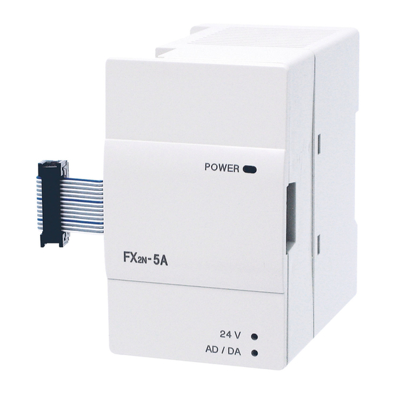
FX2N-5A Special function block External Dimensions and Parts 2 External Dimensions and Parts Dimensions: mm(inches) Terminal 55(2.17") 55(2.17") arrangement 87(3.43") 4(0.16") POWER FX -5A AD/DA 4(0.16") 9(0.35") Mass (Weight): 0.3kg (0.66lbs) - Page 18 FX2N-5A Special function block External Dimensions and Parts 2 1) Direct mounting hole (2-φ4.5) (0.18) 2) Extension cable 3) Power indicator lamp (LED) 5V power is supplied from the programmable controller to light this indicator lamp. 4) Power supply terminals (Screw terminal: M3 (0.12)) 5) Analog output terminals (Screw terminal: M3 (0.12))
-
Page 19: Installation
FX2N-5A Special function block Installation 3 Installation Install the FX -5A to the right side of a main unit, extension unit, extension block or special block of the FX Series PLC. The FX -5A can be installed with DIN rail (DIN46277 of 35 mm in width) or directly installed with screws M4. - Page 20 FX2N-5A Special function block Installation 3 Figure 3.1: Installation with DIN rail • The FX -5A can be installed on DIN rail (DIN46277) of 35 mm in width as it is. For removal, pull down on the DIN rail mounting...
-
Page 21: Connection To Plc
FX2N-5A Special function block Connection to PLC 4 Connection to PLC Connect the FX -5A to the right side of a main unit, extension unit or extension block of FX , FX , FX Series PLC with an extension cable. - Page 22 FX2N-5A Special function block Connection to PLC 4 MEMO...
-
Page 23: Wiring
FX2N-5A Special function block Wiring 5 Wiring Caution 1) Do not lay signal cabling near to high voltage power cabling or house them in the same trunking duct. Effects of noise or surge induction may occur. Keep signal cables at safe dis- tance of more than 100 mm (3.94") from these power cables. -
Page 24: Input Wiring
FX2N-5A Special function block Wiring 5 Input Wiring Figure 5.2: Input Wiring *1 Use a two-core, shielded twisted pair for the analog input line, and separate it +15V from other power lines or a lines easily DC/DC 24V DC induced. -
Page 25: Output Wiring
FX2N-5A Special function block Wiring 5 Output Wiring Please refer to 5.2 for the wiring for "24+", "24-" terminals. Figure 5.3: Output Wiring *1 Use a twisted pair shielded cable for the Voltage output analog output. This cable should be wired... - Page 26 FX2N-5A Special function block Wiring 5 MEMO...
-
Page 27: Specifications
FX2N-5A Special function block Specifications 6 Specifications Table 6.1: General specifications Item Specifications Ambient 0 to +55 °C during operation, -20 to +70 °C during storage temperature range Ambient humidity 35 to 85 % RH during operation (Dew condensation shall not be allowed.) In conformance to JIS C0040 Frequency 10 to 57 Hz, half amplitude 0.075 mm, 57 to 150 Hz, acceleration 9.8... - Page 28 FX2N-5A Special function block Specifications 6 Table 6.2: Power supply specifications Item Specifications Interface driving 24 V DC±10%, 90 mA (maximum), externally supplied power supply CPU driving power 5 V DC, 70 mA, supplied via extension cable from PLC main unit supply Table 6.3: Performance specifications...
- Page 29 FX2N-5A Special function block Specifications 6 Table 6.4: Voltage/current input specifications Item Voltage input Current input -10 to +10 V DC (input resistance: 200 kΩ) Adjustment is enabled with the following conditions: -20 to +20 mA DC, +4 to +20 mA DC Offset value: -32000 to +5000 mV (input resistance: 250 Ω)
- Page 30 FX2N-5A Special function block Specifications 6 Table 6.4: Voltage/current input specifications Item Voltage input Current input • 10 µA (40 mA × 1/4000) -20 to +20 mA at input • 312.5 µV (20 V × 1/64000) • 1.25 µA (40 mA × 1/32000)
- Page 31 FX2N-5A Special function block Specifications 6 Table 6.5: Voltage/current output specifications Item Voltage output Current output -10 to +10 V DC 0 to 20 mA DC, 4 to 20 mA DC (External load resistance:2 kΩ to 1MΩ) (External load resistance:500Ω or less)
- Page 32 FX2N-5A Special function block Specifications 6 MEMO...
-
Page 33: Buffer Memory (Bfm)
FX2N-5A Special function block Buffer Memory (BFM) 7 Buffer Memory (BFM) Caution 1) Do not access the “Reserved” buffer memories “Reserved” (BFM #16, #17, #24, #31 to #40, #46 to #50, #56 to #70, #75 to #80, #85 to #90, #95 to #98, #100, #110, #120 to #199) using FROM/TO instructions. -
Page 34: Buffer Memories (Bfm) Lists
FX2N-5A Special function block Buffer Memory (BFM) 7 Buffer Memories (BFM) lists Table 7.1: BFM Lists Hold against Description Initial value power failure " Specifies input mode of CH1 to CH4. H0000 at shipment " Specifies output mode of CH1. - Page 35 FX2N-5A Special function block Buffer Memory (BFM) 7 Table 7.1: BFM Lists Hold against Description Initial value power failure " #18 Hold last value / reset output to offset value when PLC is stopped Disables setting change of I/O characteristics and convenient functions.
- Page 36 FX2N-5A Special function block Buffer Memory (BFM) 7 Table 7.1: BFM Lists Hold against Description Initial value power failure " #25 Filter mode selection register #26 Upper/lower limit value alarm status (valid while BFM #22 b0 or b1 is ON) A/D data sudden change detection status ...
- Page 37 FX2N-5A Special function block Buffer Memory (BFM) 7 Table 7.1: BFM Lists Hold against Description Initial value power failure • • Reserved • " #51 CH1 gain data (mV, 10µV or mA) K5000 at shipment " #52 CH2 gain data (mV, 10µV or mA) K5000 at shipment "...
- Page 38 FX2N-5A Special function block Buffer Memory (BFM) 7 Table 7.1: BFM Lists Hold against Description Initial value power failure • • Reserved • CH1 lower limit value alarm set value (valid while BFM #22 b0 or b1 "...
- Page 39 FX2N-5A Special function block Buffer Memory (BFM) 7 Table 7.1: BFM Lists Hold against Description Initial value power failure CH4 upper limit value alarm set value (valid while BFM #22 b0 or b1 " K32000 is ON) #85 Reserved ...
- Page 40 FX2N-5A Special function block Buffer Memory (BFM) 7 Table 7.1: BFM Lists Hold against Description Initial value power failure Clear upper and lower limit value alarm and sudden change detection alarm • • Reserved • CH1 average data peak value (minimum value) (valid while BFM #22 ...
- Page 41 FX2N-5A Special function block Buffer Memory (BFM) 7 Table 7.1: BFM Lists Hold against Description Initial value power failure CH1 average data peak value (maximum value) (valid while BFM #111 #22 b2 is ON) CH2 average data peak value (maximum value) (valid while BFM ...
- Page 42 FX2N-5A Special function block Buffer Memory (BFM) 7 Table 7.1: BFM Lists Hold against Description Initial value power failure CH1 Scaling function " #200 K-10200 Analog Value 1 CH1 Scaling function " #201 K-32640 Digital Value 1 CH1 Scaling function "...
- Page 43 FX2N-5A Special function block Buffer Memory (BFM) 7 Table 7.1: BFM Lists Hold against Description Initial value power failure CH2 Scaling function " #219 Digital Value 5 • • • CH4 Scaling function " #238 Analog Value 5 CH4 Scaling function "...
-
Page 44: Details Of Buffer Memories
FX2N-5A Special function block Buffer Memory (BFM) 7 Details of buffer memories 7.2.1 BFM 0 input mode specification (READ/WRITE) BFM 0 specifies the input mode of CH1 to CH4. The BFM consists of a 4-digit hexadecimal code, where one digit is assigned to each input channel. The range for each digit is a Hex value between 0 to F. - Page 45 FX2N-5A Special function block Buffer Memory (BFM) 7 8: Voltmeter display mode (-100mV to + 100mV) (Display range -10000 to +10000) 9: Scaling function (-10 to +10 V) (maximum Display range -32768 to +32767); default = - 32640 to +32640 A:Scaling function Current input mode (-20 to +20 mA) (maximum Display range -32768 to +32767);...
-
Page 46: Bfm 1 Output Mode Specification (Read/Write)
FX2N-5A Special function block Buffer Memory (BFM) 7 7.2.2 BFM 1 output mode specification (READ/WRITE) BFM 1 specifies the output mode of the analog output CH1. The BFM consists of a 4-digit hexadecimal code, where only the lowest digit is assigned to the analog output channel. The range for the digit is a Hex value between 0 to A. - Page 47 FX2N-5A Special function block Buffer Memory (BFM) 7 The output characteristics such as offset and gain settings are automatically changed with the settings of BFM 1. A mode change in BFM 1 will also affect the settings of BFM 45 (offset data) and BFM 55 (gain data) or the settings of BFM 240 to 249 (Scaling function data).
- Page 48 FX2N-5A Special function block Buffer Memory (BFM) 7 7.2.3 BFM 2 to BFM 5 Number of averaging times (READ/WRITE) The number of averaging times of BFM 2 to BFM 5 specify the number of samples that is used to calculate the average values which are displayed in BFM 6 to BFM 9.
-
Page 49: Bfm 6 To Bfm 9 Averaged Input Channel Data (Read Only)
FX2N-5A Special function block Buffer Memory (BFM) 7 7.2.4 BFM 6 to BFM 9 Averaged Input Channel data (READ only) The average A/D conversion data of each input channel is displayed in BFM 6 to BFM 9. The number of samples to calculate the average data is influenced by the setting in BFM 2 to BFM 5) described above. -
Page 50: Bfm 18 Hold/ Reset Analog Output When Plc Is Stopped (Read/Write)
FX2N-5A Special function block Buffer Memory (BFM) 7 7.2.9 BFM 18 hold/ reset analog output when PLC is stopped (READ/WRITE) If BFM 18 is 0, while the PLC base unit is in Stop mode the value of BFM15 (value of BFM14 + direct output function) will be output. -
Page 51: Bmf 19 Setting Change Enable/Disable (Read/Write)
FX2N-5A Special function block Buffer Memory (BFM) 7 7.2.10 BMF 19 setting change enable/disable (READ/WRITE) BFM 19 permits or prohibits the change of the I/O characteristics for the following functions: BFM 0 (input channel mode settings) BFM 1 (output channel mode settings) -
Page 52: Bfm 20 Initialization Function (Reset All Values To Default) (Read/Write)
FX2N-5A Special function block Buffer Memory (BFM) 7 7.2.11 BFM 20 Initialization function (reset all values to default) (READ/WRITE) BFM 20 will reset the FX -5A to the factory default. By initialization, the modes, average numbers, offset/gain settings, direct output control function, lower/upper-limit settings, Scaling function and sudden change function are all reset to factory default (voltage input/output, default offset/gain values). -
Page 53: Bfm 21 Writes I/O Characteristics (Offset/Gain Scaling Function Setting) (Read/Write)
FX2N-5A Special function block Buffer Memory (BFM) 7 7.2.12 BFM 21 Writes I/O characteristics (offset/gain Scaling function setting) (READ/WRITE) The b0 to b4 bits of BFM 21 are assigned to each channel of the FX -5A. (Bit 4 is assingned to the analog output channel, bit 3 is assigned to input channel 4, bit 0 is assigned to input channel 1.) -
Page 54: Bfm 22 Convenient Functions Setting (Read/Write)
FX2N-5A Special function block Buffer Memory (BFM) 7 7.2.13 BFM 22 Convenient functions setting (READ/WRITE) The functions described below are assigned to b0 to b3 of BFM 22. When a bit is set ON, the assigned functions become valid. Other bits, not specified by the values below, will simply be ignored by the module if they are accidentally set by the user. -
Page 55: (Read/Write)
FX2N-5A Special function block Buffer Memory (BFM) 7 b8 to b11: switch off range over/range under alarm for corresponding input channel The value of BFM 22 is stored non-volatile in the internal EEPROM. There is a safety function to protect the internal EEPROM from being destroyed by accidentally writing the same value continuously to BFM 22. -
Page 56: Bfm 24 Reserved
FX2N-5A Special function block Buffer Memory (BFM) 7 BFM#0 H"""" Example: Value in BFM 23 is set to H1234. Output value (BFM 15) = BFM 14(TO) - BFM 10 - BFM 7 + BFM 12 + BFM 9 If at least one Hex digit in BFM 23 is set to a Hex number between 1 and 4, after calculating of the digital output value in BFM 15, the offset/gain setting calculation or the Scaling function calculation is applied to these digital data in order to achieve the real analog output. -
Page 57: Bfm 25 Filter-Level Selection Register (Read/Write)
FX2N-5A Special function block Buffer Memory (BFM) 7 7.2.16 BFM 25 Filter-level selection register (READ/WRITE) The following Table shows the possible values of BFM 25 for using the digital Filter of the -5A-Device: Table 7.2: Bit assignment in BFM 25 Bit No. - Page 58 FX2N-5A Special function block Buffer Memory (BFM) 7 /(sampling time × no. of active channels) [Hz] with Formula for filter cut-off frequency f cut-off frequency factor F =0.1, 0.05, 0.025 or 0.01. There are two filter parameters that can be changed, the filter-level and the cut-off frequency.
- Page 59 FX2N-5A Special function block Buffer Memory (BFM) 7 A/D conversion value when input filter is used. When input filter is used Input filter and when cut-off frequency is used Analog value Analog value Digital value Digital value The change in shorter width than cut-off frequency is disregarded.
-
Page 60: Bfm 26 Upper/Lower Limit Value Alarm Status (Read Only)
FX2N-5A Special function block Buffer Memory (BFM) 7 7.2.17 BFM 26 Upper/lower limit value alarm status (READ only) If the upper/lower limit value detection function (BFM 22 b0, b1) is used, the detection results are written to BFM 26. The lower limit value alarm or the upper limit value alarm of each channel is assigned to each bit of BFM 26. - Page 61 FX2N-5A Special function block Buffer Memory (BFM) 7 Table 7.4: Bit assignment in BFM 26 Bit No. Channel No. Description average data lower limit value alarm average data upper limit value alarm average data lower limit value alarm average data upper limit value alarm...
-
Page 62: Bfm 27 A/D Data Sudden Change Detection Status (Read Only)
FX2N-5A Special function block Buffer Memory (BFM) 7 7.2.18 BFM 27 A/D data sudden change detection status (READ only) When the sudden change detection function is used, the detection result is written to BFM 27. The sudden change detection is activated, if the values in BFM 91 to BFM 94 are bigger than The sudden change detection in + direction or the sudden change detection in - direction of each channel is assigned to each corresponding bit of BFM 27. - Page 63 FX2N-5A Special function block Buffer Memory (BFM) 7 Table 7.5: Bit assignment in BFM27 Bit No. Channel No. Description average data sudden change error in - direction average data sudden change error in + direction average data sudden change error in - direction...
-
Page 64: Bfm 28 Scale Over Status (Read/Write)
FX2N-5A Special function block Buffer Memory (BFM) 7 7.2.19 BFM 28 Scale over status (READ/WRITE) When the analog input value of each channel (BFM 10 to BFM 13) is outside the maximum range of the A/D converter, arange error alarm is written to BFM 28. This will also happen if a sensor is disconnected and ±100mV mode has been selected. - Page 65 FX2N-5A Special function block Buffer Memory (BFM) 7 Table 7.6: Bit assignment in BFM28 Bit No. Channel No. Description Scale over: Less than lower limit and disconnection detection Scale over: More than upper limit Scale over: Less than lower limit and disconnection detection...
-
Page 66: Bfm 29 Error Status
FX2N-5A Special function block Buffer Memory (BFM) 7 7.2.20 BFM 29 Error status The error information is assigned to each bit of BFM 29. Table 7.7: Bit assignment in BFM 29 Bit No. Assignment Description Error detected b0 is ON if at least one output of b1 to b5 is ON. - Page 67 FX2N-5A Special function block Buffer Memory (BFM) 7 Table 7.7: Bit assignment in BFM 29 Bit No. Assignment Description Number of averaging times is incorrectly set.Set it within range from 1 to 256. Number of averaging times If the no. of average data was set to a value outside the setting error range of 1 to 256, the corresponding BFM was set to 1.
- Page 68 FX2N-5A Special function block Buffer Memory (BFM) 7 The error b1 appears when: - in voltage-mode: offset data > 5000 gain data < -5000 gain data - offset data < 1000 - in current-mode: offset data > 10000 gain data <...
-
Page 69: Bfm 30 Model Id Code (Read Only)
FX2N-5A Special function block Buffer Memory (BFM) 7 7.2.21 BFM 30 Model ID code (READ only) BFM 30 stores the fixed value K1010. Write attempts by TO instruction are ignored. 7.2.22 BFM 31 to BFM 40 reserved 7.2.23 BFM 41 to BFM 44 Analog input Offset data (READ/WRITE) Input Offset data: Analog input value when the digital value is "0". -
Page 70: Bfm 51 To Bfm 54 Analog Input Gain Data (Read/Write)
FX2N-5A Special function block Buffer Memory (BFM) 7 7.2.25 BFM 51 to BFM 54 Analog Input Gain data (READ/WRITE) Input Gain data: Analog input value when the digital value is 16000 (or 1000 in mode 4). The offset data and the gain data for each channel can be set independently. - Page 71 FX2N-5A Special function block Buffer Memory (BFM) 7 Setting range Table 7.9: Setting range Voltage input (+/-10V) Current input Voltage input (+/-100mV) µ µ Offset data -32000 to +5000 (mV) -32000 to +10000 ( -32000 to +5000 (*10 µ µ...
-
Page 72: Bfm 55 Analog Output Gain Data (Read/Write)
FX2N-5A Special function block Buffer Memory (BFM) 7 7.2.26 BFM 55 Analog output Gain data (READ/WRITE) Output Gain data: Analog output voltage or current if digital input in BFM 14 is 16000 (or 1000 as stated in table below) default gain value for voltage mode (-10V/+10V) is 5V (=K5000), for current mode (4 - 20mA) is 12mA(=K12000) and for current mode (0 - 20mA) is 10mA (=K10000). -
Page 73: Bfm 71 To Bfm 74 Lower Limit, Alarm Set Value (Read/Write)
FX2N-5A Special function block Buffer Memory (BFM) 7 7.2.27 BFM 71 to BFM 74 Lower limit, alarm set value (READ/WRITE) 7.2.28 BFM 81 to BFM 84 Upper limit, alarm set value (READ/WRITE) The upper/lower limit value of the alarm detection function (BFM 22 b0, b1) is written to the lower limit value of each channel from BFM 71 to BFM 74 and the upper limit value of each channel from BFM 81 to BFM 84. - Page 74 FX2N-5A Special function block Buffer Memory (BFM) 7 Input mode (BFM#0) Range of setting A: Scaling function current input mode -32768 to +32767 B: Scaling function voltage input mode -32768 to +32767 C to E: It is not possible to set.
-
Page 75: Bfm 91 To Bfm 94 Sudden Change Detection Set Value (Read/Write)
FX2N-5A Special function block Buffer Memory (BFM) 7 7.2.29 BFM 91 to BFM 94 Sudden change detection set value (READ/WRITE) When using the sudden change detection functions, the set value to judge the sudden change is written to BFM 91 to 94. If the value is 0, the function is disabled. The valid setting range is between 0 and 32000. -
Page 76: Bfm 99: Clears Upper/Lower Limit Value Error And Sudden Change Detection Error (Read/Write)
FX2N-5A Special function block Buffer Memory (BFM) 7 Input mode (BFM#0) Range of setting B: Scaling function voltage input mode 0 to 32000 C to E: It is not possible to set. Invalid F: No input channel use Invalid 7.2.30... -
Page 77: Bfm 101 To Bfm 108 Peak Value (Minimum Value) (Read Only)
FX2N-5A Special function block Buffer Memory (BFM) 7 7.2.31 BFM 101 to BFM 108 Peak value (minimum value) (READ only) 7.2.32 BFM 111 to BFM 118 Peak value (maximum value) (READ only) When the peak value hold function (BFM 22 b2,b3) is used the minimum average values of the data (BFM 6 to BFM 9) of each channel is written from BFM 101 to BFM 104, the immediate value minimums (BFM 10 to BFM 13) are written from BFM 105 to 108. -
Page 78: Bfm 109: Peak Value Reset Flag (Minimum Value) (Read/Write)
FX2N-5A Special function block Buffer Memory (BFM) 7 7.2.33 BFM 109: Peak value reset flag (minimum value) (READ/WRITE) 7.2.34 BFM 119: Peak value reset flag (maximum value) (READ/WRITE) When the peak value hold function (BFM 22 b2, b3) is used, BFM 109 clears the peak value (minimum value) stored in BFM 101 to BFM 108, and BFM 119 clears the peak value (maximum value) stored in BFM 111 to BFM 118. -
Page 79: Bm 200 To Bfm 249 Scaling Function (Read/Write)
FX2N-5A Special function block Buffer Memory (BFM) 7 7.2.35 BM 200 to BFM 249 Scaling function (READ/WRITE) The Scaling function enables an analog input or output curve, for processes that are not linear over the whole data range. The user can specify up to 5 analog/digital values, that will define an input characteristic curve. - Page 80 FX2N-5A Special function block Buffer Memory (BFM) 7 Scaling function setting procedures The Scaling function is set according to the following procedure. 1) Please make a set change in the I/O characteristic permission (BFM19=K1). ↓ 2) Please write the mode which uses the Scaling function in BFM0 and BFM1.
- Page 81 FX2N-5A Special function block Buffer Memory (BFM) 7 Program example when Scaling function is used Initial pulse M8002 Set change permission of I/O characteristic Input mode setting Analog input C/H is set in Scaling function Analog scale value of change...
- Page 82 FX2N-5A Special function block Buffer Memory (BFM) 7 RUN monitor M8000 Reading of average value data FROM D106 of analog input CH1 (Average value of CH1→D106) Reading of immediate data of FROM D110 analog input CH1 (Immediate data of CH1→D110)
- Page 83 FX2N-5A Special function block Buffer Memory (BFM) 7 • The range in which the analog scale value and digital value can be set varies according to the I/O mode selected for BFM0 and BFM1. When setting the analog scale value within the range, write the figure converted to percentage (1/100).
- Page 84 FX2N-5A Special function block Buffer Memory (BFM) 7 Set BFM 0 to B Analog scale value: -10000 to +10000 Digital value : -32768 to +32767 Digital value Change 32767 point 5 Change point 3 Change point 4 Change point 2...
- Page 85 FX2N-5A Special function block Buffer Memory (BFM) 7 Setting range of analog output Set BFM 1 to 9 Set BFM 1 to A Analog scale value: -10000 to +10000 Analog scale value: 0 to 10000 Digital value : -32768 to +32767...
- Page 86 FX2N-5A Special function block Buffer Memory (BFM) 7 • The value which can be set depends on the selection of BFM 0 and 1. Analog values and digital values outside the range selected by BFM 0 and 1 are set, thus, offset/gain set value error (BFM 29 b1) will occur.
- Page 87 FX2N-5A Special function block Buffer Memory (BFM) 7 ✔ ✗ (Available) (Not available) Digital Digital value value Change point 3 Change point 2 Change point 2 Analog Analog scale scale value value Change Change Change point 3 point 1 point 1 Figure 2 •...
- Page 88 FX2N-5A Special function block Buffer Memory (BFM) 7 The figure below shows the example for an analog input. Example for the Analog Input Non Linearity function BFM#206:10000 BFM#207:425 BFM#204:3000 BFM#205:375 BFM#202:-4000 BFM#203:275 BFM#200:-10000 BFM 201 :50 -10000 -8000 -6000 -4000 -2000...
- Page 89 FX2N-5A Special function block Buffer Memory (BFM) 7 Table 7.14: Change point 1 Change point 2 Change point 3 Change point 4 Change point 5 Analog Input BFM#200:-10000 BFM#202:-4000 BFM#204:3000 BFM#206:10000 BFM#208: K0 Scale Value Calculated BFM#201:50 BFM#203:275 BFM#205:375 BFM#207:425...
- Page 90 FX2N-5A Special function block Buffer Memory (BFM) 7 MEMO 7-58...
-
Page 91: Adjustment Of I/O Characteristics
FX2N-5A Special function block Adjustment of I/O Characteristics 8 Adjustment of I/O Characteristics The factory, the FX -5A has standard I/O characteristics in accordance with each input mode (BFM #0, BFM #1) set as the factory default. In the voltage input mode and current input mode, adjust the standard I/O characteristics for each channel. - Page 92 FX2N-5A Special function block Adjustment of I/O Characteristics 8 Input characteristics 0. Voltage input, -10 to 10V → -32000 to +32000 1. Current input, 4 to 20mA → 0 to 32000 Digital value Digital value Approx. Approx.32767 32767 32000 32000...
- Page 93 FX2N-5A Special function block Adjustment of I/O Characteristics 8 2.Current input, -20 to 20mA → -32000 to +32000 3.Voltage input, -100 to 100mA → 32000 to +32000 Digital value Digital value Approx.32767 Approx.32767 32000 32000 Input Input voltage current -100...
- Page 94 FX2N-5A Special function block Adjustment of I/O Characteristics 8 6. Direct current input, 2 to 20mA 7. Direct current input, -20 to 20mA Digital value Digital value Approx.20478 Approx. 20478 20000 20000 Input current (mA) 4000 -20000 2000 Approx.-20478 Input current (mA) 8.
- Page 95 FX2N-5A Special function block Adjustment of I/O Characteristics 8 Output characteristics 0.Voltage output, -32000 to +32000 → -10 to 10V 1.Voltage output, -2000 to +2000 → -10 to 10V Output Voltage (V) Output Voltage (V) Approx.10.240 Approx.10.240 Digital Digital -2000...
- Page 96 FX2N-5A Special function block Adjustment of I/O Characteristics 8 2. Current output, 0 to 32000 → 4 to 20mA 3. Current output, 0 to 1000 → 4 to 20mA Output current (mA) Output current (mA) Approx. Approx. 20.38 20.38 1000 32000 Approx.
- Page 97 FX2N-5A Special function block Adjustment of I/O Characteristics 8 6. Analog value direct output, -10 to 10V 7. Analog value direct output, 4 to 20mA Output current (mA) Output Voltage (V) Approx. 20.479 Approx.10.239 Digital -10000 value 10000 Approx.-10.240 Approx.
-
Page 98: Adjustment Of I/O Characteristics
FX2N-5A Special function block Adjustment of I/O Characteristics 8 Adjustment of I/O characteristics Adjust the I/O characteristics using the buffer memories in the FX -5A. At first, write the input/output mode to BFM #0 and BFM #1, write the offset data to BFM #41 to BFM #45, then write the gain data to BFM #51 to BFM #55. - Page 99 FX2N-5A Special function block Adjustment of I/O Characteristics 8 Figure 8.1: Example program M100 Operation start instruction M100 H1600 Specifies the input mode of CH1 to CH4. H0001 Specifies the output mode. Writes the offset value of CH1. Writes the offset value of CH2.
- Page 100 FX2N-5A Special function block Adjustment of I/O Characteristics 8 MEMO 8-10...
-
Page 101: Example Program
FX2N-5A Special function block Example program 9 Example program Program example for analog input/output The section introduces an example program to manipulate analog input/output using the -5A. Condition System configuration: The FX -5A (unit No. 0) is connected as a special function block nearest to the FX Series PLC main unit. - Page 102 FX2N-5A Special function block Example program 9 Figure 9.1: Example program Initial pulse M8002 FNC 79 H1100 Specifies the input mode of CH1 to CH4. Specification of analog output channel's FNC 79 H0000 output mode. Number of averaging times setting of CH1 to...
- Page 103 FX2N-5A Special function block Example program 9 M200 Clears the scale over error M200 FNC 79 K28 H0000 Clears the scale over error RUN monitor M8000 Reading of error status FNC 78 K4M120 FROM (BFM#29→M120 to M135) Output of error status...
-
Page 104: Outline Of From/To Commands
FX2N-5A Special function block Example program 9 Outline of FROM/TO commands -5A reads and writes FROM/TO commands of PLC. FROM/TO commands are outlined as follows. D • FNC78 X010 BFM#26 to #27 of special unit No. 2 FROM D120 FROM →... -
Page 105: Associated Manuals List
FX2N-5A Special function block Appendix A Appendix A: Associated Manuals List For further information manual about FX Series, refer to following table: Table A-1: Further Information Manual Manual Name Manual No. Description This manual contains hardware explanations of wiring, Hardware Manual... - Page 106 FX2N-5A Special function block Appendix A MEMO...
- Page 108 USER’S MANUAL -5A Special function block HEAD OFFICE: MITSUBISHI DENKI BLDG MARUNOUCHI TOKYO 100-8310 HIMEJI WORKS: 840, CHIYODA CHO, HIMEJI, JAPAN FX2N-5A-U-E MODEL 09R616 MODEL CODE JY997D11401A Effective Nov. 2003 (MEE) Specifications are subuject tochange without notice.