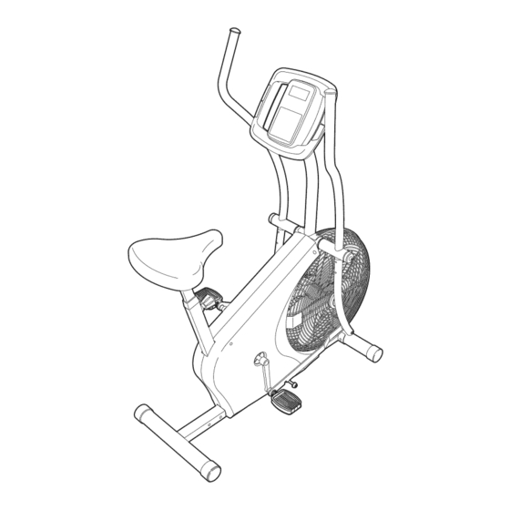
ProForm XP WhirlWind 280 User Manual
831.218223
Hide thumbs
Also See for XP WhirlWind 280:
- User manual (20 pages) ,
- User manual (20 pages) ,
- User manual (20 pages)
Table of Contents

Related Manuals for ProForm XP WhirlWind 280


Summary of Contents for ProForm XP WhirlWind 280
- Page 1 Model No. 831.21822.3 EXERCISE Serial No. User's Manual Write the serial number in the space above for reference. Serial Number Decal • Assembly • Operation • Maintenance • Part List and Drawing Sears, Roebuck and Co. Hoffman Estates, IL 60179...
- Page 2 TABLE OF CONTENTS WARNING DECAL PLACEMENT .............. IMPORTANT PRECAUTIONS ..............BEFORE YOU BEGIN ..............ASSEMBLY ................HOW TO USE THE EXERCISE BIKE ............MAINTENANCE AND TROUBLESHOOTING ........... EXERCISE GUIDELINES ..............PART LIST ................EXPLODED DRAWING ..............ORDERING REPLACEMENT PARTS ..........Back Cover 90 DAY FULL WARRANTY ............
- Page 3 iMPORTANT PRECAUTIONS WARNING: To reduce the risk ofserious niory, read a . mportant precaot ons instructions in this manual and all warnings on your exercise bike before using your exercise bike. Sears assumes no responsibility for personal injury or property damage sustained by or through the use of this product.
- Page 4 BEFORE YOU BEGIN Congratulations for selecting the new PROFORM ®XP after reading this manual, please see the back cover WHIRLWIND 280 exercise bike. Cycling is one of the of this manual. To help us assist you, note the product most effective exercises for increasing cardiovascular model number and serial number before contacting us.
- Page 5 ASSEMBLY Assembly requires two persons. Place all parts of the exercise bike in a cleared area and remove the packing materials. Do not dispose of the packing materials until assembly is completed. in addition to the included tool(s), assembly requires an adjustable wrench and a Phillips screwdriver...
- Page 6 Attach the Front Stabilizer (19) to the front of the Frame (1) with two M10 x 78mm Patch Screws (65). Attach the Rear Stabilizer (60) to the Frame (1) with five M10 x 22mm Patch Screws (4). 4" Loosen the Seat Knob (29) a few turns. Next, pull the Seat Knob outward, insert the Seat Post (6) into the Frame (1), and then release the Seat Knob.
- Page 7 Attach the Seat (20) to the Seat Post (6) with four M8 Locknuts (66) and four M8 Split Washers (72). Note: The Locknuts and Split Washers may be preattached to the under- side of the Seat. Tip: To avoid pinching the Reed Switch Wire (31), position it as shown in the inset draw-...
- Page 8 The Console (3) requires four D batteries (not included); alkaline batteries are recommended. iMPORTANT: if the Console has been exposed to cold temperatures, allow it to Battery warm to room temperature before inserting Cover batteries. Otherwise, you may damage the console displays or other electronic...
- Page 9 Identify the Right Handlebar (9) and the Right Handlebar Base (10), which are marked with "Right" stickers. Orient these parts so that the wide side of the tube on the Right Handlebar and the Right Link Arm (16) are on the same side.
- Page 10 11. Remove the 1/2" Pedal Nut (68) from the shaft of one of the Pedals (23). See the lower draw- ing. Make sure that there is a Custom Washer (86), a Pedal Spring (42), a Blue Washer (71), a Pedal Bushing (43), a Black Pedal Washer (79), and a Pedal Spacer (44) on the shaft of the Pedal.
- Page 11 HOW TO USE THE EXERCISE BiKE HANDLEBAR OPERATION Stationary Mode You can use the handlebars in the dual-action mode, To convert the handlebars to the stationary mode, the for upper- and lower-body exercise, or in the station- link arms must be disconnected from the pedals. Pull ary mode, for pedaling exercise only.
- Page 12 CONSOLE DIAGRAM 2J" TIME ,"% mu m D STANCE SPEED PRIORITY DISPLAY HOW TO USE THE CONSOLE The lower right dis- play can show your Before using the console, make sure that batteries are pedaling speed (in installed (see assembly step 7 on page 8). If there is a miles or kilometers per SPEED sheet of plastic on the display, remove the plastic.
- Page 13 The right display will show a When your pulse is detected, the heart- track that represents 1/4 mile Ill|| (400 meters). As you exercise, shaped indicator in the .50 - - indicators will appear in succes- lower right display will DISTANCE sion around the track until the flash and one or two...
- Page 14 MAINTENANCE AND TROUBLESHOOTING Inspect and tighten all parts of the exercise bike regu- If the Belt (22) needs to be adjusted, first loosen the larly. To clean the exercise bike, use a damp cloth and right Guard Fastener (not shown). To tighten the Belt, a small amount of mild detergent;...
- Page 15 ADJUSTING THE REED SWITCH Next, locate the Reed Switch (31). Turn the Crank Arm (26) until the Magnet (48) is aligned with the Reed Switch. If the console does not display correct feedback, the reed switch should be adjusted. To adjust the reed switch, the Right Shield (18) must be moved.
- Page 16 EXERCISE GUiDELiNES Burning Fat--To burn fat effectively, you must exer- cise at a low intensity level for a sustained period of time, During the first few minutes of exercise, your body uses carbohydrate calories for energy. Only after the first few minutes of exercise does your body begin to use stored fat calories for energy, If your goal is to burn fat, adjust the intensity of your exercise until your heart rate is near the lowest number in your training...
- Page 17 SUGGESTED STRETCHES The correct form for several basic stretches is shown at the right. Move slowly as you stretch--never bounce. 1. Toe Touch Stretch Stand with your knees bent slightly and slowly bend forward from your hips. Allow your back and shoulders to relax as you reach down toward your toes as far as possible.
- Page 18 PART LIST Model No. 831.21822.3 Rll10B Key No. Qty. Description Key No. Qty. Description Frame Link Arm Bushing Upright Seat Guide Console Seat Post Bushing M10 x 22mm Patch Screw Magnet Small Axle Cover Seat Post Small Axle Cap Left Handlebar Fan Washer Left Handlebar Base Eyebolt...
- Page 19 EXPLODED DRAWING Model No. 831.21822.3 Rll10B 49 853j_" 72 66. .-_-48...
- Page 20 Your Home For repair--in your home--of all major brand appliances, lawn and garden equipment, or heating and cooling systems, no matter made it, no matter sold For the replacement parts, accessories, and user's manuals that you need to do-it-yourself. For Sears professional installation of home appliances and items like garage door openers...