Table of Contents
Advertisement
Quick Links
Advertisement
Table of Contents
Troubleshooting

Related Manuals for IBM x3100 M5 Type 5457


Summary of Contents for IBM x3100 M5 Type 5457
- Page 1 System x3100 M5 Type 5457 Installation and Service Guide...
- Page 3 System x3100 M5 Type 5457 Installation and Service Guide...
- Page 4 Appendix D, “Getting help and technical assistance,” on page 651, “Notices” on page 655, the Warranty Information document, and the Safety Information and Environmental Notices and User Guide documents on the IBM Documentation CD. Third Edition (September 2014) © Copyright IBM Corporation 2014.
-
Page 5: Table Of Contents
Setup utility menu choices . . 99 Instructions for IBM Business Partners . . 28 Passwords . . 103 How to send DSA data to IBM . . 28 Using the Boot Manager. . 104 Server components . . 29 Starting the backup server firmware . - Page 6 . 269 Chapter 5. Parts listing, IBM System Removing a memory module . . 272 x3100 M5 Type 5457 ..165 Replacing a memory module . . 274 Removing the system battery .
- Page 7 Getting help and information from the World Wide Replacing the operating temperature . 652 enhancement kit . . 293 How to send DSA data to IBM . 652 Removing and replacing Tier 2 CRUs . . 295 Creating a personalized support web page .
- Page 8 System x3100 M5 Type 5457: Installation and Service Guide...
-
Page 9: Safety
Ennen kuin asennat tämän tuotteen, lue turvaohjeet kohdasta Safety Information. Avant d'installer ce produit, lisez les consignes de sécurité. Vor der Installation dieses Produkts die Sicherheitshinweise lesen. Prima di installare questo prodotto, leggere le Informazioni sulla Sicurezza. © Copyright IBM Corp. 2014... - Page 10 Les sikkerhetsinformasjonen (Safety Information) før du installerer dette produktet. Antes de instalar este produto, leia as Informações sobre Segurança. Antes de instalar este producto, lea la información de seguridad. Läs säkerhetsinformationen innan du installerar den här produkten. viii System x3100 M5 Type 5457: Installation and Service Guide...
-
Page 11: Safety Statements
Safety statements These statements provide the caution and danger information that is used in this documentation. Important: Each caution and danger statement in this documentation is labeled with a number. This number is used to cross reference an English-language caution or danger statement with translated versions of the caution or danger statement in the Safety Information document. - Page 12 There are no serviceable parts inside the device. v Use of controls or adjustments or performance of procedures other than those specified herein might result in hazardous radiation exposure. System x3100 M5 Type 5457: Installation and Service Guide...
- Page 13 DANGER Some laser products contain an embedded Class 3A or Class 3B laser diode. Note the following. Laser radiation when open. Do not stare into the beam, do not view directly with optical instruments, and avoid direct exposure to the beam. Statement 4 CAUTION: Use safe practices when lifting.
- Page 14 There are no serviceable parts inside these components. If you suspect a problem with one of these parts, contact a service technician. Statement 12 CAUTION: The following label indicates a hot surface nearby. Statement 26 System x3100 M5 Type 5457: Installation and Service Guide...
- Page 15 CAUTION: Do not place any object on top of rack-mounted devices. Statement 27 CAUTION: Hazardous moving parts are nearby. Rack Safety Information, Statement 2 DANGER v Always lower the leveling pads on the rack cabinet. v Always install stabilizer brackets on the rack cabinet. v Always install servers and optional devices starting from the bottom of the rack cabinet.
- Page 16 System x3100 M5 Type 5457: Installation and Service Guide...
-
Page 17: Chapter 1. The Ibm System X3100 M5 Type 5457 Server
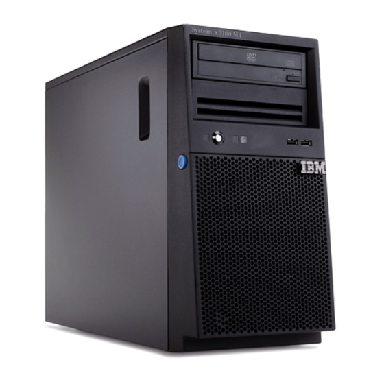
If firmware and documentation updates are available, you can download them from the IBM website. The server might have features that are not described in the documentation that comes with the server, and the documentation might be updated occasionally to include information about those features, or technical updates might be available to provide additional information that is not included in the server documentation. - Page 18 Note: The illustrations in this document might differ slightly from your hardware. Model number and serial number Figure 1. Location of model type/serial number of the 4U server model with non-hot-swap power supplies System x3100 M5 Type 5457: Installation and Service Guide...
- Page 19 The following illustration shows the QR code (http://ibm.co/1ja7bP8): Figure 3. QR code You can download the IBM ServerGuide Setup and Installation CD to help you configure the hardware, install device drivers, and install the operating system. Chapter 1. The IBM System x3100 M5 Type 5457 server...
-
Page 20: The Ibm Documentation Cd
For a list of supported optional devices for the server, see http://www.ibm.com/ systems/info/x86servers/serverproven/compat/us. See the Rack Installation Instructions document on the IBM System x Documentation CD for complete rack installation and removal instructions. The IBM Documentation CD The IBM Documentation CD contains documentation for the server in Portable Document Format (PDF) and includes the IBM Documentation Browser to help you find information quickly. -
Page 21: Related Documentation
The following documentation also comes with the server: v Warranty Information This document is in printed format and comes with the server. It contains warranty terms and a pointer to the IBM Statement of Limited Warranty on the IBM website. v Important Notices This document is in printed format and comes with the server. -
Page 22: Notices And Statements In This Document
These updates are available from the IBM website. To check for updates, go to http://www.ibm.com/supportportal. Notices and statements in this document The caution and danger statements in this document are also in the multilingual Safety Information document, which is on the IBM Documentation CD. - Page 23 20°C per hour (68°F per hour) for hard disk drives v Power off: – Temperature: 5°C to 45°C (41°F to 113°F) – Humidity: 8%~85% – Maximum dew point: 27°C (80.6°F) v Storage (non-operating): Chapter 1. The IBM System x3100 M5 Type 5457 server...
- Page 24 – One internal USB 2.0 port for an optional tape drive v Six SATA ports (blue-colored ports for DVD drive or optional tape drive) v One serial port v Two Ethernet ports v One VGA port Heat output: Approximate heat output: System x3100 M5 Type 5457: Installation and Service Guide...
- Page 25 For more information on the energy efficiency program, go to http://www.ibm.com/systems/x/hardware/energy-star/index.html Product Type: Computer server Year first manufactured: 2014 Internal/external power supply efficiency: v http://www.plugloadsolutions.com/psu_reports/IBM_DPS-430EB %20A_430W_SO-385_Report.pdf v http://www.plugloadsolutions.com/psu_reports/DELTA %20ELECTRONICS_DPS-300AB-62%20A_ECOS %202471_300W_Report.pdf Chapter 1. The IBM System x3100 M5 Type 5457 server...
- Page 26 1. Use the Setup utility to determine the type and speed of the microprocessors in the server 2. For a list of supported microprocessors, see http://www.ibm.com/ systems/info/x86servers/serverproven/compat/us. Memory: v Connectors: four dual inline memory module (DIMM) connectors, two-way interleaved System x3100 M5 Type 5457: Installation and Service Guide...
- Page 27 – Altitude: 3,050 m (10,000) – Humidity: 5%~80% – Maximum dew point: 29°C (84.2°F) v Shipment (non-operating) – Temperature: -40°C to 60°C (-40°F to 140°F) – Altitude: 10.700 m (35,105 ft) Chapter 1. The IBM System x3100 M5 Type 5457 server...
- Page 28 Minimum configuration: 341 Btu per hour (100 watts) v Maximum configuration: 1726 Btu per hour (506 watts) Expansion slots: v One PCI Express x16 slot v One PCI Express x8 slot v One PCI Express x8 slot System x3100 M5 Type 5457: Installation and Service Guide...
- Page 29 2014 Internal/external power supply efficiency: v http://www.plugloadsolutions.com/psu_reports/IBM_DPS-430EB %20A_430W_SO-385_Report.pdf v http://www.plugloadsolutions.com/psu_reports/DELTA %20ELECTRONICS_DPS-300AB-62%20A_ECOS %202471_300W_Report.pdf Maximum power (watts): See Power supply. Idle state power (watts): Sleep mode power (watts): Not applicable for servers. Chapter 1. The IBM System x3100 M5 Type 5457 server...
-
Page 30: What Your Server Offers
Integrated management module II (IMM2) The integrated management module II (IMM2) is the second generation of the IMM. The IMM2 is the common management controller for IBM System x hardware. The IMM2 consolidates multiple management functions in a single chip on the server system board. - Page 31 The server provides a QR code on the system service label, which is on the cover of the server, that you can scan using a QR code reader and scanner with a mobile device to get quick access to the IBM Service Information website. The IBM Service Information website provides additional information for parts installation and replacement videos, and error codes for server support.
- Page 32 By using industry standards, IBM Systems Director supports multiple operating systems and virtualization technologies for IBM and non-IBM x86 platforms. For more information, see the IBM Systems Director Information Center at and “IBM Systems Director” on page 18. v IBM Enterprise X-Architecture technology ®...
-
Page 33: Reliability, Availability, And Serviceability
Read-only memory (ROM) checksums v Redundant Ethernet capabilities (requires an optional Ethernet adapter) with failover support v ROM-based diagnostic programs 2. Service availability will vary by country. Response time varies; may exclude holidays. Chapter 1. The IBM System x3100 M5 Type 5457 server... -
Page 34: Ibm Systems Director
A set of common tasks that are included with IBM Systems Director provides many of the core capabilities that are required for basic management, which means instant out-of-the-box business value. -
Page 35: Server Controls, Leds, And Power
LED(green) Hard disk drive DVD-eject activity LED button Power-control USB 1 button USB 2 Power-on LED Figure 4. Front view of 4U server model with non-hot-swap power supplies (bezel installed) Chapter 1. The IBM System x3100 M5 Type 5457 server... - Page 36 DVD-eject button Front information panel USB 2 USB 1 DVD drive activity LED (green) Figure 6. Front view of 5U server model with hot-swap power supplies (lower and upper bezel installed) System x3100 M5 Type 5457: Installation and Service Guide...
- Page 37 (Four 3.5" hard disk drive configuration) v Power control button and power-on LED: Press this button to turn the server on and off manually. The states of the power-on LED are as follows: Chapter 1. The IBM System x3100 M5 Type 5457 server...
- Page 38 (three flashes per second), the adapter is identifying the drive. When the drive is removed, this LED also is visible on the SAS/SATA backplane, below the hot-swap hard disk drive activity LED. System x3100 M5 Type 5457: Installation and Service Guide...
-
Page 39: Rear View
USB connectors Ethernet link status Ethernet connector 2 Ethernet transmit/ receive activity Figure 10. Rear view of 4U server model with non-hot-swap power supplies (power supply LEDs present) Chapter 1. The IBM System x3100 M5 Type 5457 server... - Page 40 It allows you to blue screen the server and take a memory dump (use this button only when directed by the IBM service support). You might have to use a pen or the end of a straightened paper clip to press the button.
-
Page 41: Server Power Features
PCI options. 2. When you turn on the server with external graphical adapters installed, the IBM logo displays on the screen after approximately 3 minutes. This is normal operation while the system loads. 3. Make sure the left-side cover is closed. -
Page 42: Turning Off The Server
The server can be turned off by Wake on LAN feature with the following limitation: v The integrated management module II (IMM2) can turn off the server as an automatic response to a critical system failure. System x3100 M5 Type 5457: Installation and Service Guide... -
Page 43: Chapter 2. Installing Optional Devices
In addition to the instructions in this chapter for installing optional hardware devices, updating the firmware and device drivers, and completing the installation, IBM Business Partners must also complete the steps in “Instructions for IBM Business Partners” on page 28. -
Page 44: Instructions For Ibm Business Partners
2. Shut down and restart the server multiple times to ensure that the server is correctly configured and functions correctly with the newly installed devices. 3. Save the DSA log as a file and send it to IBM. For information about transferring data and logs, see “How to send DSA data to IBM.”... -
Page 45: Server Components
Server components The section shows the major components in the server. The following illustration shows the server components in 4U server models with non-hot-swap power supplies. The illustrations in this document might differ slightly from your hardware. System fan (rear) Operator information panel assembly Memory... -
Page 46: System-Board Internal Connectors
System-board internal connectors This section contains information regarding the system board internal connectors. The following illustration shows the internal connectors on the system board. System x3100 M5 Type 5457: Installation and Service Guide... -
Page 47: System-Board External Connectors
Microprocessor power connector Fan 1 connector PCI slot 1 PCI slot 2 PCI slot 3 PCI slot 4 Power supply connector Fan 2 connector USB hypervisor Microprocessor connector USB tape drive Thermal connector sensor connector Front USB connector SATA5 HDD backplane SATA4 power connector SATA3... -
Page 48: System-Board Switches And Jumpers
Ethernet connector 2/ USB connectors 3&4 NMI button Serial (COM1) Video Figure 15. External connectors on system board System-board switches and jumpers This section contains information regarding the system board switches and jumpers. System x3100 M5 Type 5457: Installation and Service Guide... - Page 49 Low security jumper (J12) IMM SPI enable jumper (OVR 1) UEFI boot backup jumper (J16) System TPM physical jumper (SW1) Clear CMOS jumper (CLR RTC 1) Figure 16. Location and description of switches and jumpers The following table describes the functions of switches and jumpers on the system board.
-
Page 50: System-Board Leds
Before you disconnect the power source, make a note of which LEDs are lit, including the LEDs that are lit on the operation information panel and LEDs inside the server on the system board. System x3100 M5 Type 5457: Installation and Service Guide... -
Page 51: Installation Guidelines
Installation guidelines Use the installation guidelines to install the IBM System x3100 M5 Type 5457. Attention: Static electricity that is released to internal server components when the server is powered-on might cause the system to halt, which might result in the loss of data. -
Page 52: System Reliability Guidelines
You have replaced a hot-swap drive within 2 minutes of removal. v You do not operate the server without the air baffle installed. Operating the server without the air baffle might cause the microprocessor to overheat. System x3100 M5 Type 5457: Installation and Service Guide... -
Page 53: Working Inside The Server With The Power On
Working inside the server with the power on Guidelines to work inside the server with the power on. Attention: Static electricity that is released to internal server components when the server is powered-on might cause the server to halt, which might result in the loss of data. -
Page 54: Removing The Side Cover
For the 5U server model with hot-swap power supplies, complete the following steps to remove the side cover. For 4U server models with non-hot-swap power supplies, please see the above sub-section. System x3100 M5 Type 5457: Installation and Service Guide... -
Page 55: Removing The Air Baffle
1. Read the safety information in “Safety” on page vii and “Installation guidelines” on page 35. 2. Turn off the server and peripheral devices and disconnect the power cords and all external cables (see “Turning off the server” on page 26). 3. -
Page 56: Removing The Bezel
2. Press the button on the left edge of the bezel; then, rotate the left side of the bezel away from the server until it disengages and set it aside. Note: When rotating the bezel to a certain point, it may automatically disengage from the chassis. System x3100 M5 Type 5457: Installation and Service Guide... - Page 57 Figure 21. Bezel removal for 4U server model with non-hot-swap power supplies (1) Figure 22. Bezel removal for 4U server model with non-hot-swap power supplies (2) 3. If you are instructed to return the bezel, follow all packaging instructions, and use any packaging materials for shipping that are supplied to you.
-
Page 58: Removing The Lower Bezel
Figure 23. Lower bezel removal for 5U server model with hot-swap power supplies 4. If you are instructed to return the lower bezel, follow all packaging instructions, and use any packaging materials for shipping that are supplied to you. System x3100 M5 Type 5457: Installation and Service Guide... -
Page 59: Removing The Upper Bezel
Removing the upper bezel This procedure applies only to the 5U server model with hot-swap power supplies. To access the DVD drive or tape drive on the 5U server model with hot-swap power supplies, you must first remove the upper bezel to access the devices. To remove the upper bezel on the 5U server model with hot-swap power supplies, complete the following steps. -
Page 60: Installing A Memory Module
- 4 = quad-rank – ff is the device organization (bit width) - 4 = x4 organization (4 DQ lines per SDRAM) - 8 = x8 organization - 16 = x16 organization System x3100 M5 Type 5457: Installation and Service Guide... -
Page 61: Unbuffered Dimms (Udimms)
– wwwww is the DIMM bandwidth, in MBps - 8500 = 8.53 GBps (PC3-1066 SDRAMs, 8-byte primary data bus) - 10600 = 10.66 GBps (PC3-1333 SDRAMs, 8-byte primary data bus) - 12800 = 12.8 GBps (PC3-1600 SDRAMs, 8-byte primary data bus) –... - Page 62 For the 5U server model with hot-swap power supplies, please see the next sub-section. 1. Read the safety information in “Safety” on page vii and “Installation guidelines” on page 35. System x3100 M5 Type 5457: Installation and Service Guide...
- Page 63 2. Turn off the server and peripheral devices, and disconnect the power cords and all external cables. 3. Carefully turn the server on its side so that it is lying flat, with the cover facing up. Attention: Do not allow the server to fall over. 4.
- Page 64 DIMM, and then reinsert it. 11. If you have other devices to install, do so now. Otherwise, go to “Completing the installation” on page 82. System x3100 M5 Type 5457: Installation and Service Guide...
-
Page 65: Installing Drives
Installing drives Use this information to install drives. Depending on the server model, a DVD-ROM or multiburner drive might be installed in the server. For 4U server models with non-hot-swap power supplies, the server supports up to four 3.5-inch simple-swap SATA hard disk drives (depending on the model). - Page 66 Figure 30. Location of the four 3.5" hot-swap hard disk drive bays in the 5U server model with hot-swap power supplies The following notes describe the types of drives that the server supports and other information that you must consider when installing a drive: System x3100 M5 Type 5457: Installation and Service Guide...
-
Page 67: Installing A Dvd Drive
PCI adapter or PCI Express adapter slot cover in the event that you later remove the device. v For a complete list of supported options for the server, see http:// www.ibm.com/systems/info/x86servers/serverproven/compat/us. Installing a DVD drive Use this information to install a DVD drive... - Page 68 2. Slide the drive retainer clip to the front to remove it from the drive cage; then, snap the drive retainer clip into the screw holes on the side of the drive. 10. Push the drive into the bay. System x3100 M5 Type 5457: Installation and Service Guide...
- Page 69 Drive retainer clip Figure 31. DVD drive installation for 4U server models with non-hot-swap power supplies 11. Carefully turn the server on its side so that it is lying flat. Attention: Do not allow the server to fall over. 12. Connect the power (power connector P9) and signal cables to the drive. Note: Route the signal cable so that it does not block the airflow to the rear of the drives or over the microprocessor and dual inline memory modules (DIMMs).
- Page 70 (DIMMs). If you have other devices to install, do so now. Otherwise, go to “Completing the installation” on page 82. System x3100 M5 Type 5457: Installation and Service Guide...
-
Page 71: Installing A Tape Drive
Installing a tape drive Use this information to install a tape drive If you are replacing a drive, make sure that: v You have all the cables and other equipment that is specified in the documentation that comes with the new drive. v You check the instructions that come with the new drive to determine whether you must set any switches or jumpers on the drive. - Page 72 7. Set any jumpers or switches on the drive according to the documentation that comes with the drive. System x3100 M5 Type 5457: Installation and Service Guide...
- Page 73 8. Remove the filler from the drive cage, if any is present. 9. Slide the drive retainer clip to the front to remove it from the drive cage of bay 2; then, snap the drive retainer clip into the screw holes on the side of the drive.
-
Page 74: Installing A Simple-Swap Hard Disk Drive
– Hard disk drive 2 connects to the SATA 2 connector on the system board. – Hard disk drive 3 connects to the SATA 3 connector on the system board. Note: Under RAID mode: 1. In uEFI setup menu: System x3100 M5 Type 5457: Installation and Service Guide... - Page 75 v Drive 0 indicates hard disk drive 0. v Drive 1 indicates hard disk drive 1. v Drive 2 indicates hard disk drive 2. v Drive 3 indicates hard disk drive 3. 2. In MegaRAID Storage Manager utility: v Slot 0 indicates hard disk drive 0. v Slot 1 indicates hard disk drive 1.
-
Page 76: Installing A Hot-Swap Hard Disk Drive
To install a hot-swap hard disk drive on the 5U server model that have hot-swap power supplies, complete the following steps. The following illustration shows the installation of a 2.5" hot swap hard disk into a 5U server model with hot-swap power supplies. System x3100 M5 Type 5457: Installation and Service Guide... - Page 77 Release latch Activity LED (green) Error LED (yellow) 2.5-inch hot-swap Drive handle hard disk drive Figure 37. 2.5" hot swap hard disk drive installation for 5U server model with hot-swap power supplies The following illustration shows the installation of a 3.5" hot swap hard disk into a 5U server model with hot-swap power supplies.
-
Page 78: Installing An Adapter
6. Carefully turn the server on its side so that it is lying flat, with the cover facing up. Attention: Do not allow the server to fall over. 7. Remove the side cover (see “Removing the side cover” on page 38). System x3100 M5 Type 5457: Installation and Service Guide... - Page 79 8. Remove the air baffle (see “Removing the air baffle” on page 39). 9. Follow the cabling instructions, if any, that come with the adapter. Route the adapter cables before you install the adapter. 10. Follow the instructions that come with the adapter to set jumpers or switches, if any.
- Page 80 Figure 41. Rear adapter retention bracket installation for 4U server model with non-hot-swap power supplies 16. Rotate the rear adapter retention bracket into place so that the hole in the opposite hinge point snaps into place over the hinge pin on the chassis. System x3100 M5 Type 5457: Installation and Service Guide...
- Page 81 17. Connect any required cables to the adapter. Route the cables so that they do not block the flow of air from the system fan. 18. Install the air baffle (see “Replacing the air baffle” on page 185). If you have other devices to install, do so now. Otherwise, go to “Completing the installation”...
-
Page 82: Installing A Microprocessor And Heat Sink
Then, remove the microprocessor from the package. 7. Remove the protective cover, tape, or label from the surface of the microprocessor socket, if any is present. System x3100 M5 Type 5457: Installation and Service Guide... - Page 83 8. Rotate the release lever on the microprocessor socket to the fully open position. Attention: Make sure that the release lever on the microprocessor socket is in the fully open position before you insert the microprocessor in the socket. Failure to do so might result in permanent damage to the microprocessor, microprocessor socket, and system board.
- Page 84 2. Turn off the server and all attached devices; then, disconnect all power cords and external cables. 3. Unlock and remove the side cover (see “Removing the side cover” on page 38). System x3100 M5 Type 5457: Installation and Service Guide...
- Page 85 4. Carefully turn the server on its side so that it is lying flat, with the system board facing up. Attention: Do not allow the server to fall over. 5. Touch the static-protective package that contains the microprocessor to any unpainted metal surface on the server.
- Page 86 12. Rotate the rear adapter-retention bracket to the closed (locked) position. If you have other devices to install, do so now. Otherwise, go to “Completing the installation” on page 82. System x3100 M5 Type 5457: Installation and Service Guide...
-
Page 87: Thermal Grease
Thermal grease The thermal grease must be replaced whenever the heat sink has been removed from the top of the microprocessor and is going to be reused or when debris is found in the grease. Use this information to replace damaged or contaminated thermal grease on the microprocessor and heat sink. -
Page 88: Installing The Non-Hot-Swap Power Supply
5. Remove the side cover (see “Removing the side cover” on page 38). 6. Remove the air baffle (see “Removing the air baffle” on page 39). 7. Remove the heat sink (see “Removing the microprocessor and heat sink” on page 300). System x3100 M5 Type 5457: Installation and Service Guide... - Page 89 8. Position the power supply in the chassis so that the screw holes in the power supply are aligned with the corresponding holes in the rear of the chassis. Figure 49. Non-hot-swap power supply alignment with chassis for 4U server models with non-hot-swap power supplies Note: Make sure the top and the bottom of the power supply align with the upper and lower tabs on the opening.
-
Page 90: Installing The Hot-Swap Power Supply
The device also might have more than one power cord. To remove all electrical current from the device, ensure that all power cords are disconnected from the power source. Statement 8 System x3100 M5 Type 5457: Installation and Service Guide... - Page 91 CAUTION: Never remove the cover on a power supply or any part that has the following label attached. Hazardous voltage, current, and energy levels are present inside any component that has this label attached. There are no serviceable parts inside these components.
-
Page 92: Installing The Thermal Solution Fan Kit
2. When you install a second adapter in the adapter slots on the system board, you must install the IBM Thermal Solution Fan kit option to ensure proper cooling and airflow to the system. For 4U server models with non-hot-swap power supplies, the part number is 46W9177. - Page 93 3. Carefully turn the server on its side so that it is lying flat, with the cover facing Attention: Do not allow the server to fall over. 4. Remove the side cover (see “Removing the side cover” on page 38). 5.
-
Page 94: Installing The Battery Holder Into 5U Server Model
3. Unlock and remove the side cover (see “Removing the side cover” on page 38). 4. Carefully turn the server on its side so that it is lying flat, with the cover facing Attention: Do not allow the server to fall over. System x3100 M5 Type 5457: Installation and Service Guide... - Page 95 5. Insert the battery holder into the bracket. Battery holder Figure 54. Battery holder insertion into bracket for 5U server models with hot-swap power supplies 6. Tighten the screw to secure the battery holder and bracket to the chassis. Figure 55. Securing battery holder to chassis for 5U server models with hot-swap power supplies 7.
-
Page 96: Installing The Operating Temperature Enhancement Kit
Figure 56. Thermal sensor installation for 4U server models with non-hot-swap power supplies 7. Connect the thermal sensor connector to the system board and remember to close the cable clips to secure the cable. System x3100 M5 Type 5457: Installation and Service Guide... - Page 97 Thermal sensor Figure 57. Installing thermal sensor connector to system board for 4U server model with non-hot-swap power supplies 8. If you have other devices to install, do so now. Otherwise, go to “Completing the installation” on page 82. To install the operating temperature enhancement kit on 5U server models with hot-swap power supplies, complete the following steps.
-
Page 98: Completing The Installation
8. Start the server. Confirm that it starts correctly and recognizes the newly installed devices, and make sure that no error LEDs are lit. 9. (IBM Business Partners only) Complete the additional steps in “Instructions for IBM Business Partners” on page 28. -
Page 99: Replacing The Bezel
Replacing the bezel This procedure applies only to 4U server models with non-hot-swap power supplies. To install the bezel on 4U server models with non-hot-swap power supplies, complete the following steps. 1. Read the safety information in “Safety” on page vii and “Installation guidelines”... -
Page 100: Replacing The Lower Bezel
1. Read the safety information in “Safety” on page vii and “Installation guidelines” on page 35. 2. Insert the two tabs on the right-side of the upper bezel into the corresponding holes on the right side of the chassis. System x3100 M5 Type 5457: Installation and Service Guide... -
Page 101: Replacing The Air Baffle
Bezel clips Figure 61. Upper bezel installation for 5U server model with hot-swap power supplies 3. Rotate the upper bezel to the left side of the chassis until the bezel clips are aligned with the corresponding indentations on the left side of the chassis and snap them into place. - Page 102 For proper cooling and airflow, reinstall the air baffle before you turn on the server. Operating the server with the air baffle removed might damage server components. System x3100 M5 Type 5457: Installation and Service Guide...
-
Page 103: Replacing The Side Cover
Air baffle Figure 63. Air baffle installation for 4U server model with non-hot-swap power supplies Replacing the side cover Use this information to replace the side cover. Attention: For proper cooling and airflow, replace the side cover before turning on the server. Operating the server for extended periods of time (more than 30 minutes) with the side cover removed might damage server components. - Page 104 Press down on the cover release latch and push the cover into the chassis until it latches securely into place. System x3100 M5 Type 5457: Installation and Service Guide...
-
Page 105: Connecting The Cables
Cover-release latch Key lock Figure 65. Side cover installation for 5U server model with hot-swap power supplies 5. Lock the side cover. Connecting the cables Use this information to connect the cables. Attention: To prevent damage to equipment, connect the power cords last. If the server cables and connector panel have color-coded connections, match the color of the cable end with the color of the connector. - Page 106 1 Ethernet USB connectors connector 2 Ethernet link status LED Ethernet transmit/ receive activity LED Figure 67. Input/output (I/O) connectors on the rear of 5U server models with hot-swap power supplies System x3100 M5 Type 5457: Installation and Service Guide...
-
Page 107: Updating The Server Configuration
To convert the server from a tower model to a rack model, you must use a Tower-to-Rack Kit. You can then install the server in a rack cabinet. To order a Tower-to-Rack Kit for the server, contact your IBM marketing representative or authorized reseller. - Page 108 67 mm. In light of this distance, please make sure your rack cabinet door can fully close before you begin to install the system in the rack cabinet. System x3100 M5 Type 5457: Installation and Service Guide...
-
Page 109: Chapter 3. Configuration Information And Instructions
The firmware for the server is periodically updated and is available for download on the IBM website. To check for the latest level of firmware, such as the UEFI firmware, device drivers, and integrated management module (IMM) firmware, go to http://www.ibm.com/support/fixcentral. -
Page 110: Configuring The Server
Remote presence capability and blue-screen capture The remote presence and blue-screen capture features are integrated functions of the integrated management module (IMM2). The remote presence feature provides the following functions: System x3100 M5 Type 5457: Installation and Service Guide... - Page 111 UEFI settings from the command line without the need to restart the server to run the Setup utility. For more information about using this program, see “IBM Advanced Settings Utility program” on page 111. v Configuring RAID arrays For information about configuring RAID arrays, see “Configuring RAID arrays”...
-
Page 112: Using The Serverguide Setup And Installation Cd
1. For more information about the Human Interface Infrastructure (HII) and SAS2IRCU, go to http://www.ibm.com/support/entry/portal/ docdisplay?lndocid=MIGR-5088601. 2. For more information about the MegaRAID, go to http://www.ibm.com/ support/entry/portal/docdisplay?lndocid=MIGR-5073015. Using the ServerGuide Setup and Installation CD Use this information as an overview for using the ServerGuide Setup and Installation CD. -
Page 113: Setup And Configuration Overview
When you use the ServerGuide Setup and Installation CD, you do not need setup diskettes. You can use the CD to configure any supported IBM server model. The setup program provides a list of tasks that are required to set up your server model. -
Page 114: Installing Your Operating System Without Using Serverguide
Setup utility menu. If you do not type the administrator password, a limited Setup utility menu is available. 3. Select settings to view or change. System x3100 M5 Type 5457: Installation and Service Guide... -
Page 115: Setup Utility Menu Choices
Setup utility menu choices Use the Setup utility main menu to view and configure server configuration data and settings. The following choices are on the Setup utility main menu for the UEFI. Depending on the version of the firmware, some menu choices might differ slightly from these descriptions. - Page 116 POST Watchdog Timer Select this choice to view or enable the POST watchdog timer. v POST Watchdog Timer Value Select this choice to view or set the POST loader watchdog timer value. System x3100 M5 Type 5457: Installation and Service Guide...
- Page 117 v Reboot System on NMI Select this choice to enable or disable restarting the system whenever a nonmaskable interrupt (NMI) occurs. Enable is the default. v Halt on Severe Error Select this choice to enable or disable the system from booting into OS, displaying the POST event viewer whenever a severe error was detected.
- Page 118 Select this choice to exit from the Setup utility. If you have not saved the changes that you have made in the settings, you are asked whether you want to save the changes or exit without saving them. System x3100 M5 Type 5457: Installation and Service Guide...
-
Page 119: Passwords
Passwords From the User Security menu choice, you can set, change, and delete a power-on password and an administrator password. The User Security menu choice is on the full Setup utility menu only. If you set only a power-on password, you must type the power-on password to complete the system startup and to have access to the full Setup utility menu. -
Page 120: Using The Boot Manager
After the primary copy is restored, turn off the server; then, change back the position of the UEFI boot backup switch (change switch 1 of the SW4 to the off position). System x3100 M5 Type 5457: Installation and Service Guide... -
Page 121: The Updatexpress System Pack Installer
For additional information and to download the UpdateXpress System Pack Installer, go to the ToolsCenter for System x and BladeCenter at http://publib.boulder.ibm.com/infocenter/toolsctr/v1r0/ and click UpdateXpress System Pack Installer. Using the Integrated Management Module II (IMM2) -
Page 122: Using The Remote Presence And Blue-Screen Capture Features
The blue-screen capture feature captures the video display contents before the IMM restarts the server when the IMM detects an operating-system hang condition. A system administrator can use the blue-screen capture to assist in determining the cause of the hang condition. System x3100 M5 Type 5457: Installation and Service Guide... -
Page 123: Obtaining The Imm Host Name
Obtaining the IMM host name Use this information to obtain the IMM host name. About this task If you are logging on to the IMM for the first time after installation, the IMM defaults to DHCP. If a DHCP server is not available, the IMM uses a static IP address of 192.168.70.125. -
Page 124: Logging On To The Web Interface
By default, the icmp packet is blocked by Windows firewall. The IMM GUI will then change to “OS booted” status after you change the setting as indicated above in both the Web and CLI interfaces. System x3100 M5 Type 5457: Installation and Service Guide... -
Page 125: Using The Embedded Hypervisor
Using the embedded hypervisor The VMware ESXi embedded hypervisor software is available on the optional IBM USB flash device with embedded hypervisor. About this task The USB flash device can be installed in USB connectors on the system board (see “System-board internal connectors”... -
Page 126: Configuring The Gigabit Ethernet Controller
(power cycle). For more information on Features on Demand (FoD), including instructions for automating the activation and installation of the activation key by using IBM ToolsCenter or IBM Director, see the IBM System x Features on Demand User's Guide at/http://www.ibm.com/systems/x/fod/ under the Help section. -
Page 127: Enabling Features On Demand Raid Software
You can activate the Features on Demand (FoD) software upgrade key for RAID that is integrated in the integrated management module. For more information and instructions for activating the Features on Demand RAID software key, see the IBM Features on Demand User’s Guide. To download the document, go to /http://www.ibm.com/systems/x/fod/, log in, and click Help. -
Page 128: Updating Ibm Systems Director
Use this information to update the IBM Systems Director. About this task If you plan to use IBM Systems Director to manage the server, you must check for the latest applicable IBM Systems Director updates and interim fixes. Note: Changes are made periodically to the IBM website. The actual procedure might vary slightly from what is described in this document. -
Page 129: Installing Updates With Your Management Server Is Not Connected To The Internet
The ASU is an online tool that supports several operating systems. Make sure that you download the version for your operating system. You can download the ASU from the IBM Web site. To download the ASU and update the UUID, complete the following steps. - Page 130 SYSTEM_PROD_DATA.SysInfoUUID <uuid_value> v Online KCS access (unauthenticated and user restricted): You do not need to specify a value for access_method when you use this access method. Example: asu set SYSTEM_PROD_DATA.SysInfoUUID <uuid_value> System x3100 M5 Type 5457: Installation and Service Guide...
- Page 131 See the Advanced Settings Utility Users Guide for more details. You can access the ASU Users Guide from the IBM website. Note: Changes are made periodically to the IBM website. The actual procedure might vary slightly from what is described in this document.
-
Page 132: Updating The Dmi/Smbios Data
UEFI-based server. The ASU is an online tool that supports several operating systems. Make sure that you download the version for your operating system. You can download the ASU from the IBM website. To download the ASU and update the DMI, complete the following steps. - Page 133 ASU provides the corresponding mapping layer. To download the Advanced Settings Utility Users Guide, complete the following steps: Note: Changes are made periodically to the IBM website. The actual procedure might vary slightly from what is described in this document. a. Go to http://www.ibm.com/supportportal.
- Page 134 You can also build a bootable media using the applications available through the ToolsCenter website at http://www.ibm.com/support/entry/portal/ docdisplay?lndocid=TOOL-CENTER. From the IBM ToolsCenter page, scroll down for the available tools. 5. Restart the server. System x3100 M5 Type 5457: Installation and Service Guide...
-
Page 135: Chapter 4. Troubleshooting
Diagnosing a problem Before you contact IBM or an approved warranty service provider, follow these procedures in the order in which they are presented to diagnose a problem with your server. - Page 136 UpdateXpress System Pack contains an integration-tested bundle of online firmware and device-driver updates for your server. In addition, you can use IBM ToolsCenter Bootable Media Creator to create bootable media that is suitable for applying firmware updates and running preboot diagnostics.
-
Page 137: Undocumented Problems
Problem determination information is available for many devices such as RAID and network adapters. For problems with operating systems or IBM software or devices, go to http://www.ibm.com/supportportal. 7. Check for troubleshooting procedures and RETAIN tips. Troubleshooting procedures and RETAIN tips document known problems and suggested solutions. -
Page 138: Service Bulletins
Service bulletins IBM continually updates the support website with the latest tips and techniques that you can use to solve problem that you might have with the IBM System x3100 M5 server. To find service bulletins that are available for the IBM IBM System x3100 M5 server, go to http://www.ibm.com/supportportal/ and search for 5457, and... -
Page 139: Performing The Checkout Procedure
Check the power supply LEDs (see “Power-supply LEDs” on page 129). b. Turn off the server and all external devices. c. Check all internal and external devices for compatibility at http://www.ibm.com/systems/info/x86servers/serverproven/compat/us. d. Check all cables and power cords. e. Set all display controls to the middle positions. -
Page 140: Diagnostic Tools
327, and the Integrated Management Module II User's Guide at http://www-947.ibm.com/support/entry/portal/docdisplay?lndocid=migr- 5086346. v IBM Dynamic System Analysis Two editions of IBM Dynamic System Analysis (DSA) are available for diagnosing problems, DSA Portable and DSA Preboot: – DSA Portable DSA Portable collects and analyzes system information to aid in diagnosing server problems. - Page 141 (IMM) event log (as the ASM event log), and the operating-system event logs. You can send the DSA log as a file to IBM Support (when requested by IBM Support) or view the information as a text file or HTML file.
-
Page 142: Light Path Diagnostics
When this yellow LED is lit, it indicates that a system error has occurred. An LED on the system board might also be lit to help isolate the error. See“Diagnostic tools” on page 124 for additional information. System x3100 M5 Type 5457: Installation and Service Guide... -
Page 143: Error Leds
The illustration shows the system-board LEDs. The system board has error LEDs that will help to locate the source of the error. Run the diagnostic programs to find out the cause of the error (see “IBM Dynamic System Analysis” on page 136). Microprocessor... - Page 144 If an action step is preceded by “(Trained technician only)”, that step must be performed only by a trained technician. v Go to the IBM support website at http://www.ibm.com/supportportal to check for technical information, hints, tips, and new device drivers or to submit a request for information.
-
Page 145: Power-Supply Leds
If an action step is preceded by “(Trained technician only)”, that step must be performed only by a trained technician. v Go to the IBM support website at http://www.ibm.com/supportportal to check for technical information, hints, tips, and new device drivers or to submit a request for information. - Page 146 Ethernet link status Ethernet connector 2 Ethernet transmit/ receive activity Figure 71. LEDs and connectors on the rear of the 4U server model with non-hot-swap power supplies (power supply LEDs present) System x3100 M5 Type 5457: Installation and Service Guide...
- Page 147 Power connectors AC Power LED (green) DC power LED (green) Fault (error)LED (yellow) Serial (Com1) Ethernet Video connector 1 Ethernet USB connectors connector 2 Ethernet link status LED Ethernet transmit/ receive activity LED Figure 72. LEDs and connectors on the rear of the 5U server model with hot-swap power supplies The following table describes the problems that are indicated by various combinations of the power-supply LEDs and suggested actions to correct the...
-
Page 148: System Pulse Leds
4. If this LED does not blink within 30 seconds of connecting a power source to the server, (trained technician only) replace the system board. System x3100 M5 Type 5457: Installation and Service Guide... -
Page 149: Event Logs
You can view the DSA event log through the DSA program (see “Viewing event logs without restarting the server” on page 134). For more information about DSA and DSA messages, see “IBM Dynamic System Analysis” on page 136 and Appendix C, “DSA diagnostic test results,” on page 515. -
Page 150: Viewing Event Logs Through The Setup Utility
The following table describes the methods that you can use to view the event logs, depending on the condition of the server. The first three conditions generally do not require that you restart the server. System x3100 M5 Type 5457: Installation and Service Guide... -
Page 151: Clearing The Event Logs
Run DSA Portable to view the diagnostic event log (requires IPMI driver) or create an output file that you can send to IBM service and support (using ftp or local copy). v Use IPMItool to view the system-event log (requires IPMI driver). -
Page 152: Post
If POST detects a problem, an error message is sent to the POST event log, see “Event logs” on page 133 for more information. IBM Dynamic System Analysis IBM Dynamic System Analysis (DSA) collects and analyzes system information to aid in diagnosing server problems. DSA collects the following information about the server:... -
Page 153: Dsa Editions
It is provided in the flash memory on the server, or you can create a bootable media such as a CD, DVD, ISO, USB, or PXE using the IBM ToolsCenter Bootable Media Creator (BoMC). For more details, see the BoMC User Guide at http://www.ibm.com/support/entry/portal/... -
Page 154: Running Dsa Preboot Diagnostic Programs
If the server stops during testing and you cannot continue, restart the server and try running the DSA Preboot diagnostic programs again. If the problem remains, replace the component that was being tested when the server stopped. System x3100 M5 Type 5457: Installation and Service Guide... -
Page 155: Diagnostic Text Messages
If you are running the DSA interactive menu (CLI), type :x to exit the Execute Tests menu; then, select completed tests to view the results. Results You can also send the DSA error log to IBM support to aid in diagnosing the server problems. Automated service request (call home) IBM provides tools that can automatically collect and send data or call IBM Support when an error is detected. -
Page 156: Ibm Electronic Service Agent
IBM Support. You can also choose to collect data manually. It uses minimal system resources, and can be downloaded from the IBM website. For more information and to download IBM Electronic Service Agent, go to http://www-01.ibm.com/support/ esa/. -
Page 157: General Problems
If an action step is preceded by “(Trained technician only)”, that step must be performed only by a trained technician. v Go to the IBM support website at http://www.ibm.com/supportportal to check for technical information, hints, tips, and new device drivers or to submit a request for information. - Page 158 If an action step is preceded by “(Trained technician only)”, that step must be performed only by a trained technician. v Go to the IBM support website at http://www.ibm.com/supportportal to check for technical information, hints, tips, and new device drivers or to submit a request for information.
- Page 159 If an action step is preceded by “(Trained technician only)”, that step must be performed only by a trained technician. v Go to the IBM support website at http://www.ibm.com/supportportal to check for technical information, hints, tips, and new device drivers or to submit a request for information.
-
Page 160: Cd/Dvd Drive Problems
If an action step is preceded by “(Trained technician only)”, that step must be performed only by a Trained technician. v Go to the IBM support website at http://www.ibm.com/supportportal to check for technical information, hints, tips, and new device drivers or to submit a request for information. -
Page 161: Hypervisor Problems
If an action step is preceded by “(Trained technician only)”, that step must be performed only by a trained technician. v Go to the IBM support website at http://www.ibm.com/supportportal to check for technical information, hints, tips, and new device drivers or to submit a request for information. -
Page 162: Keyboard, Mouse, Or Usb-Device Problems
If an action step is preceded by “(Trained technician only)”, that step must be performed only by a trained technician. v Go to the IBM support website at http://www.ibm.com/supportportal to check for technical information, hints, tips, and new device drivers or to submit a request for information. -
Page 163: Memory Problems
If an action step is preceded by “(Trained technician only)”, that step must be performed only by a trained technician. v Go to the IBM support website at http://www.ibm.com/supportportal to check for technical information, hints, tips, and new device drivers or to submit a request for information. -
Page 164: Microprocessor Problems
If an action step is preceded by “(Trained technician only)”, that step must be performed only by a trained technician. v Go to the IBM support website at http://www.ibm.com/supportportal to check for technical information, hints, tips, and new device drivers or to submit a request for information. -
Page 165: Monitor Problems
If an action step is preceded by “(Trained technician only)”, that step must be performed only by a trained technician. v Go to the IBM support website at http://www.ibm.com/supportportal to check for technical information, hints, tips, and new device drivers or to submit a request for information. - Page 166 If an action step is preceded by “(Trained technician only)”, that step must be performed only by a trained technician. v Go to the IBM support website at http://www.ibm.com/supportportal to check for technical information, hints, tips, and new device drivers or to submit a request for information.
-
Page 167: Network Connection Problems
If an action step is preceded by “(Trained technician only)”, that step must be performed only by a trained technician. v Go to the IBM support website at http://www.ibm.com/supportportal to check for technical information, hints, tips, and new device drivers or to submit a request for information. -
Page 168: Power Problems
If an action step is preceded by “(Trained technician only)”, that step must be performed only by a trained technician. v Go to the IBM support website at http://www.ibm.com/supportportal to check for technical information, hints, tips, and new device drivers or to submit a request for information. -
Page 169: Serial Port Problems
If an action step is preceded by “(Trained technician only)”, that step must be performed only by a trained technician. v Go to the IBM support website at http://www.ibm.com/supportportal to check for technical information, hints, tips, and new device drivers or to submit a request for information. -
Page 170: Serverguide Problems
If an action step is preceded by “(Trained technician only)”, that step must be performed only by a trained technician. v Go to the IBM support website at http://www.ibm.com/supportportal to check for technical information, hints, tips, and new device drivers or to submit a request for information. -
Page 171: Software Problems
If an action step is preceded by “(Trained technician only)”, that step must be performed only by a trained technician. v Go to the IBM support website at http://www.ibm.com/supportportal to check for technical information, hints, tips, and new device drivers or to submit a request for information. -
Page 172: Universal Serial Bus (Usb) Port Problems
If an action step is preceded by “(Trained technician only)”, that step must be performed only by a trained technician. v Go to the IBM support website at http://www.ibm.com/supportportal to check for technical information, hints, tips, and new device drivers or to submit a request for information. -
Page 173: Solving Ethernet Controller Problems
Solving Ethernet controller problems Use this information to solve the Ethernet controller problems. About this task The method that you use to test the Ethernet controller depends on which operating system you are using. See the operating-system documentation for information about Ethernet controllers, and see the Ethernet controller device-driver readme file. -
Page 174: Solving Undetermined Problems
If you suspect a networking problem and the server passes all the system tests, suspect a network cabling problem that is external to the server. System x3100 M5 Type 5457: Installation and Service Guide... -
Page 175: Problem Determination Tips
If possible, have this information available when requesting assistance from IBM. If possible, have this information available when requesting assistance from IBM. The model number and serial number are on the ID label on the front of the server, as shown in the following illustrations for the respective 4U and 5U server models. - Page 176 IMM firmware level v Adapters and attachments, in the same locations v Address jumpers, terminators, and cabling v Software versions and levels v Diagnostic program type and version level v Configuration option settings System x3100 M5 Type 5457: Installation and Service Guide...
-
Page 177: Recovering The Server Firmware (Uefi Update Failure)
Operating-system control-file setup See Appendix D, “Getting help and technical assistance,” on page 651 for information about calling IBM for service. Recovering the server firmware (UEFI update failure) Use this information to recover the server firmware. Important: Some cluster solutions require specific code levels or coordinated code updates. - Page 178 19. Reinstall the cover (see “Replacing the side cover” on page 182). 20. Reconnect the power cord and any cables that you removed. 21. Restart the server. The system begins the power-on self-test (POST). System x3100 M5 Type 5457: Installation and Service Guide...
-
Page 179: In-Band Automated Boot Recovery Method
22. If these recovery efforts fail, contact your IBM service representative for support. In-band automated boot recovery method This section details the in-band automated boot recovery method. About this task Note: Use this method if the System board LED on the light path diagnostics panel is lit and there is a log entry or Booting Backup Image is displayed on the firmware splash screen;... -
Page 180: Nx-Boot Failure
To specify the number of consecutive restart attempts that will trigger the Nx-boot failure feature, in the Setup utility, click System Settings > Recovery > POST Attempts > POST Attempts Limit. The available options are 3, 6, 9, and 255 (disable Nx-boot failure). System x3100 M5 Type 5457: Installation and Service Guide... -
Page 181: Chapter 5. Parts Listing, Ibm System X3100 M5 Type 5457
See “Structural parts” on page 174 for the list of structural parts. v Tier 1 customer replaceable unit (CRU): Replacement of Tier 1 CRUs is your responsibility. If IBM installs a Tier 1 CRU at your request, you will be charged for the installation. - Page 182 00KA432 W (2-core) Microprocessor, Intel Celeron G1840, 2.8 GHz, 2 MB, 1600 MHz, 54 00KA434 W (2-core) Microprocessor, Intel Pentium G3440, 3.3 GHz, 3 MB, 1600 MHz, 54 00KA450 W (2-core) System x3100 M5 Type 5457: Installation and Service Guide...
- Page 183 Cable, SAS Y-cable 44E8878 Cable, USB 1 m 44E8893 Cable, USB dongle 44E8894 Cable, power supply interposer 00D8861 Cable, power supply interposer 00D2749 Cable, USB conversion 39M2909 Cable, USB 46M6475 Chapter 5. Parts listing, IBM System x3100 M5 Type 5457...
- Page 184 00D9692 Video adapter, NVIDIA Quadro K600 90Y2383 QLogic 16Gb FC Single-port HBA 00Y3340 QLogic 16Gb FC Dual-port HBA 00Y3344 QLogic 8Gb FC Single-port HBA 00Y5628 QLogic 8Gb FC Dual-port HBA 00Y5629 System x3100 M5 Type 5457: Installation and Service Guide...
- Page 185 3.5" simple-swap hardware RAID upgrade kit 00Y8280 Miscellaneous hardware 00AL703 Consumable parts (parts that are purchased separately) are not covered by the IBM Statement of Limited Warranty. The following consumable parts are available for purchase from the retail store. Index...
- Page 186 90Y8909 Hard disk drive, 2.5-inch hot-swap, 146 GB, 15 K 90Y8927 Hard disk drive, 2.5-inch hot-swap, 500 GB, 7.2 K 90Y8954 Hard disk drive, 2.5-inch hot-swap, 500 GB, 7.2 K 42D0708 System x3100 M5 Type 5457: Installation and Service Guide...
- Page 187 Microprocessor, Intel Xeon E3-1275L v3, 2.7 GHz, 8 MB, 1600 MHz, 00KA455 45 W (4-core) Microprocessor, Intel Xeon E3-1240L v3, 2.0 GHz, 8 MB, 1600 MHz, 00KA456 25 W (4-core) Chapter 5. Parts listing, IBM System x3100 M5 Type 5457...
- Page 188 ServeRAID M5100 series 512 MB flash (RAID 5 upgrade) 46C9027 ServeRAID M5110 SAS/SATA Controller 00AE807 ServeRAID M5120 SAS/SATA Controller 00AE811 6 Gb SAS host bus adapter (HBA) 46C8935 N2115 SAS/SATA HBA 46C8989 System x3100 M5 Type 5457: Installation and Service Guide...
- Page 189 RDX 320 GB cartridge 46C5394 RDX 500 GB cartridge 46C5395 RSPDU+ 24C13 30A 46W1562 RSPDU 24C13 3P 46W1568 RSPDU 24C13 1P 46W1570 RSPDU+ 12C19/1 46W1574 RSPDU 12C19/12 46W1578 RPDU+ 9C19/3C1 46W1582 Chapter 5. Parts listing, IBM System x3100 M5 Type 5457...
-
Page 190: Structural Parts
Operating temperature enhancement kit for 5U chassis 00AL721 Miscellaneous hardware 00AL703 Consumable parts (parts that are purchased separately) are not covered by the IBM Statement of Limited Warranty. The following consumable parts are available for purchase from the retail store. Index... - Page 191 13N2450 Feet, chassis 13N2985 EMC shield kit, optical disk drive/tape drive 13N2997 Keylock, keyed-random 26K7364 Kit, Retainer (for optical and diskette drives) 39R9369 EMC shield 49Y8455 Filler, PCI card 81Y7472 Chapter 5. Parts listing, IBM System x3100 M5 Type 5457...
-
Page 192: Power Cords
To avoid electrical shock, always use the power cord and plug with a properly grounded outlet. IBM power cords used in the United States and Canada are listed by Underwriter's Laboratories (UL) and certified by the Canadian Standards Association (CSA). - Page 193 Islands, Canada, Cayman Islands, Colombia, Costa Rica, Cuba, Dominican Republic, Ecuador, El Salvador, Guam, Guatemala, Haiti, Honduras, Jamaica, Mexico, Micronesia (Federal States of), Netherlands Antilles, Nicaragua, Panama, Peru, Philippines, Saudi Arabia, Thailand, Taiwan, United States of America, Venezuela Chapter 5. Parts listing, IBM System x3100 M5 Type 5457...
- Page 194 39M5087 Thailand 39M5219 Korea (Democratic People’s Republic of), Korea (Republic of) 39M5199 Japan 39M5068 Argentina, Paraguay, Uruguay 39M5226 India 39M5240 Brazil 39M5241 39M5375 Canada, Germany, United States of America 39M5378 39M5509 System x3100 M5 Type 5457: Installation and Service Guide...
-
Page 195: Chapter 6. Removing And Replacing Components
IBM to install it, at no additional charge, under the type of warranty service that is designated for your server. See Chapter 5, “Parts listing, IBM System x3100 M5 Type 5457,” on page 165 to determine whether a component is a structural part, Tier 1 CRU, or Tier 2 CRU. -
Page 196: Removing And Replacing Structural Parts
This section provides information for removing and replacing structural parts in the server. Replacement of structural parts is your responsibility. If IBM installs a structural part at your request, you will be charged for the installation. The illustrations in this document might differ slightly from your hardware. - Page 197 6. If you are instructed to return the side cover, follow all packaging instructions, and use any packaging materials for shipping that are supplied to you. For the 5U server model with hot-swap power supplies, complete the following steps to remove the side cover. For 4U server models with non-hot-swap power supplies, please see the above sub-section.
-
Page 198: Replacing The Side Cover
For 4U server models with non-hot-swap power supplies, please see the above sub-section. Attention: The cover lock must be in the unlocked (opened) position before you install the side cover. System x3100 M5 Type 5457: Installation and Service Guide... - Page 199 1. Read the safety information in “Safety” on page vii and “Installation guidelines” on page 35. 2. Make sure that all cables, adapters, and other components are installed and seated correctly and that you have not left loose tools or parts inside the server. Also, make sure that all internal cables are correctly routed.
-
Page 200: Removing The Air Baffle
6. If you are instructed to return the air baffle, follow all packaging instructions, and use any packaging materials for shipping that are supplied to you. System x3100 M5 Type 5457: Installation and Service Guide... -
Page 201: Replacing The Air Baffle
Replacing the air baffle This procedure applies only to 4U server models with non-hot-swap power supplies. To install the air baffle on 4U server models with non-hot-swap power supplies, complete the following steps. 1. Read the safety information in “Safety” on page vii and “Installation guidelines”... -
Page 202: Removing The Bezel
2. Press the button on the left edge of the bezel; then, rotate the left side of the bezel away from the server until it disengages and set it aside. Note: When rotating the bezel to a certain point, it may automatically disengage from the chassis. System x3100 M5 Type 5457: Installation and Service Guide... - Page 203 Figure 85. Bezel removal for 4U server model with non-hot-swap power supplies (1) Figure 86. Bezel removal for 4U server model with non-hot-swap power supplies (2) 3. If you are instructed to return the bezel, follow all packaging instructions, and use any packaging materials for shipping that are supplied to you.
-
Page 204: Replacing The Bezel
Figure 87. Bezel installation for 4U server model with non-hot-swap power supplies 4. Reconnect the external cables and power cords; then, turn on the attached devices and turn on the server. System x3100 M5 Type 5457: Installation and Service Guide... -
Page 205: Removing The Lower Bezel
Removing the lower bezel This procedure applies only to the 5U server model with hot-swap power supplies. To access the hard disk drives on the 5U server model with hot-swap power supplies, you must first remove the lower bezel. 1. Read the safety information in “Safety” on page vii and “Installation guidelines”... -
Page 206: Replacing The Lower Bezel
4. Reconnect the external cables and power cords; then, turn on the attached devices and turn on the server. System x3100 M5 Type 5457: Installation and Service Guide... -
Page 207: Removing The Upper Bezel
Removing the upper bezel This procedure applies only to the 5U server model with hot-swap power supplies. To access the DVD drive or tape drive on the 5U server model with hot-swap power supplies, you must first remove the upper bezel to access the devices. To remove the upper bezel on the 5U server model with hot-swap power supplies, complete the following steps. -
Page 208: Replacing The Upper Bezel
5. Remove the lower bezel (see “Replacing the side cover” on page 182). 6. Reconnect the external cables and power cords; then, turn on the attached devices and turn on the server. System x3100 M5 Type 5457: Installation and Service Guide... -
Page 209: Removing The Hard Disk Drive Cage
Removing the hard disk drive cage Use this information to remove the hard disk drive cage. To remove the hard disk drive cage on 4U server models with non-hot-swap power supplies, complete the following steps. For the 5U server model with hot-swap power supplies, please see the next sub-section. - Page 210 10. Disconnect the power, signal and configuration cables from the hard disk drive backplane (for details regarding the cabling, see “Removing the hot-swap hard disk drive backplane” on page 240). 11. Remove the screws as shown in the illustration. System x3100 M5 Type 5457: Installation and Service Guide...
- Page 211 Screws Figure 94. Hard disk drive cage screw removal for 5U server model with hot-swap power supplies 12. Lift the hard disk drive cage out of the chassis. Note: You may need to slightly twist and turn the hard disk drive cage in order to remove it from the server.
-
Page 212: Replacing The Hard Disk Drive Cage
1. Read the safety information in “Safety” on page vii and “Installation guidelines” on page 35. 2. Lower the hard disk drive cage into the chassis. System x3100 M5 Type 5457: Installation and Service Guide... - Page 213 Hard disk cage Hinge pin Pin hole Figure 97. Hard disk drive cage installation for 5U server model with hot-swap power supplies 3. Install the screws to secure the hard disk drive cage into the chassis. Screws Figure 98. Hard disk drive cage screw installation for 5U server model with hot-swap power supplies 4.
-
Page 214: Removing The Battery Holder From 5U Server Model
4. Carefully turn the server on its side so that it is lying flat, with the cover facing Attention: Do not allow the server to fall over. 5. Remove the battery holder and bracket from the chassis by unscrewing the screw. System x3100 M5 Type 5457: Installation and Service Guide... - Page 215 Figure 100. Battery holder and bracket removal from chassis for 5U server model with hot-swap power supplies 6. Remove the battery holder from the bracket by sliding it out of the slot. Battery holder Release latch Figure 101. Battery holder removal from bracket for 5U server model with hot-swap power supplies 7.
-
Page 216: Replacing The Battery Holder On 5U Server Model
Battery holder Figure 104. Installing battery holder into bracket for 5U server model with hot-swap power supplies 4. Tighten the screw to secure the battery holder and bracket to the chassis. System x3100 M5 Type 5457: Installation and Service Guide... -
Page 217: Removing And Replacing Tier 1 Crus
This section provides information for removing and replacing Tier 1 CRUs in the server. Replacement of Tier 1 CRUs is your responsibility. If IBM installs a Tier 1 CRU at your request, you will be charged for the installation. The illustrations in this document might differ slightly from your hardware. - Page 218 Bay 4 Bay 9 Bay 5 Bay 6 Bay 10 Figure 107. Location of the eight 2.5" hot-swap hard disk drive bays in the 5U server model with hot-swap power supplies System x3100 M5 Type 5457: Installation and Service Guide...
- Page 219 PCI adapter, save the EMC shield and filler panel from the bay or the PCI adapter slot cover in the event that you later remove the drive or adapter. v For a complete list of supported options for the server, see http:// www.ibm.com/systems/info/x86servers/serverproven/compat/us. Chapter 6. Removing and replacing components...
- Page 220 Important: To help ensure system reliability and electromagnetic compatibility (EMC), make sure that a filler panel (part number is 00KC799) is installed in the drive bay when no tape drive or CD/DVD drive is installed. System x3100 M5 Type 5457: Installation and Service Guide...
- Page 221 Incorrect Correct Filler Panel To remove a DVD drive in the 5U server model with hot-swap power supplies, complete the following steps. For 4U server models with non-hot-swap power supplies, please see the above sub-section. 1. Read the safety information in “Safety” on page vii and “Installation guidelines”...
- Page 222 Important: To help ensure system reliability and electromagnetic compatibility (EMC), make sure that a filler panel (part number is 00KC799) is installed in the drive bay when no tape drive or CD/DVD drive is installed. Incorrect Correct Filler Panel System x3100 M5 Type 5457: Installation and Service Guide...
- Page 223 Replacing the DVD drive: Use this information to replace the DVD drive If you are replacing a drive, make sure that: v You have all the cables and other equipment that are specified in the documentation that comes with the new drive. v You have checked the instructions that come with the new drive to determine whether you must set any switches or jumpers in the drive.
- Page 224 9. If you have another drive to install or remove, do so now. 10. Install the side cover (see “Replacing the side cover” on page 182). 11. Install the bezel (see “Replacing the bezel” on page 188). System x3100 M5 Type 5457: Installation and Service Guide...
- Page 225 Note: Remove the filler blocking the installed drive if any. 12. Reconnect the external cables and power cords; then, turn on the attached devices and turn on the server. To install a DVD drive on the 5U server model with hot-swap power supplies, complete the following steps.
- Page 226 Important: To help ensure system reliability and electromagnetic compatibility (EMC), make sure that a filler panel (part number is 00KC799) is installed in the drive bay when no tape drive or CD/DVD drive is installed. System x3100 M5 Type 5457: Installation and Service Guide...
- Page 227 Incorrect Correct Filler Panel To remove a tape drive on the 5U server model with hot-swap power supplies, complete the following steps. For 4U server models with non-hot-swap power supplies, please see the above sub-section. 1. Read the safety information in “Safety” on page vii and “Installation guidelines”...
- Page 228 Important: To help ensure system reliability and electromagnetic compatibility (EMC), make sure that a filler panel (part number is 00KC799) is installed in the drive bay when no tape drive or CD/DVD drive is installed. Incorrect Correct Filler Panel System x3100 M5 Type 5457: Installation and Service Guide...
- Page 229 Replacing the tape drive: Use this information to replace the tape drive If you are replacing a drive, make sure that: v You have all the cables and other equipment that is specified in the documentation that comes with the new drive. v You check the instructions that come with the new drive to determine whether you must set any switches or jumpers on the drive.
- Page 230 2. Touch the static-protective package that contains the drive to any unpainted metal surface on the server; then, remove the drive from the package and place it on a static-protective surface. System x3100 M5 Type 5457: Installation and Service Guide...
- Page 231 3. Set any jumpers or switches on the drive according to the documentation that comes with the drive. 4. Remove the filler from the drive cage, if any is present. 5. Attach the drive retention clip that you removed from the previous drive into the screw holes on the side of the new drive.
- Page 232 Figure 117. Simple-swap hard disk drive removal for 4U server model with non-hot-swap power supplies 5. If you are instructed to return the drive assembly, follow all packaging instructions, and use any packaging materials for shipping that are supplied to you. System x3100 M5 Type 5457: Installation and Service Guide...
- Page 233 Replacing a simple-swap hard disk drive: This procedure applies only to 4U server models with non-hot-swap power supplies. The 4U server model with non-hot-swap power supplies supports up to four 3.5-inch simple-swap SATA hard disk drives, which are accessible from the front of the server.
- Page 234 5. If you have another drive to install or remove, do so now. 6. Install the bezel (see “Replacing the bezel” on page 188). 7. Reconnect the external cables and power cords; then, turn on the attached devices and turn on the server. System x3100 M5 Type 5457: Installation and Service Guide...
- Page 235 Removing a hot-swap hard disk drive: This procedure applies only to the 5U server model with hot-swap power supplies. Attention: To maintain proper system cooling, do not operate the server for more than 10 minutes without at least one hard disk drive installed in the drive bay. To remove a hot-swap hard disk drive on the 5U server model with hot-swap power supplies, complete the following steps.
- Page 236 To install a hot-swap hard disk drive on the 5U server model that have hot-swap power supplies, complete the following steps. The following illustration shows the installation of a 2.5" hot swap hard disk for 5U server model with hot-swap power supplies. System x3100 M5 Type 5457: Installation and Service Guide...
- Page 237 Release latch Activity LED (green) Error LED (yellow) 2.5-inch hot-swap Drive handle hard disk drive Figure 121. 2.5" hot swap hard disk drive installation for 5U server model with hot-swap power supplies The following illustration shows the installation of a 3.5" hot swap hard disk for 5U server model with hot-swap power supplies.
-
Page 238: Removing The Hard Disk Drive Fan Duct
4. Unfasten the retention clips that secure the hard disk drive fan duct cable and then disconnect the hard disk drive fan duct cable from the system board. The following illustration is for 5U server models with 2.5" hot swap hard disk drives installed. System x3100 M5 Type 5457: Installation and Service Guide... - Page 239 Fan power cable Figure 123. 2.5" hard disk drive fan duct cable removal for 5U server model with hot-swap power supplies The following illustration is for 5U server models with 3.5" hot swap hard disk drives installed. Fan power cable Figure 124.
- Page 240 Figure 126. 3.5" hard disk drive fan duct removal for 5U server model with hot-swap power supplies 6. If you are instructed to return the fan, follow all packaging instructions, and use any packaging materials for shipping that are supplied to you. System x3100 M5 Type 5457: Installation and Service Guide...
-
Page 241: Replacing The Hard Disk Drive Fan Duct
Replacing the hard disk drive fan duct This procedure applies only to the 5U server model with hot-swap power supplies. Attention: To ensure proper cooling and airflow, do not operate the server for more than 30 minutes with the side cover removed. To install the hard disk drive fan duct on the 5U server model with hot-swap power supplies, complete the following steps. - Page 242 Figure 129. 2.5" hard disk drive fan duct cable installation for 5U server model with hot-swap power supplies The following illustration is for 5U server models with 3.5" hot swap hard disk drives installed. System x3100 M5 Type 5457: Installation and Service Guide...
-
Page 243: Removing The Usb Embedded Hypervisor Flash Device
Fan power cable Figure 130. 3.5" hard disk drive fan duct cable installation for 5U server model with hot-swap power supplies 4. Stand the server back up in its vertical position. 5. Install and lock the side cover (see “Replacing the side cover” on page 182). 6. - Page 244 To remove the system board on the 5U server model with hot-swap power supplies, complete the following steps. For 4U server models with non-hot-swap power supplies, please see the above sub-section. System x3100 M5 Type 5457: Installation and Service Guide...
- Page 245 1. Read the safety information in “Safety” on page vii and “Installation guidelines” on page 35. 2. Turn off the server and all attached devices; then, disconnect all power cords and external cables. 3. Unlock and remove the side cover (see “Removing the side cover” on page 38). 4.
-
Page 246: Replacing The Usb Embedded Hypervisor Flash Device
1. Read the safety information in “Safety” on page vii and “Installation guidelines” on page 35. 2. Locate the USB embedded hypervisor flash device connector on the system board. System x3100 M5 Type 5457: Installation and Service Guide... - Page 247 USB embedded hypervisor flash device connector Figure 135. USB hypervisor flash device connector location on system board for 4U server model with non-hot-swap power supplies 3. Align the USB flash device with the connector on the system board and push it into the connector until it is firmly seated.
- Page 248 5. Rotate the rear adapter-retention bracket to the closed (locked) position. 6. Stand the server back up in its vertical position. 7. Install and lock the side cover (see “Replacing the side cover” on page 182). System x3100 M5 Type 5457: Installation and Service Guide...
-
Page 249: Removing The Simple-Swap Backplate
8. Reconnect the external cables and power cords; then, turn on the attached devices and turn on the server. Removing the simple-swap backplate This procedure applies only to 4U server models with non-hot-swap power supplies. To remove the simple-swap backplate on 4U server models with non-hot-swap power supplies, complete the following steps. -
Page 250: Replacing The Simple-Swap Backplate
3. Align the bottom edge of the simple-swap backplate between the tabs and the bottom edge of the hard disk drive cage (area colored in green), then rotate the backplate toward the hard disk drive cage and slide it inwards. System x3100 M5 Type 5457: Installation and Service Guide... - Page 251 Figure 141. Simple-swap backplate installation in hard disk drive cage for 4U server model with non-hot-swap power supplies 4. Slide the hard disk drive cage into the opening in the front of the chassis till half in. Figure 142. Sliding hard disk drive cage half in into chassis for 4U server model with non-hot-swap power supplies 5.
- Page 252 SATA 0 Figure 143. SATA connector location on system board for 4U server model with non-hot-swap power supplies 7. Push hard disk drive cage in until the release latches click into place. System x3100 M5 Type 5457: Installation and Service Guide...
-
Page 253: Replacing Software Raid Simple-Swap Hard Disk Drive Backplate With Hardware Raid Simple-Swap Hard Disk Drive Backplate
Figure 144. Pushing hard disk drive cage into chassis for 4U server model with non-hot-swap power supplies 8. Install the simple-swap hard disk drives that you removed from the hard disk drive cage (see “Replacing a simple-swap hard disk drive” on page 217). 9. - Page 254 6. Connect the hard disk drive power cables to the backplate (connector P3 to bay 3, connector P4 to bay 4, connector P5 to bay 5, and connector P6 to bay System x3100 M5 Type 5457: Installation and Service Guide...
- Page 255 7. Connect the hard disk drive signal cable to the SAS connector on the adapter. ServeRAID adapter Figure 147. Hard disk drive signal cable connection to SAS connector on adapter for 4U server model with non-hot-swap power supplies 8. Secure the cables with the retention clips. 9.
-
Page 256: Removing The Hot-Swap Hard Disk Drive Backplane
(see “Removing a hot-swap hard disk drive” on page 219). 6. Carefully turn the server on its side so that it is lying flat, with the system board facing up. Attention: Do not allow the server to fall over. System x3100 M5 Type 5457: Installation and Service Guide... - Page 257 7. Remove the hard disk drive fan duct (see “Removing the hard disk drive fan duct” on page 222). Doing so requires removing the cables from the cable clips. 8. Press and hold the hard disk drive cage release tab; then, rotate the hard disk drive cage out of the chassis until the retaining tab on top of the cage locks into place.
- Page 258 The following illustration is for 5U server models with 2.5" hot swap hard disk drives installed. Screws Figure 152. 2.5" hot swap hard disk drive backplane screw removal for 5U server model with hot-swap power supplies System x3100 M5 Type 5457: Installation and Service Guide...
-
Page 259: Replacing The Hot-Swap Hard Disk Drive Backplane
The following illustration is for 5U server models with 3.5" hot swap hard disk drives installed. Screws Figure 153. 3.5" hot swap hard disk drive backplane screw removal for 5U server model with hot-swap power supplies 11. Lift the hot-swap backplane out of the lower lip on the drive cage and set it aside. - Page 260 A total of two screws need to be installed for backplanes that support 3.5" hot-swap hard disk drives. The following illustration is for 5U server models with 2.5" hot swap hard disk drives installed. System x3100 M5 Type 5457: Installation and Service Guide...
- Page 261 Screws Figure 156. 2.5" hot swap hard disk drive backplane screw installation for 5U server model with hot-swap power supplies The following illustration is for 5U server models with 3.5" hot swap hard disk drives installed. Screws Figure 157. 3.5" hot swap hard disk drive backplane screw installation for 5U server model with hot-swap power supplies 5.
-
Page 262: Removing The Operator Information Panel Assembly
(see “System-board internal connectors” on page 30 for the location of the operator information panel assembly connector). 8. Stand the server back up in its vertical position. System x3100 M5 Type 5457: Installation and Service Guide... - Page 263 9. Press on top of the operator information panel assembly and rotate the assembly toward the bottom of the server; then, remove the operator information panel assembly from the chassis. Figure 159. Operator information panel assembly removal for 4U server model with non-hot-swap power supplies Note: Carefully pull the cable out from the opening.
-
Page 264: Replacing The Operator Information Panel Assembly
Note: Carefully pull the cable out from the opening. Do not allow the LED to disconnect from the operator information panel assembly. 3. Insert the bottom tabs of the operator information panel assembly into the corresponding holes and rotate the assembly toward the chassis. System x3100 M5 Type 5457: Installation and Service Guide... - Page 265 Figure 161. Operator information panel assembly installation for 4U server model with non-hot-swap power supplies 4. Push the operator information panel assembly toward the chassis until it clicks into place. 5. Reroute and connect the operator information panel assembly cable to the system board (see “System-board internal connectors”...
-
Page 266: Removing The Front Usb Connector Assembly
6. Remove the air baffle (see “Removing the air baffle” on page 39). 7. Disconnect the front USB cable from the system board by pushing on the latch, and note the routing of the cable (see “System-board internal System x3100 M5 Type 5457: Installation and Service Guide... - Page 267 connectors” on page 30 for the location of the front USB connector assembly connector). USB connector cable Figure 163. Front USB cable removal for 4U server model with non-hot-swap power supplies 8. Unscrew the front USB housing; then, tilt the top of the housing away from the chassis and lift the housing out of the opening in the chassis.
- Page 268 10. Press down and hold the release tab on the top of the front USB housing; then, tilt the top of the housing away from the chassis and lift the housing out System x3100 M5 Type 5457: Installation and Service Guide...
- Page 269 of the opening in the chassis. Front USB housing Figure 166. Front USB connector assembly removal for 5U server model with hot-swap power supplies (1) 11. Squeeze the spring clips on the sides of the front USB connector assembly and pull the assembly out of the back of the housing.
-
Page 270: Replacing The Front Usb Connector Assembly
(see “System-board internal connectors” on page 30 for the location of the front USB connector). Note: Disconnection of the SATA cables is suggested if any of them interferes with the process. System x3100 M5 Type 5457: Installation and Service Guide... - Page 271 USB connector cable Figure 169. Front USB cable installation for 4U server model with non-hot-swap power supplies 7. Install the air baffle (see “Replacing the air baffle” on page 185). 8. Install the side cover (see “Removing the side cover” on page 38). 9.
- Page 272 6. Reroute and connect the front USB cable to the front USB connector on the system board (see “System-board internal connectors” on page 30 for the location of the front USB connector). System x3100 M5 Type 5457: Installation and Service Guide...
-
Page 273: Removing The Rear Adapter Retention Bracket
Note: Remember to route the cabling through the cable clips. USB connector cable Figure 172. Front USB cable installation for 5U server model with hot-swap power supplies 7. Install the hard disk drive fan duct (see “Replacing the hard disk drive fan duct”... -
Page 274: Replacing The Rear Adapter Retention Bracket
3. Rotate the rear adapter-retention bracket into place so that the hole in the opposite hinge point snaps into place over the hinge pin on the chassis. System x3100 M5 Type 5457: Installation and Service Guide... -
Page 275: Removing The Non-Hot-Swap Power Supply
Rear adapter Hinge pin Pin hole retention bracket Figure 174. Rear adapter-retention bracket installation for 5U server model with hot-swap power supplies 4. Install the adapters. 5. Stand the server back up in its vertical position. 6. Install and lock the side cover (see “Replacing the side cover” on page 182). 7. - Page 276 Figure 175. Non-hot-swap power supply screw removal for 4U server model with non-hot-swap power supplies Note: You may find it easier to remove the power supply by pushing the bottom upward. Do not pull the cables. System x3100 M5 Type 5457: Installation and Service Guide...
-
Page 277: Replacing The Non-Hot-Swap Power Supply
Figure 176. Non-hot-swap power supply removal for 4U server model with non-hot-swap power supplies 9. If you are instructed to return the power supply, follow all packaging instructions, and use any packaging materials for shipping that are supplied to you. Replacing the non-hot-swap power supply This procedure applies only to 4U server models with non-hot-swap power supplies. - Page 278 4. Install the air baffle (see “Replacing the air baffle” on page 185). 5. Install the side cover (see “Replacing the side cover” on page 182). 6. Stand the server back up in its vertical position. System x3100 M5 Type 5457: Installation and Service Guide...
-
Page 279: Removing The Hot-Swap Power Supply
7. Install the bezel (see “Replacing the bezel” on page 188). 8. Reconnect the external cables and power cords; then, turn on the attached devices and turn on the server. Removing the hot-swap power supply This procedure applies only to the 5U server model with hot-swap power supplies. When you remove or install a hot-swap power supply, observe the following precautions. -
Page 280: Replacing The Hot-Swap Power Supply
The server can run fully configured with one power supply. For redundancy support, you must install the second hot-swap power supply. Note: You cannot mix high-efficiency and non-high-efficiency power supplies in the server. Statement 5 System x3100 M5 Type 5457: Installation and Service Guide... - Page 281 CAUTION: rThe power control button on the device and the power switch on the power supply do not turn off the electrical current supplied to the device. The device also might have more than one power cord. To remove all electrical current from the device, ensure that all power cords are disconnected from the power source.
-
Page 282: Removing An Adapter
6. Disconnect any cables from the adapter or any cables that impede access to the ServeRAID adapter. 7. Lift the end of the rear adapter retention bracket till the tab disengages the hole on the chassis. System x3100 M5 Type 5457: Installation and Service Guide... - Page 283 Figure 181. Rear adapter retention bracket removal for 4U server model with non-hot-swap power supplies 8. Remove the expansion-slot screw at the rear of the adapter if any. 9. Carefully grasp the adapter by its top edge or upper corners; then, pull the adapter to remove it from the server.
- Page 284 8. If you are not replacing the adapter, install an expansion-slot cover in the expansion-slot opening. 9. If you are instructed to return the adapter, follow all packaging instructions, and use any packaging materials for shipping that are supplied to you. System x3100 M5 Type 5457: Installation and Service Guide...
-
Page 285: Replacing An Adapter
Replacing an adapter Use this information to replace an adapter Attention: When installing the Intel x520 Dual Port 10GbE SFP+ adapter (option part number is 49Y7960), the maximum number that can be installed in the server is two. For the locations of the expansion slots and connectors, please see “System-board internal connectors”... - Page 286 Figure 185. Rear adapter retention bracket installation for 4U server model with non-hot-swap power supplies 10. Rotate the rear adapter retention bracket into place so that the hole in the opposite hinge point snaps into place over the hinge pin on the chassis. System x3100 M5 Type 5457: Installation and Service Guide...
- Page 287 11. Connect any required cables to the adapter. Route the cables so that they do not block the flow of air from the system fan. 12. Install the air baffle (see “Replacing the air baffle” on page 185). 13. Install the side cover (see “Replacing the side cover” on page 182). 14.
-
Page 288: Removing A Memory Module
5. Remove the air baffle (see “Removing the air baffle” on page 39). 6. Locate the DIMM connector that contains the DIMM that is to be replaced (see “System-board internal connectors” on page 30). System x3100 M5 Type 5457: Installation and Service Guide... - Page 289 Attention: To avoid breaking the DIMM retaining clips or damaging the DIMM connectors, open and close the clips gently. 7. Carefully open the retaining clips on each end of the DIMM connector and remove the DIMM. Figure 187. DIMM removal 8.
-
Page 290: Replacing A Memory Module
When you install or remove DIMMs, the server configuration information changes. When you restart the server, the system displays a message that indicates that the memory configuration has changed.Static electricity that is System x3100 M5 Type 5457: Installation and Service Guide... - Page 291 released to internal server components when the server is powered-on might cause the server to stop, which could result in the loss of data. To avoid this potential problem, always use an electrostatic-discharge wrist strap or other grounding system when working inside the server with the power on. Attention: Static electricity that is released to internal server components when the server is powered-on might cause the server to stop, which could result in the loss of data.
- Page 292 Empty Populated Populated Populated Populated The following illustration shows the location of the DIMM connectors on the system board. Note: The illustrations in this document might differ slightly from your model. System x3100 M5 Type 5457: Installation and Service Guide...
- Page 293 Microprocessor power connector Fan 1 connector PCI slot 1 PCI slot 2 PCI slot 3 PCI slot 4 Power supply connector Fan 2 connector USB hypervisor Microprocessor connector USB tape drive Thermal connector sensor connector Front USB connector SATA5 HDD backplane SATA4 power connector SATA3...
- Page 294 2, 4 3. Open the retaining clips and, if necessary, remove any existing DIMM. Attention: To avoid breaking the retaining clips or damaging the DIMM connectors, open and close the clips gently. System x3100 M5 Type 5457: Installation and Service Guide...
-
Page 295: Removing The System Battery
The following notes describe information that you must consider when replacing the battery: v IBM has designed this product with your safety in mind. The lithium battery must be handled correctly to avoid possible danger. If you replace the battery, you must adhere to the following instructions. - Page 296 CAUTION: When replacing the lithium battery, use only IBM Part Number 33F8354 or an equivalent type battery recommended by the manufacturer. If your system has a module containing a lithium battery, replace it only with the same module type made by the same manufacturer. The battery contains lithium and can explode if not properly used, handled, or disposed of.
-
Page 297: Replacing The System Battery
To order replacement batteries, call 1-800-426-7378 within the United States, and 1-800-465-7999 or 1-800-465-6666 within Canada. Outside the U.S. and Canada, call your IBM marketing representative or authorized reseller. v After you replace the system-board battery, you must reconfigure the server and reset the system date and time. - Page 298 CAUTION: When replacing the lithium battery, use only IBM Part Number 33F8354 or an equivalent type battery recommended by the manufacturer. If your system has a module containing a lithium battery, replace it only with the same module type made by the same manufacturer. The battery contains lithium and can explode if not properly used, handled, or disposed of.
-
Page 299: Removing The Rear System Fan
To install the replacement battery on the 5U server model with hot-swap power supplies, complete the following steps. For 4U server models with non-hot-swap power supplies, please see the above sub-section. 1. Read the safety information in “Safety” on page vii and “Installation guidelines”... -
Page 300: Replacing The Rear System Fan
3. Position the fan so that the grommets protrude through the holes in the chassis; then, use needle-nosed pliers to pull the grommets through the holes from outside the chassis. System x3100 M5 Type 5457: Installation and Service Guide... - Page 301 Rubber grommets Rear system Fan Figure 197. System fan installation for 4U server model with non-hot-swap power supplies (1) Outside Figure 198. System fan installation for 4U server model with non-hot-swap power supplies (2) 4. Connect the fan cable to the system board (see “System-board internal connectors”...
-
Page 302: Removing The Thermal Solution Fan Kit
Lift the system fan up and out of the chassis. 7. If you are instructed to return the thermal solution fan kit, follow all packaging instructions, and use any packaging materials for shipping that are supplied to you. System x3100 M5 Type 5457: Installation and Service Guide... - Page 303 To remove the thermal solution fan kit on the 5U server model with hot-swap power supplies, complete the following steps. For 4U server models with non-hot-swap power supplies, please see the above sub-section. 1. Read the safety information in “Safety” on page vii and “Installation guidelines”...
-
Page 304: Replacing The Thermal Solution Fan Kit
2. When you install a second adapter in the adapter slots on the system board, you must install the IBM Thermal Solution Fan kit option to ensure proper cooling and airflow to the system. For 4U server models with non-hot-swap power supplies, the part number is 46W9177. - Page 305 2. Insert the thermal solution fan kit: Outside Figure 202. Thermal solution fan kit installation for 5U server model with hot-swap power supplies a. Position the fan so that the grommets protrude through the holes in the chassis; then, use needle-nosed pliers to pull the grommets through the holes from outside the chassis.
-
Page 306: Removing The Operating Temperature Enhancement Kit
Figure 203. Thermal sensor connector removal from system board for 4U server model with non-hot-swap power supplies 7. Remove the thermal sensor board by pulling apart the securing clips of the thermal sensor board holder. System x3100 M5 Type 5457: Installation and Service Guide... - Page 307 Thermal sensor connector Cable clips Thermal sensor holder Thermal sensor cover Thermal sensor board Figure 204. Thermal sensor board removal for 4U server model with non-hot-swap power supplies 8. If you are instructed to return the thermal solution fan kit, follow all packaging instructions, and use any packaging materials for shipping that are supplied to you.
- Page 308 Figure 206. Thermal sensor board removal for 5U server model with hot-swap power supplies 9. If you are instructed to return the thermal solution fan kit, follow all packaging instructions, and use any packaging materials for shipping that are supplied to you. System x3100 M5 Type 5457: Installation and Service Guide...
-
Page 309: Replacing The Operating Temperature Enhancement Kit
Replacing the operating temperature enhancement kit Use this information to replace the operating temperature enhancement kit Attention: To ensure proper cooling and airflow, do not operate the server for more than 30 minutes with the side cover removed. To install the operating temperature enhancement kit on the 4U server model with non-hot-swap power supplies, complete the following steps. - Page 310 7. Install and lock the side cover (see “Replacing the side cover” on page 182). 8. Reconnect the external cables and power cords; then, turn on the attached devices and turn on the server. System x3100 M5 Type 5457: Installation and Service Guide...
-
Page 311: Removing And Replacing Tier 2 Crus
Removing and replacing Tier 2 CRUs You may install a Tier 2 CRU yourself or request IBM to install it, at no additional charge, under the type of warranty service that is designated for your server. The illustrations in this document might differ slightly from your hardware. - Page 312 8. Remove the other four screws that also secure the power-supply cage to the chassis; then, slide the cage toward the front of the server to disengage the retaining clips from the top of the chassis and lift the cage out of the chassis. System x3100 M5 Type 5457: Installation and Service Guide...
-
Page 313: Replacing The Hot-Swap Power Supply Cage
Retaining clips Screws Figure 213. Hot-swap power supply cage and screw removal for 5U server model with hot-swap power supplies 9. If you are instructed to return the power-supply cage, follow all packaging instructions, and use any packaging materials for shipping that are supplied to you. - Page 314 Screws Hot-swap power-supply cage Figure 215. Hot-swap power supply cage screw installation for 5U server model with hot-swap power supplies System x3100 M5 Type 5457: Installation and Service Guide...
- Page 315 4. Connect the cables from the power-supply cage to the system board and all internal components (see “System-board internal connectors” on page 30 for the locations of the internal connectors). Rotate the hard disk drive cage out of the chassis to insert the power cable to the backplane. Cable clip Figure 216.
-
Page 316: Removing The Microprocessor And Heat Sink
6. Remove the heat sink from the microprocessor: CAUTION: The heat sink may become very hot during normal operation. Allow time for the heat sink to cool down before you touch it. System x3100 M5 Type 5457: Installation and Service Guide... - Page 317 a. Loosen the screws and alternate among the screws until they break the seal with the microprocessor. b. Press firmly on the captive screws and loosen them with a screwdriver. c. Use your fingers to gently pull the heat sink from the microprocessor. Important: Be careful when you handle the microprocessor and heat sink.
- Page 318 Loosen the screws and alternate among the screws until they break the seal with the microprocessor. b. Press firmly on the captive screws and loosen them with a screwdriver. c. Use your fingers to gently pull the heat sink from the microprocessor. System x3100 M5 Type 5457: Installation and Service Guide...
- Page 319 Important: Be careful when you handle the microprocessor and heat sink. If the microprocessor and heat sink will be reused, do not contaminate the thermal material between them. Heat sink System board Figure 221. Heat sink removal for 5U server model with hot-swap power supplies Attention: The microprocessor retention latch is spring-loaded when the microprocessor is in place.
-
Page 320: Replacing The Microprocessor And Heat Sink
Do not use excessive force when you press the microprocessor into the socket. 6. Close the microprocessor bracket frame; then, close the microprocessor retention latch and lock it securely in place. System x3100 M5 Type 5457: Installation and Service Guide... - Page 321 Microprocessor Alignment marks Microprocessor bracket frame Microprocessor release lever System board Figure 223. Microprocessor socket levers and retainer engagement for 4U server model with non-hot-swap power supplies 7. Install the heat sink: Attention: Do not touch the thermal material on the bottom of the heat sink. Touching the thermal material will contaminate it.
- Page 322 5. Carefully grasp the microprocessor and place the microprocessor into the microprocessor socket. Note: To maintain correct orientation between the microprocessor and the microprocessor socket during installation, observe the following information: System x3100 M5 Type 5457: Installation and Service Guide...
- Page 323 v The microprocessor has two notches that are keyed to two tabs on the sides of the socket. v A triangle-shaped indicator on one corner of the microprocessor points to a 45-degree angle on the system board. v Do not use excessive force when you press the microprocessor into the socket.
- Page 324 To replace damaged or contaminated thermal grease on the microprocessor and heat sink, complete the following steps: 1. Place the heat sink on a clean work surface. 2. Remove the cleaning pad from its package and unfold it completely. System x3100 M5 Type 5457: Installation and Service Guide...
- Page 325 3. Use the cleaning pad to wipe the thermal grease from the bottom of the heat sink. Note: Make sure that all of the thermal grease is removed. 4. Use a clean area of the cleaning pad to wipe the thermal grease from the microprocessor;...
-
Page 326: Removing The System Board
Attention: Remove the socket covers from the microprocessor sockets on the new system board and place them on the microprocessor sockets of the system board you are removing. 7. Pull the hard disk drive cage half out of the chassis. System x3100 M5 Type 5457: Installation and Service Guide... - Page 327 Figure 229. Pulling hard disk drive cage half out of chassis for 4U server model with non-hot-swap power supplies 8. Disengage the cables from any retention-clips. 9. Note where each cable is connected; then, disconnect all cables from the system board. Attention: Disengage all latches, release tabs or locks on cable connectors when you disconnect all cables from the system board.
- Page 328 12. Slightly lift the system board at the side that is near the hard disk drive cage to create a small angle of elevation between the system board and chassis. System borad Figure 231. Slightly lifting system board for 4U server model with non-hot-swap power supplies System x3100 M5 Type 5457: Installation and Service Guide...
- Page 329 13. Gently push the external input/output connectors out of their respective holes in the chassis. Figure 232. Pushing external input/output connectors out of chassis for 4U server model with non-hot-swap power supplies 14. Grasp the system board by the edges; then, carefully lift up the system board and remove it from the chassis, being careful not to damage any surrounding components.
- Page 330 Battery (see “Removing the system battery” on page 279). v USB embedded hypervisor flash device (see “Removing the USB embedded hypervisor flash device” on page 227). 11. Remove the seven screws that secure the system board to the chassis. System x3100 M5 Type 5457: Installation and Service Guide...
- Page 331 Figure 234. System board screw removal for 5U server model with hot-swap power supplies 12. Slightly lift the system board at the side that is near the hard disk drive cage to create a small angle of elevation between the system board and chassis. System board Figure 235.
- Page 332 Attention: Make sure to place the socket covers for the microprocessor sockets on the system board before returning the system board. System x3100 M5 Type 5457: Installation and Service Guide...
-
Page 333: Replacing The System Board
3. Reactivate any Features on Demand features. Instructions for automating the activation of features and installing activation keys is in the IBM System x Features on Demand User’s Guide. To download the document, go to /http://www.ibm.com/systems/x/fod/, log in, and click Help. - Page 334 Then, remove the system board from the package. 4. Lower the system board into the chassis. Pay attention to the positions of the standoffs as they will be used later. System x3100 M5 Type 5457: Installation and Service Guide...
- Page 335 Standoffs Figure 239. System board installation for 4U server model with non-hot-swap power supplies 5. Gently push the system board by the side nearest to the fan cage to insert the external input/output connectors into their respective holes in the chassis. Figure 240.
- Page 336 Figure 242. System board alignment with respective standoffs on chassis for 4U server model with non-hot-swap power supplies 7. Install the seven screws that secure the system board to the chassis. System x3100 M5 Type 5457: Installation and Service Guide...
- Page 337 System board (7 screws) Figure 243. System board screw installation for 4U server model with non-hot-swap power supplies 8. Install any of the following components that you removed from the system board: v Battery (see “Replacing the system battery” on page 281). v DIMMs (see “Replacing a memory module”...
- Page 338 Figure 244. System board installation for 5U server model with hot-swap power supplies 4. Gently push the system board by the side nearest to the fan cage to insert the external input/output connectors into their respective holes in the chassis. System x3100 M5 Type 5457: Installation and Service Guide...
- Page 339 Figure 245. Pushing external input/output connectors into chassis for 5U server model with hot-swap power supplies Attention: When inserting the system board external input/output connectors into their respective holes in the chassis, make sure the EMC springs are not inserted into the holes. Inserting the EMC springs into the holes in the chassis could damage the EMC springs.
- Page 340 7. Install any of the following components that you removed from the system board: v Adapters (see “Replacing an adapter” on page 269). v Battery (see “Replacing the system battery” on page 281). System x3100 M5 Type 5457: Installation and Service Guide...
- Page 341 v DIMMs (see “Replacing a memory module” on page 274). v Microprocessor and heat sink (see “Replacing the microprocessor and heat sink” on page 304). v USB embedded hypervisor flash device (see “Replacing the USB embedded hypervisor flash device” on page 230). 8.
- Page 342 System x3100 M5 Type 5457: Installation and Service Guide...
-
Page 343: Appendix A. Integrated Management Module Ii (Imm2) Error Messages
System: The event is the result of a system error or a configuration change. device is the specific device in the server that caused the event to be generated. Serviceable Whether user action is required to correct the problem. © Copyright IBM Corp. 2014... -
Page 344: Imm Events That Automatically Notify Support
™ If this field is set to Yes, and you have enabled Electronic Service Agent (ESA), IBM Support will be notified automatically if the event is generated. While you wait for IBM Support to call, you can perform the recommended actions for the event. - Page 345 Table 40. Events that automatically notify Support (continued) Automatically Notify Event ID Message String Support 806f0021-2582ffff Fault in slot [PhysicalConnectorSystemElementName] on system [ComputerSystemElementName]. (All PCI Error / One of PCI Error) 806f0021-3001ffff Fault in slot [PhysicalConnectorSystemElementName] on system [ComputerSystemElementName]. (PCI 1) 806f0021-3002ffff Fault in slot [PhysicalConnectorSystemElementName] on...
- Page 346 Failure Predicted on drive [StorageVolumeElementName] for array [ComputerSystemElementName]. (Drive 6) 806f020d-0407ffff Failure Predicted on drive [StorageVolumeElementName] for array [ComputerSystemElementName]. (Drive 7) 806f050c-2001ffff Memory Logging Limit Reached for [PhysicalMemoryElementName] on Subsystem [MemoryElementName]. (DIMM System x3100 M5 Type 5457: Installation and Service Guide...
- Page 347 Table 40. Events that automatically notify Support (continued) Automatically Notify Event ID Message String Support 806f050c-2002ffff Memory Logging Limit Reached for [PhysicalMemoryElementName] on Subsystem [MemoryElementName]. (DIMM 806f050c-2003ffff Memory Logging Limit Reached for [PhysicalMemoryElementName] on Subsystem [MemoryElementName]. (DIMM 806f050c-2004ffff Memory Logging Limit Reached for [PhysicalMemoryElementName] on Subsystem [MemoryElementName].
- Page 348 May also be shown as 4000000300000000 or 0x4000000300000000 Severity: Info Alert Category: none Serviceable: No CIM Information: Prefix: IMM and ID: 0003 SNMP Trap ID: Automatically notify Support: No User response: Information only; no action is required. System x3100 M5 Type 5457: Installation and Service Guide...
- Page 349 40000004-00000000 • 40000006-00000000 40000004-00000000 Ethernet Duplex setting modified from [arg1] to [arg2] by user [arg3]. Explanation: This message is for the use case where A user modifies the Ethernet Port duplex setting. May also be shown as 4000000400000000 or 0x4000000400000000 Severity: Info Alert Category: none Serviceable: No...
- Page 350 Alert Category: System - IMM Network event Serviceable: No CIM Information: Prefix: IMM and ID: 0009 SNMP Trap ID: 37 Automatically notify Support: No User response: Information only; no action is required. System x3100 M5 Type 5457: Installation and Service Guide...
- Page 351 4000000a-00000000 • 4000000c-00000000 4000000a-00000000 IP subnet mask of network interface modified from [arg1] to [arg2] by user [arg3]. Explanation: This message is for the use case where a user modifies the IP subnet mask of a Management Controller. May also be shown as 4000000a00000000 or 0x4000000a00000000 Severity: Info Alert Category: none Serviceable: No...
- Page 352 May also be shown as 4000000f00000000 or 0x4000000f00000000 Severity: Info Alert Category: none Serviceable: No CIM Information: Prefix: IMM and ID: 0015 SNMP Trap ID: Automatically notify Support: No User response: Information only; no action is required. System x3100 M5 Type 5457: Installation and Service Guide...
- Page 353 40000010-00000000 • 40000012-00000000 40000010-00000000 Security: Userid: [arg1] had [arg2] login failures from WEB client at IP address [arg3]. Explanation: This message is for the use case where a user has failed to log in to a Management Controller from a web browser.
- Page 354 May also be shown as 4000001500000000 or 0x4000001500000000 Severity: Info Alert Category: none Serviceable: No CIM Information: Prefix: IMM and ID: 0021 SNMP Trap ID: Automatically notify Support: No User response: Information only; no action is required. System x3100 M5 Type 5457: Installation and Service Guide...
- Page 355 40000016-00000000 • 40000018-00000000 40000016-00000000 ENET[[arg1]] DHCP-HSTN=[arg2], DN=[arg3], IP@=[arg4], SN=[arg5], GW@=[arg6], DNS1@=[arg7] . Explanation: This message is for the use case where a Management Controller IP address and configuration has been assigned by the DHCP server. May also be shown as 4000001600000000 or 0x4000001600000000 Severity: Info Alert Category: none Serviceable: No...
- Page 356 May also be shown as 4000001b00000000 or 0x4000001b00000000 Severity: Info Alert Category: none Serviceable: No CIM Information: Prefix: IMM and ID: 0027 SNMP Trap ID: Automatically notify Support: No User response: Information only; no action is required. System x3100 M5 Type 5457: Installation and Service Guide...
- Page 357 4000001c-00000000 • 4000001d-00000000 4000001c-00000000 Watchdog [arg1] Screen Capture Occurred . Explanation: This message is for the use case where an operating system error has occurred and the screen was captured. May also be shown as 4000001c00000000 or 0x4000001c00000000 Severity: Info Alert Category: System - other Serviceable: No CIM Information: Prefix: IMM and ID: 0028...
- Page 358 May also be shown as 4000002000000000 or 0x4000002000000000 Severity: Info Alert Category: none Serviceable: No CIM Information: Prefix: IMM and ID: 0032 SNMP Trap ID: Automatically notify Support: No User response: Information only; no action is required. System x3100 M5 Type 5457: Installation and Service Guide...
- Page 359 40000021-00000000 • 40000023-00000000 40000021-00000000 Management Controller [arg1] clock has been set from NTP server [arg2]. Explanation: This message is for the use case where a Management Controller clock has been set from the Network Time Protocol server. May also be shown as 4000002100000000 or 0x4000002100000000 Severity: Info Alert Category: none Serviceable: No...
- Page 360 CIM Information: Prefix: IMM and ID: 0038 SNMP Trap ID: 35 Automatically notify Support: No User response: To avoid losing older log entries, save the log as a text file and clear the log. System x3100 M5 Type 5457: Installation and Service Guide...
- Page 361 40000027-00000000 • 40000029-00000000 40000027-00000000 Platform Watchdog Timer expired for [arg1]. Explanation: This message is for the use case when an implementation has detected a Platform Watchdog Timer Expired May also be shown as 4000002700000000 or 0x4000002700000000 Severity: Error Alert Category: System - OS Timeout Serviceable: No CIM Information: Prefix: IMM and ID: 0039 SNMP Trap ID: 21...
- Page 362 May also be shown as 4000002c00000000 or 0x4000002c00000000 Severity: Info Alert Category: none Serviceable: No CIM Information: Prefix: IMM and ID: 0044 SNMP Trap ID: Automatically notify Support: No User response: Information only; no action is required. System x3100 M5 Type 5457: Installation and Service Guide...
- Page 363 4000002d-00000000 • 4000002f-00000000 4000002d-00000000 DDNS setting changed to [arg1] by user [arg2]. Explanation: DDNS setting changed by user May also be shown as 4000002d00000000 or 0x4000002d00000000 Severity: Info Alert Category: none Serviceable: No CIM Information: Prefix: IMM and ID: 0045 SNMP Trap ID: Automatically notify Support: No User response: Information only;...
- Page 364 May also be shown as 4000003200000000 or 0x4000003200000000 Severity: Info Alert Category: none Serviceable: No CIM Information: Prefix: IMM and ID: 0050 SNMP Trap ID: Automatically notify Support: No User response: Information only; no action is required. System x3100 M5 Type 5457: Installation and Service Guide...
- Page 365 40000033-00000000 • 40000035-00000000 40000033-00000000 IPv6 stateless auto-configuration enabled by user [arg1]. Explanation: IPv6 statless auto-assignment method is enabled by user May also be shown as 4000003300000000 or 0x4000003300000000 Severity: Info Alert Category: none Serviceable: No CIM Information: Prefix: IMM and ID: 0051 SNMP Trap ID: Automatically notify Support: No User response: Information only;...
- Page 366 May also be shown as 4000003800000000 or 0x4000003800000000 Severity: Info Alert Category: none Serviceable: No CIM Information: Prefix: IMM and ID: 0056 SNMP Trap ID: Automatically notify Support: No User response: Information only; no action is required. System x3100 M5 Type 5457: Installation and Service Guide...
- Page 367 40000039-00000000 • 4000003b-00000000 40000039-00000000 ENET[[arg1]] DHCPv6-HSTN=[arg2], DN=[arg3], IP@=[arg4], Pref=[arg5]. Explanation: IPv6 DHCP-assigned address is active May also be shown as 4000003900000000 or 0x4000003900000000 Severity: Info Alert Category: none Serviceable: No CIM Information: Prefix: IMM and ID: 0057 SNMP Trap ID: Automatically notify Support: No User response: Information only;...
- Page 368 May also be shown as 4000003e00000000 or 0x4000003e00000000 Severity: Info Alert Category: none Serviceable: No CIM Information: Prefix: IMM and ID: 0062 SNMP Trap ID: Automatically notify Support: No User response: Information only; no action is required. System x3100 M5 Type 5457: Installation and Service Guide...
- Page 369 4000003f-00000000 • 40000041-00000000 4000003f-00000000 Web-HTTP port number changed from [arg1] to [arg2] by user [arg3]. Explanation: A user has modified the Web HTTP port number May also be shown as 4000003f00000000 or 0x4000003f00000000 Severity: Info Alert Category: none Serviceable: No CIM Information: Prefix: IMM and ID: 0063 SNMP Trap ID: Automatically notify Support: No...
- Page 370 May also be shown as 4000004400000000 or 0x4000004400000000 Severity: Info Alert Category: none Serviceable: No CIM Information: Prefix: IMM and ID: 0068 SNMP Trap ID: Automatically notify Support: No User response: Information only; no action is required. System x3100 M5 Type 5457: Installation and Service Guide...
- Page 371 40000045-00000000 • 40000047-00000000 40000045-00000000 Syslog port number changed from [arg1] to [arg2] by user [arg3]. Explanation: A user has modified the Syslog receiver port number May also be shown as 4000004500000000 or 0x4000004500000000 Severity: Info Alert Category: none Serviceable: No CIM Information: Prefix: IMM and ID: 0069 SNMP Trap ID: Automatically notify Support: No...
- Page 372 May also be shown as 4000004a00000000 or 0x4000004a00000000 Severity: Info Alert Category: none Serviceable: No CIM Information: Prefix: IMM and ID: 0074 SNMP Trap ID: Automatically notify Support: No User response: Information only; no action is required. System x3100 M5 Type 5457: Installation and Service Guide...
- Page 373 4000004b-00000000 • 4000004d-00000000 4000004b-00000000 SNMPv1 [arg1] set by user [arg2]: Name=[arg3], AccessType=[arg4], Address=[arg5], . Explanation: A user changed the SNMP community string May also be shown as 4000004b00000000 or 0x4000004b00000000 Severity: Info Alert Category: none Serviceable: No CIM Information: Prefix: IMM and ID: 0075 SNMP Trap ID: Automatically notify Support: No User response: Information only;...
- Page 374 May also be shown as 4000005000000000 or 0x4000005000000000 Severity: Info Alert Category: none Serviceable: No CIM Information: Prefix: IMM and ID: 0080 SNMP Trap ID: Automatically notify Support: No User response: Information only; no action is required. System x3100 M5 Type 5457: Installation and Service Guide...
- Page 375 40000051-00000000 • 40000053-00000000 40000051-00000000 Server Power Off Delay set to [arg1] by user [arg2]. Explanation: A user configured the Server Power Off Delay May also be shown as 4000005100000000 or 0x4000005100000000 Severity: Info Alert Category: none Serviceable: No CIM Information: Prefix: IMM and ID: 0081 SNMP Trap ID: Automatically notify Support: No User response: Information only;...
- Page 376 May also be shown as 4000005600000000 or 0x4000005600000000 Severity: Info Alert Category: none Serviceable: No CIM Information: Prefix: IMM and ID: 0086 SNMP Trap ID: Automatically notify Support: No User response: Information only; no action is required. System x3100 M5 Type 5457: Installation and Service Guide...
- Page 377 40000057-00000000 • 40000059-00000000 40000057-00000000 Telnet [arg1] by user [arg2]. Explanation: A user enables or disables Telnet services May also be shown as 4000005700000000 or 0x4000005700000000 Severity: Info Alert Category: none Serviceable: No CIM Information: Prefix: IMM and ID: 0087 SNMP Trap ID: Automatically notify Support: No User response: Information only;...
- Page 378 May also be shown as 4000005c00000000 or 0x4000005c00000000 Severity: Info Alert Category: none Serviceable: No CIM Information: Prefix: IMM and ID: 0092 SNMP Trap ID: Automatically notify Support: No User response: Information only; no action is required. System x3100 M5 Type 5457: Installation and Service Guide...
- Page 379 4000005d-00000000 • 4000005f-00000000 4000005d-00000000 Secure LDAP [arg1] by user [arg2]. Explanation: A user enables or disables Secure LDAP services May also be shown as 4000005d00000000 or 0x4000005d00000000 Severity: Info Alert Category: none Serviceable: No CIM Information: Prefix: IMM and ID: 0093 SNMP Trap ID: Automatically notify Support: No User response: Information only;...
- Page 380 May also be shown as 4000006200000000 or 0x4000006200000000 Severity: Info Alert Category: none Serviceable: No CIM Information: Prefix: IMM and ID: 0098 SNMP Trap ID: Automatically notify Support: No User response: Information only; no action is required. System x3100 M5 Type 5457: Installation and Service Guide...
- Page 381 40000063-00000000 • 40000065-00000000 40000063-00000000 Global Login Account Security set by user [arg1]: PasswordRequired=[arg2], PasswordExpirationPeriod=[arg3], MinimumPasswordReuseCycle=[arg4], MinimumPasswordLength=[arg5], MinimumPasswordChangeInterval=[arg6], MaxmumLoginFailures=[arg7], LockoutAfterMaxFailures=[arg8], MinimumDifferentCharacters=[arg9], DefaultIDExpired=[arg10], ChangePasswordFirstAccess=[arg11]. Explanation: A user changes the Global Login Account Security Settings to Legacy May also be shown as 4000006300000000 or 0x4000006300000000 Severity: Info Alert Category: none Serviceable: No...
- Page 382 May also be shown as 4000006800000000 or 0x4000006800000000 Severity: Info Alert Category: none Serviceable: No CIM Information: Prefix: IMM and ID: 0104 SNMP Trap ID: Automatically notify Support: No User response: Information only; no action is required. System x3100 M5 Type 5457: Installation and Service Guide...
- Page 383 40000069-00000000 • 4000006b-00000000 40000069-00000000 User [arg1] for SNMPv3 set: AuthenticationProtocol=[arg2], PrivacyProtocol=[arg3], AccessType=[arg4], HostforTraps=[arg5]. Explanation: User account SNMPv3 settings changed May also be shown as 4000006900000000 or 0x4000006900000000 Severity: Info Alert Category: none Serviceable: No CIM Information: Prefix: IMM and ID: 0105 SNMP Trap ID: Automatically notify Support: No User response: Information only;...
- Page 384 May also be shown as 4000006e00000000 or 0x4000006e00000000 Severity: Info Alert Category: none Serviceable: No CIM Information: Prefix: IMM and ID: 0110 SNMP Trap ID: Automatically notify Support: No User response: Information only; no action is required. System x3100 M5 Type 5457: Installation and Service Guide...
- Page 385 4000006f-00000000 • 40000071-00000000 4000006f-00000000 Alert Recipient Number [arg1] updated: Name=[arg2], DeliveryMethod=[arg3], Address=[arg4], IncludeLog=[arg5], Enabled=[arg6], EnabledAlerts=[arg7], AllowedFilters=[arg8]. Explanation: A user adds or updates an Alert Recipient May also be shown as 4000006f00000000 or 0x4000006f00000000 Severity: Info Alert Category: none Serviceable: No CIM Information: Prefix: IMM and ID: 0111 SNMP Trap ID: Automatically notify Support: No...
- Page 386 May also be shown as 4000007400000000 or 0x4000007400000000 Severity: Info Alert Category: none Serviceable: No CIM Information: Prefix: IMM and ID: 0116 SNMP Trap ID: Automatically notify Support: No User response: Information only; no action is required. System x3100 M5 Type 5457: Installation and Service Guide...
- Page 387 40000075-00000000 • 40000077-00000000 40000075-00000000 The measured power value exceeded the power cap value. Explanation: Power exceeded cap May also be shown as 4000007500000000 or 0x4000007500000000 Severity: Warning Alert Category: Warning - Power Serviceable: No CIM Information: Prefix: IMM and ID: 0117 SNMP Trap ID: 164 Automatically notify Support: No User response: Information only;...
- Page 388 May also be shown as 4000007a00000000 or 0x4000007a00000000 Severity: Info Alert Category: none Serviceable: No CIM Information: Prefix: IMM and ID: 0122 SNMP Trap ID: Automatically notify Support: No User response: Information only; no action is required. System x3100 M5 Type 5457: Installation and Service Guide...
- Page 389 4000007b-00000000 • 4000007d-00000000 4000007b-00000000 Dynamic Power Savings mode has been turned on by user [arg1]. Explanation: Dynamic Power Savings mode turned on by user May also be shown as 4000007b00000000 or 0x4000007b00000000 Severity: Info Alert Category: none Serviceable: No CIM Information: Prefix: IMM and ID: 0123 SNMP Trap ID: Automatically notify Support: No User response: Information only;...
- Page 390 May also be shown as 4000008000000000 or 0x4000008000000000 Severity: Info Alert Category: none Serviceable: No CIM Information: Prefix: IMM and ID: 0128 SNMP Trap ID: Automatically notify Support: No User response: Information only; no action is required. System x3100 M5 Type 5457: Installation and Service Guide...
- Page 391 40000081-00000000 • 40000083-00000000 40000081-00000000 PXE boot requested by user [arg1]. Explanation: PXE boot requested May also be shown as 4000008100000000 or 0x4000008100000000 Severity: Info Alert Category: none Serviceable: No CIM Information: Prefix: IMM and ID: 0129 SNMP Trap ID: Automatically notify Support: No User response: Information only;...
- Page 392 May also be shown as 4000008600000000 or 0x4000008600000000 Severity: Info Alert Category: none Serviceable: No CIM Information: Prefix: IMM and ID: 0134 SNMP Trap ID: Automatically notify Support: Yes User response: Information only; no action is required. System x3100 M5 Type 5457: Installation and Service Guide...
- Page 393 CIM Information: Prefix: IMM and ID: 0135 SNMP Trap ID: Automatically notify Support: Yes User response: IBM Support will address the problem. 40000088-00000000 Management Controller [arg1]: Configuration restoration from a file by user [arg2] completed. Explanation: This message is for the use case where a user restores a Management Controller configuration from a file and it completes.
- Page 394 May also be shown as 800100020701ffff or 0x800100020701ffff Severity: Warning Alert Category: Warning - Voltage Serviceable: Yes CIM Information: Prefix: PLAT and ID: 0476 SNMP Trap ID: 13 Automatically notify Support: No User response: Replace the system battery. System x3100 M5 Type 5457: Installation and Service Guide...
- Page 395 80010202-0701ffff • 80010204-1d01ffff 80010202-0701ffff Numeric sensor [NumericSensorElementName] going low (lower critical) has asserted. (CMOS Battery) Explanation: This message is for the use case when an implementation has detected a Lower Critical sensor going low has asserted. May also be shown as 800102020701ffff or 0x800102020701ffff Severity: Error Alert Category: Critical - Voltage Serviceable: Yes...
- Page 396 Check the ambient temperature. You must be operating within the specifications (see Server Features and specifications for more information). Make sure that the heat sink for microprocessor n. (Trained technician only) Replace system board. System x3100 M5 Type 5457: Installation and Service Guide...
- Page 397 80010701-0702ffff • 80010701-0703ffff 80010701-0702ffff Numeric sensor [NumericSensorElementName] going high (upper non-critical) has asserted. (VRD Temp) Explanation: This message is for the use case when an implementation has detected an Upper Non-critical sensor going high has asserted. May also be shown as 800107010702ffff or 0x800107010702ffff Severity: Warning Alert Category: Warning - Temperature Serviceable: Yes...
- Page 398 Check the ambient temperature. You must be operating within the specifications (see Server Features and specifications for more information). Make sure that the heat sink for microprocessor n. (Trained technician only) Replace system board. System x3100 M5 Type 5457: Installation and Service Guide...
- Page 399 80010901-0701ffff • 80010901-0702ffff 80010901-0701ffff Numeric sensor [NumericSensorElementName] going high (upper critical) has asserted. (PCI Temp) Explanation: This message is for the use case when an implementation has detected an Upper Critical sensor going high has asserted. May also be shown as 800109010701ffff or 0x800109010701ffff Severity: Error Alert Category: Critical - Temperature Serviceable: Yes...
- Page 400 Check the ambient temperature. You must be operating within the specifications (see Server Features and specifications for more information). Make sure that the heat sink for microprocessor n. (Trained technician only) Replace system board. System x3100 M5 Type 5457: Installation and Service Guide...
- Page 401 80010901-2d01ffff • 80010902-0701ffff 80010901-2d01ffff Numeric sensor [NumericSensorElementName] going high (upper critical) has asserted. (PCH Temp) Explanation: This message is for the use case when an implementation has detected an Upper Critical sensor going high has asserted. May also be shown as 800109012d01ffff or 0x800109012d01ffff Severity: Error Alert Category: Critical - Temperature Serviceable: Yes...
- Page 402 Check the ambient temperature. You must be operating within the specifications (see Server Features and specifications for more information). Make sure that the heat sink for microprocessor n. (Trained technician only) Replace system board. System x3100 M5 Type 5457: Installation and Service Guide...
- Page 403 80010b01-0703ffff • 80010b01-2701ffff 80010b01-0703ffff Numeric sensor [NumericSensorElementName] going high (upper non-recoverable) has asserted. (Ambient1 Temp) Explanation: This message is for the use case when an implementation has detected an Upper Non-recoverable sensor going high has asserted. May also be shown as 80010b010703ffff or 0x80010b010703ffff Severity: Error Alert Category: Critical - Temperature Serviceable: Yes...
- Page 404 May also be shown as 800300122301ffff or 0x800300122301ffff Severity: Info Alert Category: System - Other Serviceable: No CIM Information: Prefix: PLAT and ID: 0509 SNMP Trap ID: Automatically notify Support: No User response: No action; information only. System x3100 M5 Type 5457: Installation and Service Guide...
- Page 405 SNMP Trap ID: 60 Automatically notify Support: No User response: Check the IBM support site for service bulletins or firmware updates that apply to this GPT error. Set the UEFI setting DISK GPT Recovery to Automatic. Replace the corrupt disk.
- Page 406 Check the ambient temperature. You must be operating within the specifications (see Features and specifications for more information). Make sure that the heat sink for microprocessor n is installed correctly. (Trained technician only) Replace microprocessor n. (n = microprocessor number) System x3100 M5 Type 5457: Installation and Service Guide...
- Page 407 80070201-0701ffff • 80070202-0701ffff 80070201-0701ffff Sensor [SensorElementName] has transitioned to critical from a less severe state. (VR Hot) Explanation: This message is for the use case when an implementation has detected a Sensor transitioned to critical from less severe. May also be shown as 800702010701ffff or 0x800702010701ffff Severity: Error Alert Category: Critical - Temperature Serviceable: Yes...
- Page 408 Serviceable: Yes CIM Information: Prefix: PLAT and ID: 0522 SNMP Trap ID: 50 Automatically notify Support: No User response: If enabling TXT is not required, disable TXT from the Setup Utility. System x3100 M5 Type 5457: Installation and Service Guide...
- Page 409 8007020f-2582ffff • 80070214-2201ffff If enabling TXT is required, verify that the TPM is enabled and activated from the Setup Utility. If the problem remains, contact your service representative. 8007020f-2582ffff Sensor [SensorElementName] has transitioned to critical from a less severe state. (I/O Resources) Explanation: This message is for the use case when an implementation has detected a Sensor transitioned to critical from less severe.
- Page 410 Check the ambient temperature. You must be operating within the specifications (see Server Features and specifications for more information). Make sure that the heat sink for microprocessor n. (Trained technician only) Replace microprocessor n. (n = microprocessor number) System x3100 M5 Type 5457: Installation and Service Guide...
- Page 411 80070614-2201ffff • 800b0008-1301ffff 80070614-2201ffff Sensor [SensorElementName] has transitioned to non-recoverable. (TPM Phy Pres Set) Explanation: This message is for the use case when an implementation has detected a Sensor transitioned to non-recoverable. May also be shown as 800706142201ffff or 0x800706142201ffff Severity: Error Alert Category: Critical - Other Serviceable: Yes...
- Page 412 Run the DSA program. Reseat the adapter. Replace the adapter. (Trained technician only) Replace microprocessor n. (n = microprocessor number) (Trained technician only) Replace the system board. System x3100 M5 Type 5457: Installation and Service Guide...
- Page 413 806f0008-0a01ffff • 806f0009-1301ffff 806f0008-0a01ffff [PowerSupplyElementName] has been added to container [PhysicalPackageElementName]. (Power Supply 1) Explanation: This message is for the use case when an implementation has detected a Power Supply has been added. May also be shown as 806f00080a01ffff or 0x806f00080a01ffff Severity: Info Alert Category: System - Other Serviceable: No...
- Page 414 Severity: Info Alert Category: Critical - Hard Disk drive Serviceable: No CIM Information: Prefix: PLAT and ID: 0162 SNMP Trap ID: 5 Automatically notify Support: No User response: No action; information only. System x3100 M5 Type 5457: Installation and Service Guide...
- Page 415 806f000d-0403ffff • 806f000d-0405ffff 806f000d-0403ffff The Drive [StorageVolumeElementName] has been added. (Drive 3) Explanation: This message is for the use case when an implementation has detected a Drive has been Added. May also be shown as 806f000d0403ffff or 0x806f000d0403ffff Severity: Info Alert Category: Critical - Hard Disk drive Serviceable: No CIM Information: Prefix: PLAT and ID: 0162...
- Page 416 Remove components one at a time, restarting the server each time, to see if the problem goes away. If the problem remains, (trained technician only) replace the system board. System x3100 M5 Type 5457: Installation and Service Guide...
- Page 417 806f000f-220102ff • 806f000f-220103ff Firmware Error : Sys Boot Status : 806f000f-220102ff Subsystem [MemoryElementName] has insufficient memory for operation. (ABR Status) Explanation: This message is for the use case when an implementation has detected that the usable Memory is insufficient for operation. May also be shown as 806f000f220102ff or 0x806f000f220102ff Severity: Error Alert Category: Critical - Memory...
- Page 418 IMM message text. Please refer to the UEFI(POST) error code in the "UEFI(POST) error code" section of the Information Center for the appropriate user response. Firmware Error : Sys Boot Status : System x3100 M5 Type 5457: Installation and Service Guide...
- Page 419 806f000f-22010bff • 806f000f-22010cff 806f000f-22010bff Firmware BIOS (ROM) corruption was detected on system [ComputerSystemElementName] during POST. (ABR Status) Explanation: Firmware BIOS (ROM) corruption was detected on the system during POST. May also be shown as 806f000f22010bff or 0x806f000f22010bff Severity: Info Alert Category: Critical - Other Serviceable: Yes CIM Information: Prefix: PLAT and ID: 0850 SNMP Trap ID: 40...
- Page 420 May also be shown as 806f001e2201ffff or 0x806f001e2201ffff Severity: Info Alert Category: System - Other Serviceable: No CIM Information: Prefix: PLAT and ID: 0286 SNMP Trap ID: Automatically notify Support: No User response: Please insert a bootable device. System x3100 M5 Type 5457: Installation and Service Guide...
- Page 421 806f0021-2201ffff • 806f0021-2582ffff 806f0021-2201ffff Fault in slot [PhysicalConnectorSystemElementName] on system [ComputerSystemElementName]. (No Op ROM Space) Explanation: This message is for the use case when an implementation has detected a Fault in a slot. May also be shown as 806f00212201ffff or 0x806f00212201ffff Severity: Error Alert Category: Critical - Other Serviceable: Yes...
- Page 422 If the device is part of a cluster solution, verify that the latest level of code is supported for the cluster solution before you update the code. Replace the affected adapters. Replace the riser card. (Trained service technicians only) Replace the system board. System x3100 M5 Type 5457: Installation and Service Guide...
- Page 423 806f0021-3003ffff • 806f0021-3004ffff 806f0021-3003ffff Fault in slot [PhysicalConnectorSystemElementName] on system [ComputerSystemElementName]. (PCI 3) Explanation: This message is for the use case when an implementation has detected a Fault in a slot. May also be shown as 806f00213003ffff or 0x806f00213003ffff Severity: Error Alert Category: Critical - Other Serviceable: Yes CIM Information: Prefix: PLAT and ID: 0330...
- Page 424 If the power-on LED is not lit and the power-supply error LED is lit, replace power supply n. If both the power-on LED and the power-supply error LED are not lit, see Power problems for more information. (n = power supply number) System x3100 M5 Type 5457: Installation and Service Guide...
- Page 425 User response: Check the IBM support website for an applicable retain tip or firmware update that applies to this memory error. Swap the affected DIMMs (as indicated by the error LEDs on the system board or the event logs) to a different memory channel or microprocessor.
- Page 426 User response: Check the IBM support website for an applicable retain tip or firmware update that applies to this memory error. Swap the affected DIMMs (as indicated by the error LEDs on the system board or the event logs) to a different memory channel or microprocessor.
- Page 427 User response: Check the IBM support website for an applicable retain tip or firmware update that applies to this memory error. Swap the affected DIMMs (as indicated by the error LEDs on the system board or the event logs) to a different memory channel or microprocessor.
- Page 428 User response: Check the IBM support website for an applicable retain tip or firmware update that applies to this memory error. Swap the affected DIMMs (as indicated by the error LEDs on the system board or the event logs) to a different memory channel or microprocessor.
- Page 429 806f010d-0401ffff • 806f010d-0402ffff 806f010d-0401ffff The Drive [StorageVolumeElementName] has been disabled due to a detected fault. (Drive 1) Explanation: This message is for the use case when an implementation has detected a Drive was Disabled due to fault. May also be shown as 806f010d0401ffff or 0x806f010d0401ffff Severity: Error Alert Category: Critical - Hard Disk drive Serviceable: Yes...
- Page 430 Replace the following components one at a time, in the order shown, restarting the server each time: a. Hard disk drive b. Cable from the system board to the backplane c. Hard disk drive backplane (n = hard disk drive number) System x3100 M5 Type 5457: Installation and Service Guide...
- Page 431 806f010d-0405ffff • 806f010d-0406ffff 806f010d-0405ffff The Drive [StorageVolumeElementName] has been disabled due to a detected fault. (Drive 5) Explanation: This message is for the use case when an implementation has detected a Drive was Disabled due to fault. May also be shown as 806f010d0405ffff or 0x806f010d0405ffff Severity: Error Alert Category: Critical - Hard Disk drive Serviceable: Yes...
- Page 432 If the device is part of a cluster solution, verify that the latest level of code is supported for the cluster solution before you update the code. (Trained technician only) Replace the system board. System x3100 M5 Type 5457: Installation and Service Guide...
- Page 433 806f0123-2101ffff • 806f0207-0301ffff 806f0123-2101ffff Reboot of system [ComputerSystemElementName] initiated by [WatchdogElementName]. (IPMI Watchdog) Explanation: This message is for the use case when an implementation has detected a Reboot by a Watchdog occurred. May also be shown as 806f01232101ffff or 0x806f01232101ffff Severity: Info Alert Category: System - Other Serviceable: No...
- Page 434 Replace the following components one at a time, in the order shown, restarting the server each time: a. Hard disk drive b. Cable from the system board to the backplane c. Hard disk drive backplane (n = hard disk drive number) System x3100 M5 Type 5457: Installation and Service Guide...
- Page 435 806f020d-0402ffff • 806f020d-0403ffff 806f020d-0402ffff Failure Predicted on drive [StorageVolumeElementName] for array [ComputerSystemElementName]. (Drive 2) Explanation: This message is for the use case when an implementation has detected an Array Failure is Predicted. May also be shown as 806f020d0402ffff or 0x806f020d0402ffff Severity: Warning Alert Category: System - Predicted Failure Serviceable: Yes...
- Page 436 Replace the following components one at a time, in the order shown, restarting the server each time: a. Hard disk drive b. Cable from the system board to the backplane c. Hard disk drive backplane (n = hard disk drive number) System x3100 M5 Type 5457: Installation and Service Guide...
- Page 437 806f020d-0406ffff • 806f020d-0407ffff 806f020d-0406ffff Failure Predicted on drive [StorageVolumeElementName] for array [ComputerSystemElementName]. (Drive 6) Explanation: This message is for the use case when an implementation has detected an Array Failure is Predicted. May also be shown as 806f020d0406ffff or 0x806f020d0406ffff Severity: Warning Alert Category: System - Predicted Failure Serviceable: Yes...
- Page 438 CIM Information: Prefix: PLAT and ID: 0100 SNMP Trap ID: Automatically notify Support: No User response: Reconnect the power cords. Check power supply n LED. See Power-supply LEDs for more information. (n = power supply number) System x3100 M5 Type 5457: Installation and Service Guide...
- Page 439 User response: Note: Each time you install or remove a DIMM, you must disconnect the server from the power source; then, wait 10 seconds before restarting the server. Check the IBM support website for an applicable retain tip or firmware update that applies to this memory error. Manually re-enable all affected DIMMs.
- Page 440 User response: Note: Each time you install or remove a DIMM, you must disconnect the server from the power source; then, wait 10 seconds before restarting the server. Check the IBM support website for an applicable retain tip or firmware update that applies to this memory error. Manually re-enable all affected DIMMs.
- Page 441 User response: Note: Each time you install or remove a DIMM, you must disconnect the server from the power source; then, wait 10 seconds before restarting the server. Check the IBM support website for an applicable retain tip or firmware update that applies to this memory error. Manually re-enable all affected DIMMs.
- Page 442 Check the IBM support website for an applicable retain tip or firmware update that applies to this memory event. If no memory fault is recorded in the logs and no DIMM connector error LED is lit, you can re-enable the DIMM through the Setup utility or the Advanced Settings Utility (ASU).
- Page 443 Check the IBM support website for an applicable retain tip or firmware update that applies to this memory event. If no memory fault is recorded in the logs and no DIMM connector error LED is lit, you can re-enable the DIMM through the Setup utility or the Advanced Settings Utility (ASU).
- Page 444 Check the IBM support website for an applicable retain tip or firmware update that applies to this memory event. If no memory fault is recorded in the logs and no DIMM connector error LED is lit, you can re-enable the DIMM through the Setup utility or the Advanced Settings Utility (ASU).
- Page 445 User response: Check the IBM support website for an applicable retain tip or firmware update that applies to this memory error. Swap the affected DIMMs (as indicated by the error LEDs on the system board or the event logs) to a different memory channel or microprocessor.
- Page 446 User response: Check the IBM support website for an applicable retain tip or firmware update that applies to this memory error. Swap the affected DIMMs (as indicated by the error LEDs on the system board or the event logs) to a different memory channel or microprocessor.
- Page 447 User response: Check the IBM support website for an applicable retain tip or firmware update that applies to this memory error. Swap the affected DIMMs (as indicated by the error LEDs on the system board or the event logs) to a different memory channel or microprocessor.
- Page 448 Make sure that the SAS cable is connected correctly. Replace the SAS cable. Check backplane cable connection. Replace the RAID adapter. Replace the hard disk drive that is indicated by a lit status LED. System x3100 M5 Type 5457: Installation and Service Guide...
- Page 449 806f050d-0402ffff • 806f050d-0403ffff 806f050d-0402ffff Array [ComputerSystemElementName] is in critical condition. (Drive 2) Explanation: This message is for the use case when an implementation has detected that an Array is Critical. May also be shown as 806f050d0402ffff or 0x806f050d0402ffff Severity: Error Alert Category: Critical - Hard Disk drive Serviceable: Yes CIM Information: Prefix: PLAT and ID: 0174...
- Page 450 Make sure that the SAS cable is connected correctly. Replace the SAS cable. Check backplane cable connection. Replace the RAID adapter. Replace the hard disk drive that is indicated by a lit status LED. System x3100 M5 Type 5457: Installation and Service Guide...
- Page 451 806f050d-0406ffff • 806f050d-0407ffff 806f050d-0406ffff Array [ComputerSystemElementName] is in critical condition. (Drive 6) Explanation: This message is for the use case when an implementation has detected that an Array is Critical. May also be shown as 806f050d0406ffff or 0x806f050d0406ffff Severity: Error Alert Category: Critical - Hard Disk drive Serviceable: Yes CIM Information: Prefix: PLAT and ID: 0174...
- Page 452 If the device is part of a cluster solution, verify that the latest level of code is supported for the cluster solution before you update the code. Make sure that the adapter is supported. For a list of supported optional devices, see http://www.ibm.com/ systems/info/x86servers/serverproven/compat/us/.
- Page 453 806f0607-0301ffff • 806f060d-0400ffff 806f0607-0301ffff An SM BIOS Uncorrectable CPU complex error for [ProcessorElementName] has asserted. (CPU 1) Explanation: This message is for the use case when an SM BIOS Uncorrectable CPU complex error has asserted. May also be shown as 806f06070301ffff or 0x806f06070301ffff Severity: Error Alert Category: Critical - CPU Serviceable: Yes...
- Page 454 Make sure that the RAID adapter firmware and hard disk drive firmware are at the latest level. Make sure that the SAS cable is connected correctly. Replace the SAS cable. Replace the RAID adapter. Replace the hard disk drive that is indicated by a lit status LED. System x3100 M5 Type 5457: Installation and Service Guide...
- Page 455 806f060d-0403ffff • 806f060d-0404ffff 806f060d-0403ffff Array [ComputerSystemElementName] has failed. (Drive 3) Explanation: This message is for the use case when an implementation has detected that an Array Failed. May also be shown as 806f060d0403ffff or 0x806f060d0403ffff Severity: Error Alert Category: Critical - Hard Disk drive Serviceable: Yes CIM Information: Prefix: PLAT and ID: 0176 SNMP Trap ID: 5...
- Page 456 Make sure that the RAID adapter firmware and hard disk drive firmware are at the latest level. Make sure that the SAS cable is connected correctly. Replace the SAS cable. Replace the RAID adapter. Replace the hard disk drive that is indicated by a lit status LED. System x3100 M5 Type 5457: Installation and Service Guide...
- Page 457 806f060d-0407ffff • 806f070c-2002ffff 806f060d-0407ffff Array [ComputerSystemElementName] has failed. (Drive 7) Explanation: This message is for the use case when an implementation has detected that an Array Failed. May also be shown as 806f060d0407ffff or 0x806f060d0407ffff Severity: Error Alert Category: Critical - Hard Disk drive Serviceable: Yes CIM Information: Prefix: PLAT and ID: 0176 SNMP Trap ID: 5...
- Page 458 CIM Information: Prefix: PLAT and ID: 0126 SNMP Trap ID: 41 Automatically notify Support: No User response: Make sure that DIMMs are installed and following the memory population chart in the system publication. System x3100 M5 Type 5457: Installation and Service Guide...
- Page 459 806f070d-0400ffff • 806f070d-0402ffff 806f070d-0400ffff Rebuild in progress for Array in system [ComputerSystemElementName]. (Drive 0) Explanation: This message is for the use case when an implementation has detected that an Array Rebuild is in Progress. May also be shown as 806f070d0400ffff or 0x806f070d0400ffff Severity: Info Alert Category: System - Other Serviceable: No...
- Page 460 May also be shown as 806f070d0405ffff or 0x806f070d0405ffff Severity: Info Alert Category: System - Other Serviceable: No CIM Information: Prefix: PLAT and ID: 0178 SNMP Trap ID: Automatically notify Support: No User response: No action; information only. System x3100 M5 Type 5457: Installation and Service Guide...
- Page 461 806f070d-0406ffff • 806f072b-2101ffff 806f070d-0406ffff Rebuild in progress for Array in system [ComputerSystemElementName]. (Drive 6) Explanation: This message is for the use case when an implementation has detected that an Array Rebuild is in Progress. May also be shown as 806f070d0406ffff or 0x806f070d0406ffff Severity: Info Alert Category: System - Other Serviceable: No...
- Page 462 If the device is part of a cluster solution, verify that the latest level of code is supported for the cluster solution before you update the code. Make sure that the installed DIMMs are supported and configured correctly. (Trained technician only) Replace the system board. System x3100 M5 Type 5457: Installation and Service Guide...
- Page 463 806f0813-2582ffff • 806f0813-2584ffff 806f0813-2582ffff A Uncorrectable Bus Error has occurred on system [ComputerSystemElementName]. (PCIs) Explanation: This message is for the use case when an implementation has detected a Bus Uncorrectable Error. May also be shown as 806f08132582ffff or 0x806f08132582ffff Severity: Error Alert Category: Critical - Other Serviceable: Yes CIM Information: Prefix: PLAT and ID: 0240...
- Page 464 CIM Information: Prefix: PLAT and ID: 0142 SNMP Trap ID: 22 Automatically notify Support: No User response: Reseat the DIMM, and then restart the server. Replace DIMM n. (n = DIMM number) System x3100 M5 Type 5457: Installation and Service Guide...
- Page 465 806f090c-2003ffff • 806f0a07-0301ffff 806f090c-2003ffff [PhysicalMemoryElementName] on Subsystem [MemoryElementName] Throttled. (DIMM 3) Explanation: This message is for the use case when an implementation has detected Memory has been Throttled. May also be shown as 806f090c2003ffff or 0x806f090c2003ffff Severity: Warning Alert Category: System - Other Serviceable: Yes CIM Information: Prefix: PLAT and ID: 0142 SNMP Trap ID: 22...
- Page 466 Make sure that ambient temperature is within the specifications. If a fan has failed, complete the action for a fan failure. Replace DIMM n. (n = DIMM number) System x3100 M5 Type 5457: Installation and Service Guide...
- Page 467 806f0a0c-2003ffff • 806f0a0c-2004ffff 806f0a0c-2003ffff An Over-Temperature Condition has been detected on the [PhysicalMemoryElementName] on Subsystem [MemoryElementName]. (DIMM 3) Explanation: This message is for the use case when an implementation has detected an Over Temperature Condition for Memory that has been Detected. May also be shown as 806f0a0c2003ffff or 0x806f0a0c2003ffff Severity: Error Alert Category: Critical - Temperature...
- Page 468 Severity: Info Alert Category: Critical - Fan Failure Serviceable: No CIM Information: Prefix: PLAT and ID: 0481 SNMP Trap ID: 11 Automatically notify Support: No User response: No action; information only. System x3100 M5 Type 5457: Installation and Service Guide...
- Page 469 81010204-1d02ffff • 81010701-0702ffff 81010204-1d02ffff Numeric sensor [NumericSensorElementName] going low (lower critical) has deasserted. (Fan 2 Tach) Explanation: This message is for the use case when an implementation has detected a Lower Critical sensor going low has deasserted. May also be shown as 810102041d02ffff or 0x810102041d02ffff Severity: Info Alert Category: Critical - Fan Failure Serviceable: No...
- Page 470 May also be shown as 810107012d01ffff or 0x810107012d01ffff Severity: Info Alert Category: Warning - Temperature Serviceable: No CIM Information: Prefix: PLAT and ID: 0491 SNMP Trap ID: 12 Automatically notify Support: No User response: No action; information only. System x3100 M5 Type 5457: Installation and Service Guide...
- Page 471 81010901-0701ffff • 81010901-0703ffff 81010901-0701ffff Numeric sensor [NumericSensorElementName] going high (upper critical) has deasserted. (PCI Temp) Explanation: This message is for the use case when an implementation has detected an Upper Critical sensor going high has deasserted. May also be shown as 810109010701ffff or 0x810109010701ffff Severity: Info Alert Category: Critical - Temperature Serviceable: No...
- Page 472 May also be shown as 810109020701ffff or 0x810109020701ffff Severity: Info Alert Category: Critical - Voltage Serviceable: No CIM Information: Prefix: PLAT and ID: 0495 SNMP Trap ID: 1 Automatically notify Support: No User response: No action; information only. System x3100 M5 Type 5457: Installation and Service Guide...
- Page 473 81010b01-0701ffff • 81010b01-0703ffff 81010b01-0701ffff Numeric sensor [NumericSensorElementName] going high (upper non-recoverable) has deasserted. (PCI Temp) Explanation: This message is for the use case when an implementation has detected an Upper Non-recoverable sensor going high has deasserted. May also be shown as 81010b010701ffff or 0x81010b010701ffff Severity: Info Alert Category: Critical - Temperature Serviceable: No...
- Page 474 May also be shown as 810300062101ffff or 0x810300062101ffff Severity: Info Alert Category: System - Other Serviceable: No CIM Information: Prefix: PLAT and ID: 0508 SNMP Trap ID: Automatically notify Support: No User response: No action; information only. System x3100 M5 Type 5457: Installation and Service Guide...
- Page 475 81030012-2301ffff • 8107010f-2201ffff 81030012-2301ffff Sensor [SensorElementName] has asserted. (OS RealTime Mod) Explanation: This message is for the use case when an implementation has detected a Sensor has asserted. May also be shown as 810300122301ffff or 0x810300122301ffff Severity: Info Alert Category: System - Other Serviceable: No CIM Information: Prefix: PLAT and ID: 0508 SNMP Trap ID:...
- Page 476 May also be shown as 810702010701ffff or 0x810702010701ffff Severity: Info Alert Category: Critical - Temperature Serviceable: No CIM Information: Prefix: PLAT and ID: 0523 SNMP Trap ID: 0 Automatically notify Support: No User response: No action; information only. System x3100 M5 Type 5457: Installation and Service Guide...
- Page 477 81070202-0701ffff • 81070204-0a02ffff 81070202-0701ffff Sensor [SensorElementName] has transitioned to a less severe state from critical. (SysBrd Vol Fault) Explanation: This message is for the use case when an implementation has detected a Sensor transition to less severe from critical. May also be shown as 810702020701ffff or 0x810702020701ffff Severity: Info Alert Category: Critical - Voltage Serviceable: No...
- Page 478 May also be shown as 810702142201ffff or 0x810702142201ffff Severity: Info Alert Category: Critical - Other Serviceable: No CIM Information: Prefix: PLAT and ID: 0523 SNMP Trap ID: 50 Automatically notify Support: No User response: No action; information only. System x3100 M5 Type 5457: Installation and Service Guide...
- Page 479 81070219-0701ffff • 816f0007-0301ffff 81070219-0701ffff Sensor [SensorElementName] has transitioned to a less severe state from critical. (SysBrd Fault) Explanation: This message is for the use case when an implementation has detected a Sensor transition to less severe from critical. May also be shown as 810702190701ffff or 0x810702190701ffff Severity: Info Alert Category: Critical - Other Serviceable: No...
- Page 480 Severity: Info Alert Category: System - Power On Serviceable: No CIM Information: Prefix: PLAT and ID: 0107 SNMP Trap ID: 24 Automatically notify Support: No User response: No action; information only. System x3100 M5 Type 5457: Installation and Service Guide...
- Page 481 816f000d-0400ffff • 816f000d-0401ffff 816f000d-0400ffff The Drive [StorageVolumeElementName] has been removed from unit [PhysicalPackageElementName]. (Drive 0) Explanation: This message is for the use case when an implementation has detected a Drive has been Removed. May also be shown as 816f000d0400ffff or 0x816f000d0400ffff Severity: Error Alert Category: Critical - Hard Disk drive Serviceable: Yes...
- Page 482 Reseat hard disk drive n.(n = hard disk drive number). Wait 1 minute or more before reinstalling the drive. Make sure that the disk firmware and RAID controller and backplane firmware are at the latest level. Check the SAS cable. Replace the hard disk drive. System x3100 M5 Type 5457: Installation and Service Guide...
- Page 483 816f000d-0404ffff • 816f000d-0405ffff 816f000d-0404ffff The Drive [StorageVolumeElementName] has been removed from unit [PhysicalPackageElementName]. (Drive 4) Explanation: This message is for the use case when an implementation has detected a Drive has been Removed. May also be shown as 816f000d0404ffff or 0x816f000d0404ffff Severity: Error Alert Category: Critical - Hard Disk drive Serviceable: Yes...
- Page 484 Reseat hard disk drive n.(n = hard disk drive number). Wait 1 minute or more before reinstalling the drive. Make sure that the disk firmware and RAID controller and backplane firmware are at the latest level. Check the SAS cable. Replace the hard disk drive. System x3100 M5 Type 5457: Installation and Service Guide...
- Page 485 816f000f-2201ffff • 816f0021-2201ffff 816f000f-2201ffff The System [ComputerSystemElementName] has detected a POST Error deassertion. (ABR Status) Explanation: This message is for the use case when an implementation has detected that Post Error has deasserted. May also be shown as 816f000f2201ffff or 0x816f000f2201ffff Severity: Info Alert Category: Critical - Other Serviceable: No...
- Page 486 May also be shown as 816f00213002ffff or 0x816f00213002ffff Severity: Info Alert Category: Critical - Other Serviceable: No CIM Information: Prefix: PLAT and ID: 0331 SNMP Trap ID: 50 Automatically notify Support: No User response: No action; information only. System x3100 M5 Type 5457: Installation and Service Guide...
- Page 487 816f0021-3003ffff • 816f0107-0301ffff 816f0021-3003ffff Fault condition removed on slot [PhysicalConnectorElementName] on system [ComputerSystemElementName]. (PCI 3) Explanation: This message is for the use case when an implementation has detected a Fault condition in a slot has been removed. May also be shown as 816f00213003ffff or 0x816f00213003ffff Severity: Info Alert Category: Critical - Other Serviceable: No...
- Page 488 May also be shown as 816f010c2001ffff or 0x816f010c2001ffff Severity: Info Alert Category: Critical - Memory Serviceable: No CIM Information: Prefix: PLAT and ID: 0139 SNMP Trap ID: 41 Automatically notify Support: No User response: No action; information only. System x3100 M5 Type 5457: Installation and Service Guide...
- Page 489 816f010c-2002ffff • 816f010c-2004ffff 816f010c-2002ffff Uncorrectable error recovery detected for [PhysicalMemoryElementName] on Subsystem [MemoryElementName]. (DIMM 2) Explanation: This message is for the use case when an implementation has detected a Memory uncorrectable error recovery. May also be shown as 816f010c2002ffff or 0x816f010c2002ffff Severity: Info Alert Category: Critical - Memory Serviceable: No...
- Page 490 Severity: Info Alert Category: Critical - Hard Disk drive Serviceable: No CIM Information: Prefix: PLAT and ID: 0167 SNMP Trap ID: 5 Automatically notify Support: No User response: No action; information only. System x3100 M5 Type 5457: Installation and Service Guide...
- Page 491 816f010d-0402ffff • 816f010d-0404ffff 816f010d-0402ffff The Drive [StorageVolumeElementName] has been enabled. (Drive 2) Explanation: This message is for the use case when an implementation has detected a Drive was Enabled. May also be shown as 816f010d0402ffff or 0x816f010d0402ffff Severity: Info Alert Category: Critical - Hard Disk drive Serviceable: No CIM Information: Prefix: PLAT and ID: 0167 SNMP Trap ID: 5...
- Page 492 Severity: Info Alert Category: Critical - Hard Disk drive Serviceable: No CIM Information: Prefix: PLAT and ID: 0167 SNMP Trap ID: 5 Automatically notify Support: No User response: No action; information only. System x3100 M5 Type 5457: Installation and Service Guide...
- Page 493 816f010f-2201ffff • 816f020d-0400ffff 816f010f-2201ffff The System [ComputerSystemElementName] has recovered from a firmware hang. (Firmware Error) Explanation: This message is for the use case when an implementation has recovered from a System Firmware Hang. May also be shown as 816f010f2201ffff or 0x816f010f2201ffff Severity: Info Alert Category: Critical - Other Serviceable: No...
- Page 494 Severity: Info Alert Category: System - Predicted Failure Serviceable: No CIM Information: Prefix: PLAT and ID: 0169 SNMP Trap ID: 27 Automatically notify Support: No User response: No action; information only. System x3100 M5 Type 5457: Installation and Service Guide...
- Page 495 816f020d-0404ffff • 816f020d-0406ffff 816f020d-0404ffff Failure no longer Predicted on drive [StorageVolumeElementName] for array [ComputerSystemElementName]. (Drive 4) Explanation: This message is for the use case when an implementation has detected an Array Failure is no longer Predicted. May also be shown as 816f020d0404ffff or 0x816f020d0404ffff Severity: Info Alert Category: System - Predicted Failure Serviceable: No...
- Page 496 May also be shown as 816f03080a02ffff or 0x816f03080a02ffff Severity: Info Alert Category: System - Other Serviceable: No CIM Information: Prefix: PLAT and ID: 0099 SNMP Trap ID: Automatically notify Support: No User response: No action; information only. System x3100 M5 Type 5457: Installation and Service Guide...
- Page 497 816f030c-2001ffff • 816f030c-2003ffff 816f030c-2001ffff Scrub Failure for [PhysicalMemoryElementName] on Subsystem [MemoryElementName]has recovered. (DIMM 1) Explanation: This message is for the use case when an implementation has detected a Memory Scrub failure recovery. May also be shown as 816f030c2001ffff or 0x816f030c2001ffff Severity: Info Alert Category: Critical - Memory Serviceable: No...
- Page 498 May also be shown as 816f03131701ffff or 0x816f03131701ffff Severity: Info Alert Category: Critical - Other Serviceable: No CIM Information: Prefix: PLAT and ID: 0230 SNMP Trap ID: 50 Automatically notify Support: No User response: No action; information only. System x3100 M5 Type 5457: Installation and Service Guide...
- Page 499 816f040c-2001ffff • 816f040c-2003ffff 816f040c-2001ffff [PhysicalMemoryElementName] Enabled on Subsystem [MemoryElementName]. (DIMM 1) Explanation: This message is for the use case when an implementation has detected that Memory has been Enabled. May also be shown as 816f040c2001ffff or 0x816f040c2001ffff Severity: Info Alert Category: System - Other Serviceable: No CIM Information: Prefix: PLAT and ID: 0130 SNMP Trap ID:...
- Page 500 May also be shown as 816f04132582ffff or 0x816f04132582ffff Severity: Info Alert Category: Critical - Other Serviceable: No CIM Information: Prefix: PLAT and ID: 0233 SNMP Trap ID: 50 Automatically notify Support: No User response: No action; information only. System x3100 M5 Type 5457: Installation and Service Guide...
- Page 501 816f050c-2001ffff • 816f050c-2003ffff 816f050c-2001ffff Memory Logging Limit Removed for [PhysicalMemoryElementName] on Subsystem [MemoryElementName]. (DIMM 1) Explanation: This message is for the use case when an implementation has detected that the Memory Logging Limit has been Removed. May also be shown as 816f050c2001ffff or 0x816f050c2001ffff Severity: Info Alert Category: Warning - Memory Serviceable: No...
- Page 502 Severity: Info Alert Category: Critical - Hard Disk drive Serviceable: No CIM Information: Prefix: PLAT and ID: 0175 SNMP Trap ID: 5 Automatically notify Support: No User response: No action; information only. System x3100 M5 Type 5457: Installation and Service Guide...
- Page 503 816f050d-0401ffff • 816f050d-0403ffff 816f050d-0401ffff Critical Array [ComputerSystemElementName] has deasserted. (Drive 1) Explanation: This message is for the use case when an implementation has detected that an Critiacal Array has deasserted. May also be shown as 816f050d0401ffff or 0x816f050d0401ffff Severity: Info Alert Category: Critical - Hard Disk drive Serviceable: No CIM Information: Prefix: PLAT and ID: 0175...
- Page 504 Severity: Info Alert Category: Critical - Hard Disk drive Serviceable: No CIM Information: Prefix: PLAT and ID: 0175 SNMP Trap ID: 5 Automatically notify Support: No User response: No action; information only. System x3100 M5 Type 5457: Installation and Service Guide...
- Page 505 816f050d-0407ffff • 816f060d-0400ffff 816f050d-0407ffff Critical Array [ComputerSystemElementName] has deasserted. (Drive 7) Explanation: This message is for the use case when an implementation has detected that an Critiacal Array has deasserted. May also be shown as 816f050d0407ffff or 0x816f050d0407ffff Severity: Info Alert Category: Critical - Hard Disk drive Serviceable: No CIM Information: Prefix: PLAT and ID: 0175...
- Page 506 Severity: Info Alert Category: Critical - Hard Disk drive Serviceable: No CIM Information: Prefix: PLAT and ID: 0177 SNMP Trap ID: 5 Automatically notify Support: No User response: No action; information only. System x3100 M5 Type 5457: Installation and Service Guide...
- Page 507 816f060d-0404ffff • 816f060d-0406ffff 816f060d-0404ffff Array in system [ComputerSystemElementName] has been restored. (Drive 4) Explanation: This message is for the use case when an implementation has detected that a Failed Array has been Restored. May also be shown as 816f060d0404ffff or 0x816f060d0404ffff Severity: Info Alert Category: Critical - Hard Disk drive Serviceable: No...
- Page 508 May also be shown as 816f070c2002ffff or 0x816f070c2002ffff Severity: Info Alert Category: Critical - Memory Serviceable: No CIM Information: Prefix: PLAT and ID: 0127 SNMP Trap ID: 41 Automatically notify Support: No User response: No action; information only. System x3100 M5 Type 5457: Installation and Service Guide...
- Page 509 816f070c-2003ffff • 816f070c-2581ffff 816f070c-2003ffff Configuration error for [PhysicalMemoryElementName] on Subsystem [MemoryElementName]has deasserted. (DIMM 3) Explanation: This message is for the use case when an implementation has detected a Memory DIMM configuration error has deasserted. May also be shown as 816f070c2003ffff or 0x816f070c2003ffff Severity: Info Alert Category: Critical - Memory Serviceable: No...
- Page 510 May also be shown as 816f070d0402ffff or 0x816f070d0402ffff Severity: Info Alert Category: System - Other Serviceable: No CIM Information: Prefix: PLAT and ID: 0179 SNMP Trap ID: Automatically notify Support: No User response: No action; information only. System x3100 M5 Type 5457: Installation and Service Guide...
- Page 511 816f070d-0403ffff • 816f070d-0405ffff 816f070d-0403ffff Rebuild completed for Array in system [ComputerSystemElementName]. (Drive 3) Explanation: This message is for the use case when an implementation has detected that an Array Rebuild has Completed. May also be shown as 816f070d0403ffff or 0x816f070d0403ffff Severity: Info Alert Category: System - Other Serviceable: No...
- Page 512 May also be shown as 816f08070301ffff or 0x816f08070301ffff Severity: Info Alert Category: System - Other Serviceable: No CIM Information: Prefix: PLAT and ID: 0060 SNMP Trap ID: Automatically notify Support: No User response: No action; information only. System x3100 M5 Type 5457: Installation and Service Guide...
- Page 513 816f0813-2581ffff • 816f0813-2584ffff 816f0813-2581ffff System [ComputerSystemElementName]has recovered from an Uncorrectable Bus Error. (DIMMs) Explanation: This message is for the use case when an implementation has detected a that a system has recovered from a Bus Uncorrectable Error. May also be shown as 816f08132581ffff or 0x816f08132581ffff Severity: Info Alert Category: Critical - Other Serviceable: No...
- Page 514 May also be shown as 816f090c2003ffff or 0x816f090c2003ffff Severity: Info Alert Category: System - Other Serviceable: No CIM Information: Prefix: PLAT and ID: 0143 SNMP Trap ID: Automatically notify Support: No User response: No action; information only. System x3100 M5 Type 5457: Installation and Service Guide...
- Page 515 816f090c-2004ffff • 816f0a0c-2001ffff 816f090c-2004ffff [PhysicalMemoryElementName] on Subsystem [MemoryElementName] is no longer Throttled. (DIMM 4) Explanation: This message is for the use case when an implementation has detected Memory is no longer Throttled. May also be shown as 816f090c2004ffff or 0x816f090c2004ffff Severity: Info Alert Category: System - Other Serviceable: No...
- Page 516 May also be shown as 816f0a0c2004ffff or 0x816f0a0c2004ffff Severity: Info Alert Category: Critical - Temperature Serviceable: No CIM Information: Prefix: PLAT and ID: 0147 SNMP Trap ID: 0 Automatically notify Support: No User response: No action; information only. System x3100 M5 Type 5457: Installation and Service Guide...
-
Page 517: Appendix B. Uefi/Post Diagnostic Codes
Perform the steps in the order shown until the problem is solved. After you perform all of the actions that are described in this field, if you cannot solve the problem, contact IBM Support. The following is the list of the UEFI/POST error codes and suggested actions to correct the detected problems. - Page 518 Check IBM Support website for any applicable service bulletin or UEFI or adapter firmware update that applies to this error. NOTE: It may be necessary to disable unused option ROMs from UEFI F1 setup or ASU or using adapter manufacturer utilities so that adapter firmware can be updated.
- Page 519 I.3808004 • I.3818003 I.3808004 [I.3808004] The IMM System Event log (SEL) is full. Explanation: IPMI System Event Log is Full Severity: Info User response: Complete the following steps: Use IMM Web Interface to clear event log. If IMM communication is unavailable, use F1 Setup to access System Event Logs Menu and Choose Clear IMM System Event Log and Restart Server.
- Page 520 Ports -> PCIe Gen1/Gen2/Gen3 Speed Selection, or the ASU Utility. Check IBM Support website for an applicable device driver, firmware update, revision of service information for this product or other information that applies to this error. Load new device driver and any required firmware updates.
- Page 521 Explanation: Internal UEFI Firmware Fault Detected, System halted Severity: Error User response: Complete the following steps: Check IBM Support website for an applicable service bulletin or firmware update that applies to this error. Reflash UEFI image. (Trained service technician only) Replace the system board.
- Page 522 Explanation: Internal UEFI Firmware Fault Detected, System halted Severity: Error User response: Complete the following steps: Check IBM Support website for an applicable service bulletin or firmware update that applies to this error. Reflash UEFI image. (Trained service technician only) Replace the system board.
- Page 523 Severity: Error User response: Complete the following steps: Check IBM Support website for an applicable service bulletin or firmware update that applies to this error. S.3818004 [S.3818004] The CRTM flash driver could not successfully flash the staging area. A failure occurred.
- Page 524 If problem follows a moved DIMM to a different memory channel, replace that DIMM. Check IBM Support website for an applicable service bulletin or firmware update that applies to this memory error.
- Page 525 User response: Complete the following steps: Check log for a separate error for an associated PCIe device and service that error. Check IBM Support website for an applicable service bulletin or firmware update for the system or adapter that applies to this error.
- Page 526 Use F1 Setup to reset date and time. If problem returns after a system reset, replace CMOS battery. If problem persists then check IBM Support website for an applicable service bulletin or firmware update that applies to this error.
- Page 527 Reset IMM. Remove AUX power from the node. This will reboot the entire node. Check IBM Support website for an applicable service bulletin or firmware update that applies to this error. Reflash UEFI Firmware. (Trained service technician only) Replace the system board.
- Page 528 Reset IMM. Remove AUX power from the node. This will reboot the entire node. Check IBM Support website for an applicable service bulletin or firmware update that applies to this error. Reflash IMM Firmware. Remove and re-install CMOS battery for 30 seconds to clear CMOS contents.
- Page 529 DIMM population that could be related to this problem.) Check IBM Support website for an applicable firmware update that applies to this memory error. The release notes will list the known problems the update addresses.
- Page 530 User response: Complete the following steps: If the system was recently Installed, Moved, or Serviced, makesure the batter is properly seated. Check IBM Support website for an applicable service bulletin or firmware update that applies to this error. Replace CMOS Battery (Trained service technician only) Replace the system board.
-
Page 531: Appendix C. Dsa Diagnostic Test Results
Latest level of BMC/IMM 405-001-000 BRCM:TestMIIRegisters Test Passed Explanation: The test passed. Severity: Event Serviceable: No Recoverable: No Automatically notify Support: No Related Links: IBM Support Website Latest level of DSA Latest level of BMC/IMM © Copyright IBM Corp. 2014... - Page 532 405-004-000 BRCM:TestInterrupt Test Passed Explanation: The test passed. Severity: Event Serviceable: No Recoverable: No Automatically notify Support: No Related Links: IBM Support Website Latest level of DSA Latest level of BMC/IMM System x3100 M5 Type 5457: Installation and Service Guide...
- Page 533 BRCM:TestLoopbackMAC Test Passed Explanation: The test passed. Severity: Event Serviceable: No Recoverable: No Automatically notify Support: No Related Links: IBM Support Website Latest level of DSA Latest level of BMC/IMM 405-006-000 BRCM:TestLoopbackPhysical Test Passed Explanation: The test passed. Severity: Event...
- Page 534 BRCM:TestEEPROM Test Aborted Explanation: The EEPROM test was canceled. Severity: Warning Serviceable: No Recoverable: No Automatically notify Support: No Related Links: IBM Support Website Latest level of DSA Latest level of BMC/IMM System x3100 M5 Type 5457: Installation and Service Guide...
- Page 535 Explanation: The internal memory test was canceled. Severity: Warning Serviceable: No Recoverable: No Automatically notify Support: No Related Links: IBM Support Website Latest level of DSA Latest level of BMC/IMM 405-804-000 BRCM:TestInterrupt Test Aborted Explanation: The interrupt test was canceled.
- Page 536 3. If failure remains, refer to "Troubleshooting by symptom" in the system "Installation and Service Guide" for the next corrective action. Related Links: IBM Support Website Latest level of DSA Latest level of BMC/IMM System x3100 M5 Type 5457: Installation and Service Guide...
- Page 537 2. Rerun the test. 3. If failure remains, refer to "Troubleshooting by symptom" in the system "Installation and Service Guide" for the next corrective action. Related Links: IBM Support Website Latest level of DSA Latest level of BMC/IMM 405-902-000 BRCM:TestEEPROM Test Failed Explanation: A failure was detected while testing non-volatile RAM.
- Page 538 3. If failure remains, refer to "Troubleshooting by symptom" in the system "Installation and Service Guide" for the next corrective action. Related Links: IBM Support Website Latest level of DSA Latest level of BMC/IMM System x3100 M5 Type 5457: Installation and Service Guide...
- Page 539 2. Rerun the test. 3. If failure remains, refer to "Troubleshooting by symptom" in the system "Installation and Service Guide" for the next corrective action. Related Links: IBM Support Website Latest level of DSA Latest level of BMC/IMM 405-906-000 BRCM:TestLoopbackPhysical Test Failed Explanation: A failure was detected during the loopback test at the physical layer.
-
Page 540: Dsa Brocade Test Results
The following messages can result when you run the Brocade test. 218-000-000 Brocade:MemoryTest Passed Explanation: The test passed. Severity: Event Serviceable: No Recoverable: No Automatically notify Support: No Related Links: IBM Support Website Latest level of DSA Latest level of BMC/IMM System x3100 M5 Type 5457: Installation and Service Guide... - Page 541 Brocade:ExternalLoopbackTest Passed Explanation: The test passed. Severity: Event Serviceable: No Recoverable: No Automatically notify Support: No Related Links: IBM Support Website Latest level of DSA Latest level of BMC/IMM 218-002-000 Brocade:SerdesLoopbackTest Passed Explanation: The test passed. Severity: Event Serviceable: No...
- Page 542 Latest level of BMC/IMM 218-006-000 Brocade:InternalLoopbackTest Passed Explanation: The test passed. Severity: Event Serviceable: No Recoverable: No Automatically notify Support: No Related Links: IBM Support Website Latest level of DSA Latest level of BMC/IMM System x3100 M5 Type 5457: Installation and Service Guide...
- Page 543 Brocade:MemoryTest Aborted Explanation: The test was canceled. Severity: Warning Serviceable: No Recoverable: No Automatically notify Support: No Related Links: IBM Support Website Latest level of DSA Latest level of BMC/IMM 218-801-000 Brocade:ExternalLoopbackTest Aborted Explanation: The test was canceled. Severity: Warning...
- Page 544 218-805-000 Brocade:SerdesEthLoopbackTest Aborted Explanation: The test was canceled. Severity: Warning Serviceable: No Recoverable: No Automatically notify Support: No Related Links: IBM Support Website Latest level of DSA Latest level of BMC/IMM System x3100 M5 Type 5457: Installation and Service Guide...
- Page 545 User response: Complete the following steps: 1. Rerun the test. 2. Verify whether the firmware is at proper level. 3. Rerun the test. 4. If the problem remains, contact your IBM technical-support representative. Related Links: IBM Support Website Latest level of DSA...
- Page 546 User response: Complete the following steps: 1. Rerun the test. 2. Verify whether the firmware is at proper level. 3. Rerun the test. 4. If the problem remains, contact your IBM technical-support representative. Related Links: IBM Support Website Latest level of DSA...
- Page 547 1. Check or replace SFP/cable. 2. Rerun the test. 3. Verify whether the firmware is at proper level. 4. Rerun the test. 5. If the problem remains, contact your IBM technical-support representative. Related Links: IBM Support Website Latest level of DSA...
-
Page 548: Dsa Checkpoint Panel Test Results
User response: Complete the following steps: 1. Rerun the test. 2. Verify whether the firmware is at proper level. 3. Rerun the test. 4. If the problem remains, contact your IBM technical-support representative. Related Links: IBM Support Website Latest level of DSA... -
Page 549: Dsa Cpu Stress Test Results
180-901-000 • 089-000-000 Related Links: IBM Support Website Latest level of DSA Latest level of BMC/IMM 180-901-000 Check-point Panel Test Failed Explanation: Check-point Panel Test Failed. Operator reported incorrect display. Severity: Error Serviceable: Yes Recoverable: No Automatically notify Support: No User response: Complete the following steps: 1. - Page 550 4. Check system firmware level and upgrade if necessary. The installed firmware level can be found in the DSA Diagnostic Event Log within the Firmware/VPD section for this component. The latest level firmware for this component can be found in reference to this system type at the IBM Support website. 5. Run the test again.
- Page 551 Explanation: CPU Stress Test Aborted. Memory size is insufficient to run the test. At least 1GB is required. Severity: Warning Serviceable: Yes Recoverable: No Automatically notify Support: No Related Links: IBM Support Website Latest level of DSA Latest level of BMC/IMM 089-804-000 CPU Stress Test Aborted Explanation: CPU Stress Test Aborted. User pressed Ctrl-C.
-
Page 552: Dsa Emulex Adapter Test Results
ELXUCNA: ELXUCNA: NIC LED(Beacon)Test Passed Explanation: The test passed. Severity: Event Serviceable: No Recoverable: No Automatically notify Support: No Related Links: IBM Support Website Latest level of DSA Latest level of BMC/IMM System x3100 M5 Type 5457: Installation and Service Guide... - Page 553 Explanation: Loopback testing at the MAC layer was canceled. Severity: Warning Serviceable: No Recoverable: No Automatically notify Support: No Related Links: IBM Support Website Latest level of DSA Latest level of BMC/IMM 516-801-000 ELXUCNA: NIC PHY LoopBackTest Aborted Explanation: Loopback testing at the physical layer was canceled.
- Page 554 3. If failure remains, refer to "Troubleshooting by symptom" in the system "Installation and Service Guide" for the next corrective action. Related Links: IBM Support Website Latest level of DSA Latest level of BMC/IMM System x3100 M5 Type 5457: Installation and Service Guide...
-
Page 555: Dsa Exa Port Ping Test Results
3. If failure remains, refer to "Troubleshooting by symptom" in the system "Installation and Service Guide" for the next corrective action. Related Links: IBM Support Website Latest level of DSA Latest level of BMC/IMM DSA EXA port ping test results The following messages can result when you run the EXA port ping test. - Page 556 3. Make sure that DSA and BIOS/uEFI are at the latest level. 4. If the problem remains, contact your technical-service representative. Related Links: IBM Support Website Latest level of DSA Latest level of BMC/IMM System x3100 M5 Type 5457: Installation and Service Guide...
-
Page 557: Dsa Hard Drive Test Results
3. Check scalability cables for loose connections. 4. Replace the scalability cable(s) for specified port(s). 5. If the problem remains, contact your technical-service representative. Related Links: IBM Support Website Latest level of DSA Latest level of BMC/IMM DSA hard drive test results The following messages can result when you run the hard drive test. - Page 558 3. Verify the firmware is at the latest level. 4. Rerun the test. 5. If the problem remains, contact your technical-support representative. Related Links: IBM Support Website Latest level of DSA Latest level of BMC/IMM System x3100 M5 Type 5457: Installation and Service Guide...
-
Page 559: Dsa Intel Network Test Results
IANet:Registers Test Passed Explanation: The test passed. Severity: Event Serviceable: No Recoverable: No Automatically notify Support: No Related Links: IBM Support Website Latest level of DSA Latest level of BMC/IMM 406-001-000 IANet:EEPROM Test Passed Explanation: The test passed. Severity: Event... - Page 560 IANet:Registers Test Aborted Explanation: Registers test was canceled. Severity: Warning Serviceable: No Recoverable: No Automatically notify Support: No Related Links: IBM Support Website Latest level of DSA Latest level of BMC/IMM System x3100 M5 Type 5457: Installation and Service Guide...
- Page 561 IANet:EEPROM Test Aborted Explanation: EEPROM test was canceled. Severity: Warning Serviceable: No Recoverable: No Automatically notify Support: No Related Links: IBM Support Website Latest level of DSA Latest level of BMC/IMM 406-802-000 IANet:FIFO Test Aborted Explanation: FIFO test was canceled. Severity: Warning...
- Page 562 3. If failure remains, refer to "Troubleshooting by symptom" in the system "Installation and Service Guide" for the next corrective action. Related Links: IBM Support Website Latest level of DSA Latest level of BMC/IMM System x3100 M5 Type 5457: Installation and Service Guide...
- Page 563 2. Rerun the test. 3. If failure remains, refer to "Troubleshooting by symptom" in the system "Installation and Service Guide" for the next corrective action. Related Links: IBM Support Website Latest level of DSA Latest level of BMC/IMM 406-903-000 IANet:Interrupts Test Failed Explanation: A failure was detected during the Interrupt test.
-
Page 564: Dsa Lsi Hard Drive Test Results
407-000-000 LSIESG:DiskDefaultDiagnostic Test Passed Explanation: The test passed. Severity: Event Serviceable: No Recoverable: No Automatically notify Support: No Related Links: IBM Support Website Latest level of DSA Latest level of BMC/IMM System x3100 M5 Type 5457: Installation and Service Guide... -
Page 565: Dsa Mellanox Adapter Test Results
1. Check cable connections. 2. Rerun the test. 3. Verify whether the firmware is at the latest level. 4. Rerun the test. 5. If the problem remains, contact your IBM technical-support representative. Related Links: IBM Support Website Latest level of DSA... - Page 566 MLNX:MLNX_DiagnosticTestEthernetPort Test Aborted Explanation: Port Test was canceled. Severity: Warning Serviceable: No Recoverable: No Automatically notify Support: No Related Links: IBM Support Website Latest level of DSA Latest level of BMC/IMM System x3100 M5 Type 5457: Installation and Service Guide...
- Page 567 MLNX:MLNX_DiagnosticTestIBPort Test Aborted Explanation: Port Test was canceled. Severity: Warning Serviceable: No Recoverable: No Automatically notify Support: No Related Links: IBM Support Website Latest level of DSA Latest level of BMC/IMM 408-900-000 MLNX:MLNX_DiagnosticTestEthernetPort Test Failed Explanation: Port Test Failed. Severity: Error...
-
Page 568: Dsa Memory Isolation Test Results
Standalone Memory Test Passed Explanation: Quick/Full Memory Test CPU 2 Passed. Severity: Event Serviceable: No Recoverable: No Automatically notify Support: No Related Links: IBM Support Website Latest level of DSA Latest level of BMC/IMM System x3100 M5 Type 5457: Installation and Service Guide... - Page 569 Explanation: Quick/Full Memory Test CPU 3 Passed. Severity: Event Serviceable: No Recoverable: No Automatically notify Support: No Related Links: IBM Support Website Latest level of DSA Latest level of BMC/IMM 201-000-004 Standalone Memory Test Passed Explanation: Quick/Full Memory Test CPU 4 Passed.
- Page 570 3. Turn off the system and disconnect it from power. Wait for 45 seconds. Reseat DIMM(s). Reconnect it to power. 4. Make sure that DSA and BIOS/uEFI are at the latest level. Related Links: IBM Support Website Latest level of DSA Latest level of BMC/IMM System x3100 M5 Type 5457: Installation and Service Guide...
- Page 571 3. Turn off the system and disconnect it from power. Wait for 45 seconds. Reseat DIMM(s). Reconnect it to power. 4. Make sure that DSA and BIOS/uEFI are at the latest level. Related Links: IBM Support Website Latest level of DSA Latest level of BMC/IMM...
- Page 572 3. Turn off the system and disconnect it from power. Wait for 45 seconds. Reseat DIMM(s). Reconnect it to power. 4. Make sure that DSA and BIOS/uEFI are at the latest level. Related Links: IBM Support Website Latest level of DSA Latest level of BMC/IMM System x3100 M5 Type 5457: Installation and Service Guide...
- Page 573 3. Turn off the system and disconnect it from power. Wait for 45 seconds. Reseat DIMM(s). Reconnect it to power. 4. Make sure that DSA and BIOS/uEFI are at the latest level. Related Links: IBM Support Website Latest level of DSA Latest level of BMC/IMM...
- Page 574 3. Turn off the system and disconnect it from power. Wait for 45 seconds. Reseat DIMM(s). Reconnect it to power. 4. Make sure that DSA and BIOS/uEFI are at the latest level. Related Links: IBM Support Website Latest level of DSA Latest level of BMC/IMM System x3100 M5 Type 5457: Installation and Service Guide...
- Page 575 3. Turn off the system and disconnect it from power. Wait for 45 seconds. Reseat DIMM(s). Reconnect it to power. 4. Make sure that DSA and BIOS/uEFI are at the latest level. Related Links: IBM Support Website Latest level of DSA Latest level of BMC/IMM...
- Page 576 3. Turn off the system and disconnect it from power. Wait for 45 seconds. Reseat DIMM(s). Reconnect it to power. 4. Make sure that DSA and BIOS/uEFI are at the latest level. Related Links: IBM Support Website Latest level of DSA Latest level of BMC/IMM System x3100 M5 Type 5457: Installation and Service Guide...
- Page 577 3. Turn off the system and disconnect it from power. Wait for 45 seconds. Reseat DIMM(s). Reconnect it to power. 4. Make sure that DSA and BIOS/uEFI are at the latest level. Related Links: IBM Support Website Latest level of DSA Latest level of BMC/IMM...
- Page 578 3. Turn off the system and disconnect it from power. Wait for 45 seconds. Reseat DIMM(s). Reconnect it to power. 4. Make sure that DSA and BIOS/uEFI are at the latest level. Related Links: IBM Support Website Latest level of DSA Latest level of BMC/IMM System x3100 M5 Type 5457: Installation and Service Guide...
- Page 579 3. Turn off the system and disconnect it from power. Wait for 45 seconds. Reseat DIMM(s). Reconnect it to power. 4. Make sure that DSA and BIOS/uEFI are at the latest level. Related Links: IBM Support Website Latest level of DSA Latest level of BMC/IMM...
- Page 580 3. Turn off the system and disconnect it from power. Wait for 45 seconds. Reseat DIMM(s). Reconnect it to power. 4. Make sure that DSA and BIOS/uEFI are at the latest level. Related Links: IBM Support Website Latest level of DSA Latest level of BMC/IMM System x3100 M5 Type 5457: Installation and Service Guide...
- Page 581 3. Turn off the system and disconnect it from power. Wait for 45 seconds. Reseat DIMM(s). Reconnect it to power. 4. Make sure that DSA and BIOS/uEFI are at the latest level. Related Links: IBM Support Website Latest level of DSA Latest level of BMC/IMM...
- Page 582 3. Turn off the system and disconnect it from power. Wait for 45 seconds. Reseat DIMM(s). Reconnect it to power. 4. Make sure that DSA and BIOS/uEFI are at the latest level. Related Links: IBM Support Website Latest level of DSA Latest level of BMC/IMM System x3100 M5 Type 5457: Installation and Service Guide...
- Page 583 3. Turn off the system and disconnect it from power. Wait for 45 seconds. Reseat DIMM(s). Reconnect it to power. 4. Make sure that DSA and BIOS/uEFI are at the latest level. Related Links: IBM Support Website Latest level of DSA Latest level of BMC/IMM...
- Page 584 3. Turn off the system and disconnect it from power. Wait for 45 seconds. Reseat DIMM(s). Reconnect it to power. 4. Make sure that DSA and BIOS/uEFI are at the latest level. Related Links: IBM Support Website Latest level of DSA Latest level of BMC/IMM System x3100 M5 Type 5457: Installation and Service Guide...
- Page 585 3. Turn off the system and disconnect it from power. Wait for 45 seconds. Reseat DIMM(s). Reconnect it to power. 4. Make sure that DSA and BIOS/uEFI are at the latest level. Related Links: IBM Support Website Latest level of DSA Latest level of BMC/IMM...
- Page 586 3. Turn off the system and disconnect it from power. Wait for 45 seconds. Reseat DIMM(s). Reconnect it to power. 4. Make sure that DSA and BIOS/uEFI are at the latest level. Related Links: IBM Support Website Latest level of DSA Latest level of BMC/IMM System x3100 M5 Type 5457: Installation and Service Guide...
- Page 587 3. Turn off the system and disconnect it from power. Wait for 45 seconds. Reseat DIMM(s). Reconnect it to power. 4. Make sure that DSA and BIOS/uEFI are at the latest level. Related Links: IBM Support Website Latest level of DSA Latest level of BMC/IMM...
- Page 588 3. Turn off the system and disconnect it from power. Wait for 45 seconds. Reseat DIMM(s). Reconnect it to power. 4. Make sure that DSA and BIOS/uEFI are at the latest level. Related Links: IBM Support Website Latest level of DSA Latest level of BMC/IMM System x3100 M5 Type 5457: Installation and Service Guide...
- Page 589 3. Turn off the system and disconnect it from power. Wait for 45 seconds. Reseat DIMM(s). Reconnect it to power. 4. Make sure that DSA and BIOS/uEFI are at the latest level. Related Links: IBM Support Website Latest level of DSA Latest level of BMC/IMM...
- Page 590 3. Turn off the system and disconnect it from power. Wait for 45 seconds. Reseat DIMM(s). Reconnect it to power. 4. Make sure that DSA and BIOS/uEFI are at the latest level. Related Links: IBM Support Website Latest level of DSA Latest level of BMC/IMM System x3100 M5 Type 5457: Installation and Service Guide...
- Page 591 3. Turn off the system and disconnect it from power. Wait for 45 seconds. Reseat DIMM(s). Reconnect it to power. 4. Make sure that DSA and BIOS/uEFI are at the latest level. Related Links: IBM Support Website Latest level of DSA Latest level of BMC/IMM...
- Page 592 3. Turn off the system and disconnect it from power. Wait for 45 seconds. Reseat DIMM(s). Reconnect it to power. 4. Make sure that DSA and BIOS/uEFI are at the latest level. Related Links: IBM Support Website Latest level of DSA Latest level of BMC/IMM System x3100 M5 Type 5457: Installation and Service Guide...
- Page 593 3. Turn off the system and disconnect it from power. Wait for 45 seconds. Reseat DIMM(s). Reconnect it to power. 4. Make sure that DSA and BIOS/uEFI are at the latest level. Related Links: IBM Support Website Latest level of DSA Latest level of BMC/IMM...
- Page 594 3. Turn off the system and disconnect it from power. Wait for 45 seconds. Reseat DIMM(s). Reconnect it to power. 4. Make sure that DSA and BIOS/uEFI are at the latest level. Related Links: IBM Support Website Latest level of DSA Latest level of BMC/IMM System x3100 M5 Type 5457: Installation and Service Guide...
- Page 595 3. Turn off the system and disconnect it from power. Wait for 45 seconds. Reseat DIMM(s). Reconnect it to power. 4. Make sure that DSA and BIOS/uEFI are at the latest level. Related Links: IBM Support Website Latest level of DSA Latest level of BMC/IMM...
- Page 596 3. Turn off the system and disconnect it from power. Wait for 45 seconds. Reseat DIMM(s). Reconnect it to power. 4. Make sure that DSA and BIOS/uEFI are at the latest level. Related Links: IBM Support Website Latest level of DSA Latest level of BMC/IMM System x3100 M5 Type 5457: Installation and Service Guide...
- Page 597 3. Turn off the system and disconnect it from power. Wait for 45 seconds. Reseat DIMM(s). Reconnect it to power. 4. Make sure that DSA and BIOS/uEFI are at the latest level. Related Links: IBM Support Website Latest level of DSA Latest level of BMC/IMM...
- Page 598 3. Turn off the system and disconnect it from power. Wait for 45 seconds. Reseat DIMM(s). Reconnect it to power. 4. Make sure that DSA and BIOS/uEFI are at the latest level. Related Links: IBM Support Website Latest level of DSA Latest level of BMC/IMM System x3100 M5 Type 5457: Installation and Service Guide...
- Page 599 3. Turn off the system and disconnect it from power. Wait for 45 seconds. Reseat DIMM(s). Reconnect it to power. 4. Make sure that DSA and BIOS/uEFI are at the latest level. Related Links: IBM Support Website Latest level of DSA Latest level of BMC/IMM...
- Page 600 3. Turn off the system and disconnect it from power. Wait for 45 seconds. Reseat DIMM(s). Reconnect it to power. 4. Make sure that DSA and BIOS/uEFI are at the latest level. Related Links: IBM Support Website Latest level of DSA Latest level of BMC/IMM System x3100 M5 Type 5457: Installation and Service Guide...
- Page 601 3. Turn off the system and disconnect it from power. Wait for 45 seconds. Reseat DIMM(s). Reconnect it to power. 4. Make sure that DSA and BIOS/uEFI are at the latest level. Related Links: IBM Support Website Latest level of DSA Latest level of BMC/IMM...
- Page 602 3. Turn off the system and disconnect it from power. Wait for 45 seconds. Reseat DIMM(s). Reconnect it to power. 4. Make sure that DSA and BIOS/uEFI are at the latest level. Related Links: IBM Support Website Latest level of DSA Latest level of BMC/IMM System x3100 M5 Type 5457: Installation and Service Guide...
- Page 603 3. Turn off the system and disconnect it from power. Wait for 45 seconds. Reseat DIMM(s). Reconnect it to power. 4. Make sure that DSA and BIOS/uEFI are at the latest level. Related Links: IBM Support Website Latest level of DSA Latest level of BMC/IMM...
- Page 604 3. Turn off the system and disconnect it from power. Wait for 45 seconds. Reseat DIMM(s). Reconnect it to power. 4. Make sure that DSA and BIOS/uEFI are at the latest level. Related Links: IBM Support Website Latest level of DSA Latest level of BMC/IMM System x3100 M5 Type 5457: Installation and Service Guide...
- Page 605 3. Turn off the system and disconnect it from power. Wait for 45 seconds. Reseat DIMM(s). Reconnect it to power. 4. Make sure that DSA and BIOS/uEFI are at the latest level. Related Links: IBM Support Website Latest level of DSA Latest level of BMC/IMM...
- Page 606 3. Turn off the system and disconnect it from power. Wait for 45 seconds. Reseat DIMM(s). Reconnect it to power. 4. Make sure that DSA and BIOS/uEFI are at the latest level. Related Links: IBM Support Website Latest level of DSA Latest level of BMC/IMM System x3100 M5 Type 5457: Installation and Service Guide...
- Page 607 3. Turn off the system and disconnect it from power. Wait for 45 seconds. Reseat DIMM(s). Reconnect it to power. 4. Make sure that DSA and BIOS/uEFI are at the latest level. Related Links: IBM Support Website Latest level of DSA Latest level of BMC/IMM...
- Page 608 3. Turn off the system and disconnect it from power. Wait for 45 seconds. Reseat DIMM(s). Reconnect it to power. 4. Make sure that DSA and BIOS/uEFI are at the latest level. Related Links: IBM Support Website Latest level of DSA Latest level of BMC/IMM System x3100 M5 Type 5457: Installation and Service Guide...
- Page 609 3. Turn off the system and disconnect it from power. Wait for 45 seconds. Reseat DIMM(s). Reconnect it to power. 4. Make sure that DSA and BIOS/uEFI are at the latest level. Related Links: IBM Support Website Latest level of DSA Latest level of BMC/IMM...
- Page 610 3. Turn off the system and disconnect it from power. Wait for 45 seconds. Reseat DIMM(s). Reconnect it to power. 4. Make sure that DSA and BIOS/uEFI are at the latest level. Related Links: IBM Support Website Latest level of DSA Latest level of BMC/IMM System x3100 M5 Type 5457: Installation and Service Guide...
- Page 611 3. Turn off the system and disconnect it from power. Wait for 45 seconds. Reseat DIMM(s). Reconnect it to power. 4. Make sure that DSA and BIOS/uEFI are at the latest level. Related Links: IBM Support Website Latest level of DSA Latest level of BMC/IMM...
- Page 612 3. Turn off the system and disconnect it from power. Wait for 45 seconds. Reseat DIMM(s). Reconnect it to power. 4. Make sure that DSA and BIOS/uEFI are at the latest level. Related Links: IBM Support Website Latest level of DSA Latest level of BMC/IMM System x3100 M5 Type 5457: Installation and Service Guide...
- Page 613 3. Turn off the system and disconnect it from power. Wait for 45 seconds. Reseat DIMM(s). Reconnect it to power. 4. Make sure that DSA and BIOS/uEFI are at the latest level. Related Links: IBM Support Website Latest level of DSA Latest level of BMC/IMM...
- Page 614 3. Turn off the system and disconnect it from power. Wait for 45 seconds. Reseat DIMM(s). Reconnect it to power. 4. Make sure that DSA and BIOS/uEFI are at the latest level. Related Links: IBM Support Website Latest level of DSA Latest level of BMC/IMM System x3100 M5 Type 5457: Installation and Service Guide...
- Page 615 3. Turn off the system and disconnect it from power. Wait for 45 seconds. Reseat DIMM(s). Reconnect it to power. 4. Make sure that DSA and BIOS/uEFI are at the latest level. Related Links: IBM Support Website Latest level of DSA Latest level of BMC/IMM...
- Page 616 3. Turn off the system and disconnect it from power. Wait for 45 seconds. Reseat DIMM(s). Reconnect it to power. 4. Make sure that DSA and BIOS/uEFI are at the latest level. Related Links: IBM Support Website Latest level of DSA Latest level of BMC/IMM System x3100 M5 Type 5457: Installation and Service Guide...
- Page 617 3. Turn off the system and disconnect it from power. Wait for 45 seconds. Reseat DIMM(s). Reconnect it to power. 4. Make sure that DSA and BIOS/uEFI are at the latest level. Related Links: IBM Support Website Latest level of DSA Latest level of BMC/IMM...
- Page 618 3. Turn off the system and disconnect it from power. Wait for 45 seconds. Reseat DIMM(s). Reconnect it to power. 4. Make sure that DSA and BIOS/uEFI are at the latest level. Related Links: IBM Support Website Latest level of DSA Latest level of BMC/IMM System x3100 M5 Type 5457: Installation and Service Guide...
- Page 619 3. Turn off the system and disconnect it from power. Wait for 45 seconds. Reseat DIMM(s). Reconnect it to power. 4. Make sure that DSA and BIOS/uEFI are at the latest level. Related Links: IBM Support Website Latest level of DSA Latest level of BMC/IMM...
- Page 620 3. Turn off the system and disconnect it from power. Wait for 45 seconds. Reseat DIMM(s). Reconnect it to power. 4. Make sure that DSA and BIOS/uEFI are at the latest level. Related Links: IBM Support Website Latest level of DSA Latest level of BMC/IMM System x3100 M5 Type 5457: Installation and Service Guide...
- Page 621 3. Turn off the system and disconnect it from power. Wait for 45 seconds. Reseat DIMM(s). Reconnect it to power. 4. Make sure that DSA and BIOS/uEFI are at the latest level. Related Links: IBM Support Website Latest level of DSA Latest level of BMC/IMM...
- Page 622 3. Turn off the system and disconnect it from power. Wait for 45 seconds. Reseat DIMM(s). Reconnect it to power. 4. Make sure that DSA and BIOS/uEFI are at the latest level. Related Links: IBM Support Website Latest level of DSA Latest level of BMC/IMM System x3100 M5 Type 5457: Installation and Service Guide...
- Page 623 3. Turn off the system and disconnect it from power. Wait for 45 seconds. Reseat DIMM(s). Reconnect it to power. 4. Make sure that DSA and BIOS/uEFI are at the latest level. Related Links: IBM Support Website Latest level of DSA Latest level of BMC/IMM...
- Page 624 3. Turn off the system and disconnect it from power. Wait for 45 seconds. Reseat DIMM(s). Reconnect it to power. 4. Make sure that DSA and BIOS/uEFI are at the latest level. Related Links: IBM Support Website Latest level of DSA Latest level of BMC/IMM System x3100 M5 Type 5457: Installation and Service Guide...
- Page 625 3. Turn off the system and disconnect it from power. Wait for 45 seconds. Reseat DIMM(s). Reconnect it to power. 4. Make sure that DSA and BIOS/uEFI are at the latest level. Related Links: IBM Support Website Latest level of DSA Latest level of BMC/IMM...
- Page 626 3. Turn off the system and disconnect it from power. Wait for 45 seconds. Reseat DIMM(s). Reconnect it to power. 4. Make sure that DSA and BIOS/uEFI are at the latest level. Related Links: IBM Support Website Latest level of DSA Latest level of BMC/IMM System x3100 M5 Type 5457: Installation and Service Guide...
- Page 627 3. Turn off the system and disconnect it from power. Wait for 45 seconds. Reseat DIMM(s). Reconnect it to power. 4. Make sure that DSA and BIOS/uEFI are at the latest level. Related Links: IBM Support Website Latest level of DSA Latest level of BMC/IMM...
- Page 628 3. Turn off the system and disconnect it from power. Wait for 45 seconds. Reseat DIMM(s). Reconnect it to power. 4. Make sure that DSA and BIOS/uEFI are at the latest level. Related Links: IBM Support Website Latest level of DSA Latest level of BMC/IMM System x3100 M5 Type 5457: Installation and Service Guide...
- Page 629 3. Turn off the system and disconnect it from power. Wait for 45 seconds. Reseat DIMM(s). Reconnect it to power. 4. Make sure that DSA and BIOS/uEFI are at the latest level. Related Links: IBM Support Website Latest level of DSA Latest level of BMC/IMM...
- Page 630 3. Turn off the system and disconnect it from power. Wait for 45 seconds. Reseat DIMM(s). Reconnect it to power. 4. Make sure that DSA and BIOS/uEFI are at the latest level. Related Links: IBM Support Website Latest level of DSA Latest level of BMC/IMM System x3100 M5 Type 5457: Installation and Service Guide...
- Page 631 3. Turn off the system and disconnect it from power. Wait for 45 seconds. Reseat DIMM(s). Reconnect it to power. 4. Make sure that DSA and BIOS/uEFI are at the latest level. Related Links: IBM Support Website Latest level of DSA Latest level of BMC/IMM...
- Page 632 3. Turn off the system and disconnect it from power. Wait for 45 seconds. Reseat DIMM(s). Reconnect it to power. 4. Make sure that DSA and BIOS/uEFI are at the latest level. Related Links: IBM Support Website Latest level of DSA Latest level of BMC/IMM System x3100 M5 Type 5457: Installation and Service Guide...
- Page 633 3. Turn off the system and disconnect it from power. Wait for 45 seconds. Reseat DIMM(s). Reconnect it to power. 4. Make sure that DSA and BIOS/uEFI are at the latest level. Related Links: IBM Support Website Latest level of DSA Latest level of BMC/IMM...
- Page 634 3. Turn off the system and disconnect it from power. Wait for 45 seconds. Reseat DIMM(s). Reconnect it to power. 4. Make sure that DSA and BIOS/uEFI are at the latest level. Related Links: IBM Support Website Latest level of DSA Latest level of BMC/IMM System x3100 M5 Type 5457: Installation and Service Guide...
- Page 635 3. Turn off the system and disconnect it from power. Wait for 45 seconds. Reseat DIMM(s). Reconnect it to power. 4. Make sure that DSA and BIOS/uEFI are at the latest level. Related Links: IBM Support Website Latest level of DSA Latest level of BMC/IMM...
- Page 636 7. If failure remains, refer to "Troubleshooting by symptom" in the system "Installation and Service Guide" for the next corrective action. Related Links: IBM Support Website Latest level of DSA Latest level of BMC/IMM System x3100 M5 Type 5457: Installation and Service Guide...
- Page 637 6. Make sure that all DIMMs are enabled in the Configuration/Setup Utility program. 7. If failure remains, refer to "Troubleshooting by symptom" in the system "Installation and Service Guide" for the next corrective action. Related Links: IBM Support Website Latest level of DSA Latest level of BMC/IMM 201-901-002 Standalone Memory Test Failed Explanation: Memory Diagnostics Test Failed.
-
Page 638: Dsa Memory Stress Test Results
The following messages can result when you run the memory stress test. 202-000-000 MemStr Test Passed Explanation: Test Passed. Severity: Event Serviceable: No Recoverable: No Automatically notify Support: No Related Links: IBM Support Website Latest level of DSA Latest level of BMC/IMM System x3100 M5 Type 5457: Installation and Service Guide... - Page 639 6. Run the memory diagnostic to identify the specific failing DIMM. 7. If the failure remains, refer to "Troubleshooting by symptom" in the system "Installation and Service Guide" for the next corrective action. Related Links: IBM Support Website Latest level of DSA Latest level of BMC/IMM 202-802-000 MemStr Test Aborted Explanation: Memory size is insufficient to run the test.
- Page 640 8. If the failure remains, refer to "Troubleshooting by symptom" in the system "Installation and Service Guide" for the next corrective action. Related Links: IBM Support Website Latest level of DSA Latest level of BMC/IMM System x3100 M5 Type 5457: Installation and Service Guide...
-
Page 641: Dsa Nvidia Gpu Test Results
6. If the failure remains, refer to "Troubleshooting by symptom" in the system "Installation and Service Guide" for the next corrective action. Related Links: IBM Support Website Latest level of DSA Latest level of BMC/IMM DSA Nvidia GPU test results The following messages can result when you run the Nvidia GPU test. - Page 642 Nvidia::DiagnosticServiceProvider::Matrix Test Passed Explanation: Nvidia GPU Matrix test passed. Severity: Event Serviceable: No Recoverable: No Automatically notify Support: No Related Links: IBM Support Website Latest level of DSA Latest level of BMC/IMM System x3100 M5 Type 5457: Installation and Service Guide...
- Page 643 Explanation: Nvidia GPU Binomial test passed. Severity: Event Serviceable: No Recoverable: No Automatically notify Support: No Related Links: IBM Support Website Latest level of DSA Latest level of BMC/IMM 409-800-000 NVIDIA User Diagnostic Test Aborted Explanation: NVIDIA User Diagnostic test was canceled.
- Page 644 Nvidia::DiagnosticServiceProvider::Binomial Test Aborted Explanation: Nvidia GPU Binomial test was canceled. Severity: Warning Serviceable: No Recoverable: No Automatically notify Support: No Related Links: IBM Support Website Latest level of DSA Latest level of BMC/IMM System x3100 M5 Type 5457: Installation and Service Guide...
- Page 645 4. Rerun the diagnostics, using the same GPU, on system that is known to be working. A variety of system issues can cause diagnostic failure. 5. If the problem remains, contact your IBM technical-support representative. Related Links: IBM Support Website...
- Page 646 4. Rerun the diagnostics, using the same GPU, on system that is known to be working. A variety of system issues can cause diagnostic failure. 5. If the problem remains, contact your IBM technical-support representative. Related Links: IBM Support Website...
-
Page 647: Dsa Optical Drive Test Results
4. Rerun the diagnostics, using the same GPU, on system that is known to be working. A variety of system issues can cause diagnostic failure. 5. If the problem remains, contact your IBM technical-support representative. Related Links: IBM Support Website... - Page 648 4. If failure remains, refer to "Troubleshooting by symptom" in the system "Installation and Service Guide" for the next corrective action. Related Links: IBM Support Website Latest level of DSA Latest level of BMC/IMM System x3100 M5 Type 5457: Installation and Service Guide...
- Page 649 1. Wait for the system activity to cease 2. Run the test again 3. Turn off and restart the system. 4. Run the test again. Related Links: IBM Support Website Latest level of DSA Latest level of BMC/IMM 215-804-000 Optical Drive Test Aborted Explanation: Optical Drive Test Aborted.
- Page 650 4. If failure remains, refer to "Troubleshooting by symptom" in the system "Installation and Service Guide" for the next corrective action. Related Links: IBM Support Website Latest level of DSA Latest level of BMC/IMM System x3100 M5 Type 5457: Installation and Service Guide...
-
Page 651: Dsa System Management Test Results
5. Run the test again. 6. If failure remains, refer to "Troubleshooting by symptom" in the system "Installation and Service Guide" for the next corrective action. Related Links: IBM Support Website Latest level of DSA Latest level of BMC/IMM DSA system management test results The following messages can result when you run the system management test. - Page 652 1. Turn off the system and disconnect it from power. Wait for 45 seconds. Reconnect it to power. 2. Make sure that DSA and BMC/IMM are at the latest level. Related Links: IBM Support Website Latest level of DSA Latest level of BMC/IMM System x3100 M5 Type 5457: Installation and Service Guide...
- Page 653 1. Turn off the system and disconnect it from power. Wait for 45 seconds. Reconnect it to power. 2. Make sure that DSA and BMC/IMM are at the latest level. Related Links: IBM Support Website Latest level of DSA Latest level of BMC/IMM...
- Page 654 1. Turn off the system and disconnect it from power. Wait for 45 seconds. Reconnect it to power. 2. Make sure that DSA and BMC/IMM are at the latest level. Related Links: IBM Support Website Latest level of DSA Latest level of BMC/IMM System x3100 M5 Type 5457: Installation and Service Guide...
- Page 655 1. Turn off the system and disconnect it from power. Wait for 45 seconds. Reconnect it to power. 2. Make sure that DSA and BMC/IMM are at the latest level. Related Links: IBM Support Website Latest level of DSA Latest level of BMC/IMM...
- Page 656 1. Turn off the system and disconnect it from power. Wait for 45 seconds. Reconnect it to power. 2. Make sure that DSA and BMC/IMM are at the latest level. Related Links: IBM Support Website Latest level of DSA Latest level of BMC/IMM System x3100 M5 Type 5457: Installation and Service Guide...
- Page 657 1. Turn off the system and disconnect it from power. Wait for 45 seconds. Reconnect it to power. 2. Make sure that DSA and BMC/IMM are at the latest level. Related Links: IBM Support Website Latest level of DSA Latest level of BMC/IMM...
- Page 658 1. Turn off the system and disconnect it from power. Wait for 45 seconds. Reconnect it to power. 2. Make sure that DSA and BMC/IMM are at the latest level. Related Links: IBM Support Website Latest level of DSA Latest level of BMC/IMM System x3100 M5 Type 5457: Installation and Service Guide...
- Page 659 1. Turn off the system and disconnect it from power. Wait for 45 seconds. Reconnect it to power. 2. Make sure that DSA and BMC/IMM are at the latest level. Related Links: IBM Support Website Latest level of DSA Latest level of BMC/IMM...
- Page 660 4. If failure remains, refer to "Troubleshooting by symptom" in the system "Installation and Service Guide" for the next corrective action. Related Links: IBM Support Website Latest level of DSA Latest level of BMC/IMM System x3100 M5 Type 5457: Installation and Service Guide...
- Page 661 3. Run the test again. 4. If failure remains, refer to "Troubleshooting by symptom" in the system "Installation and Service Guide" for the next corrective action. Related Links: IBM Support Website Latest level of DSA Latest level of BMC/IMM 166-908-001 IMM I2C Test Failed Explanation: IMM Indicates failure in the PCA9557 bus (BUS 7).
-
Page 662: Dsa Tape Drive Test Results
7. If the failure remains, refer to "Troubleshooting by symptom" in the system "Installation and Service Guide" for the next corrective action. Related Links: IBM Support Website Latest level of DSA Latest level of BMC/IMM System x3100 M5 Type 5457: Installation and Service Guide... - Page 663 4. Rerun the test after upgrading to the latest firmware level. 5. If the failure remains, refer to "Troubleshooting by symptom" in the system "Installation and Service Guide" for the next corrective action. Related Links: IBM Support Website Latest level of DSA Latest level of BMC/IMM 264-903-000 Tape Test Failed Explanation: Tape Test Failed.
- Page 664 7. If the failure remains, refer to "Troubleshooting by symptom" in the system "Installation and Service Guide" for the next corrective action. Related Links: IBM Support Website Latest level of DSA Latest level of BMC/IMM System x3100 M5 Type 5457: Installation and Service Guide...
- Page 665 8. Run the test again. 9. If the failure remains, refer to "Troubleshooting by symptom" in the system "Installation and Service Guide" for the next corrective action. Related Links: IBM Support Website Latest level of DSA Latest level of BMC/IMM 264-907-000 Tape Test Failed Explanation: An error was found in the block address somewhere.
- Page 666 1. Make sure that medium is present. 2. Clean the tape drive using the appropriate cleaning media and install new media. Related Links: IBM Support Website Latest level of DSA Latest level of BMC/IMM System x3100 M5 Type 5457: Installation and Service Guide...
-
Page 667: Appendix D. Getting Help And Technical Assistance
Appendix D. Getting help and technical assistance If you need help, service, or technical assistance or just want more information about IBM products, you will find a wide variety of sources available from IBM to assist you. Use this information to obtain additional information about IBM and IBM products, determine what to do if you experience a problem with your IBM system or optional device, and determine whom to call for service, if it is necessary. -
Page 668: Using The Documentation
The troubleshooting information or the diagnostic programs might tell you that you need additional or updated device drivers or other software. IBM maintains pages on the World Wide Web where you can get the latest technical information and download device drivers and updates. -
Page 669: Creating A Personalized Support Web Page
Software service and support Through IBM Support Line, you can get telephone assistance, for a fee, with usage, configuration, and software problems with your IBM products. For more information about Support Line and other IBM services, see http://www.ibm.com/services or see http://www.ibm.com/planetwide for... - Page 670 System x3100 M5 Type 5457: Installation and Service Guide...
-
Page 671: Notices
Consult your local IBM representative for information on the products and services currently available in your area. Any reference to an IBM product, program, or service is not intended to state or imply that only that IBM product, program, or service may be used. Any functionally equivalent product, program, or service that does not infringe any IBM intellectual property right may be used instead. -
Page 672: Trademarks
Machines Corp., registered in many jurisdictions worldwide. Other product and service names might be trademarks of IBM or other companies. A current list of IBM trademarks is available on the web at http://www.ibm.com/ legal/us/en/copytrade.shtml. Adobe and PostScript are either registered trademarks or trademarks of Adobe Systems Incorporated in the United States and/or other countries. -
Page 673: Particulate Contamination
IBM makes no representations or warranties with respect to non-IBM products. Support (if any) for the non-IBM products is provided by the third party, not IBM. Some software might differ from its retail version (if available) and might not include user manuals or all program functionality. -
Page 674: Documentation Format
In the request, be sure to include the publication part number and title. When you send information to IBM, you grant IBM a nonexclusive right to use or distribute the information in any way it believes appropriate without incurring any obligation to you. -
Page 675: Electronic Emission Notices
Properly shielded and grounded cables and connectors must be used in order to meet FCC emission limits. IBM is not responsible for any radio or television interference caused by using other than recommended cables and connectors or by unauthorized changes or modifications to this equipment. -
Page 676: European Union Emc Directive Conformance Statement
Klasse A ein. Um dieses sicherzustellen, sind die Geräte wie in den Handbüchern beschrieben zu installieren und zu betreiben. Des Weiteren dürfen auch nur von der IBM empfohlene Kabel angeschlossen werden. IBM übernimmt keine Verantwortung für die Einhaltung der Schutzanforderungen, wenn das Produkt ohne Zustimmung der IBM verändert bzw. -
Page 677: Japan Vcci Class A Statement
914-499-1900 Der verantwortliche Ansprechpartner des Herstellers in der EU ist: IBM Deutschland GmbH Technical Regulations, Abteilung M372 IBM-Allee 1, 71139 Ehningen, Germany Telephone: +49 7032 15 2941 Email: lugi@de.ibm.com Generelle Informationen: Das Gerät erfüllt die Schutzanforderungen nach EN 55024 und EN 55022 Klasse... -
Page 678: Japan Electronics And Information Technology Industries Association (Jeita) Statement
This is for any areas other than home. Russia Electromagnetic Interference (EMI) Class A statement People's Republic of China Class A electronic emission statement System x3100 M5 Type 5457: Installation and Service Guide... -
Page 679: Taiwan Class A Compliance Statement
Taiwan Class A compliance statement Notices... - Page 680 System x3100 M5 Type 5457: Installation and Service Guide...
-
Page 681: Index
DSA Preboot 124, 137 bays 6 USB 23 DSA Preboot diagnostic program 14 before you install a legacy operating video 23 DSA, sending data to IBM 28, 652 system 97 connectors, internal system board 30 bezel contamination, particulate and drive activity LED 19... - Page 682 1 problems 145 replacing 248 IP address for the IMM 107 front USB connector assembly IPMI event log 14, 133, 134 removing 250 IPMItool 134 replacing 254 System x3100 M5 Type 5457: Installation and Service Guide...
- Page 683 158 memory module password 103 USB port 156 installing 44 administrator 103 procedure, checkout 123 removing 272 power-on 103 product service, IBM Taiwan 653 replacing 274 password, power-on memory sparing 14 switch on system board 103 memory support 14 Index...
- Page 684 153 structural parts 180 SW4 switch block description 32 server structural parts 180 switch block 32 offerings 14 Tier 1 CRUs 201 power features 25 Replaceable server components 165 System x3100 M5 Type 5457: Installation and Service Guide...
- Page 685 UpdateXpress 93, 105 removing 310 updating replacing 317 firmware 93 switches and jumpers 32 IBM Systems Director 112 system board internal connectors 30 server configuration 91 system event log 134 Systems Director, IBM 112 system pulse LEDs 132 Universal Unique Identifier...
- Page 686 System x3100 M5 Type 5457: Installation and Service Guide...
- Page 688 Part Number: 00V9791 Printed in USA (1P) P/N: 00V9791...