Table of Contents
Advertisement
Quick Links
Advertisement
Table of Contents
Troubleshooting

Related Manuals for IBM System x3300 M4


Summary of Contents for IBM System x3300 M4
- Page 1 System x3300 M4 Type 7382 Installation and Service Guide...
- Page 3 System x3300 M4 Type 7382 Installation and Service Guide...
- Page 4 Before using this information and the product it supports, read the general information in “Notices” on page 437 and the IBM Safety Information, and IBM Environmental Notices and User's Guide on the IBM Documentation CD, and the IBM Warranty Information document that comes with the server.
-
Page 5: Table Of Contents
Installing an optional tape drive . 76 Installing a PCI-X riser-card assembly . 77 Chapter 1. The IBM System x3300 M4 Installing an adapter . . 79 Type 7382 server ... 1 Installing an optional ServeRAID adapter memory The IBM Documentation CD . - Page 6 Replacing the system battery . . 377 Video problems. . 296 Removing the front USB connector and Solving power problems. . 296 operator information panel assembly . 380 Solving Ethernet controller problems . 297 System x3300 M4 Type 7382: Installation and Service Guide...
- Page 7 . 434 Replacing a 2.5-inch disk drive backplane Hardware service and support . 435 Removing a 3.5-inch disk drive backplane IBM Taiwan product service . . 435 Replacing a 3.5-inch disk drive backplane Removing a fixed power supply . . 394 Notices .
- Page 8 System x3300 M4 Type 7382: Installation and Service Guide...
-
Page 9: Safety
Avant d'installer ce produit, lisez les consignes de sécurité. Vor der Installation dieses Produkts die Sicherheitshinweise lesen. Prima di installare questo prodotto, leggere le Informazioni sulla Sicurezza. Les sikkerhetsinformasjonen (Safety Information) før du installerer dette produktet. © Copyright IBM Corp. 2012... - Page 10 Read any additional safety information that comes with the server or optional device before you install the device. Attention: Use No. 26 AWG or larger UL-listed or CSA certified telecommunication line cord. Statement 1 viii System x3300 M4 Type 7382: Installation and Service Guide...
- Page 11 Statement 2 CAUTION: When replacing the lithium battery, use only IBM Part Number 33F8354 or an equivalent type battery recommended by the manufacturer. If your system has a module containing a lithium battery, replace it only with the same module type made by the same manufacturer.
- Page 12 Laser radiation when open. Do not stare into the beam, do not view directly with optical instruments, and avoid direct exposure to the beam. Statement 4 ≥ 18 kg (39.7 lb.) ≥ 32 kg (70.5 lb.) ≥ 55 kg (121.2 lb.) System x3300 M4 Type 7382: Installation and Service Guide...
- Page 13 CAUTION: Use safe practices when lifting. Statement 5 CAUTION: The power control button on the device and the power switch on the power supply do not turn off the electrical current supplied to the device. The device also might have more than one power cord. To remove all electrical current from the device, ensure that all power cords are disconnected from the power source.
- Page 14 Statement 15 CAUTION: Make sure that the rack is secured properly to avoid tipping when the server unit is extended. Statement 17 CAUTION: The following label indicates moving parts nearby. System x3300 M4 Type 7382: Installation and Service Guide...
- Page 15 Statement 26 CAUTION: Do not place any object on top of rack-mounted devices. Statement 27 CAUTION: Hazardous moving parts are nearby. Statement 35 CAUTION: Hazardous energy present. Voltages with hazardous energy might cause heating when shorted with metal, which might result in splattered metal, burns, or both. Attention: This server is suitable for use on an IT power-distribution system whose maximum phase-to-phase voltage is 240 V under any distribution fault condition.
-
Page 16: Guidelines For Trained Technicians
Use the information in this section to help you identify potential unsafe conditions in an IBM product that you are working on. Each IBM product, as it was designed and manufactured, has required safety items to protect users and service technicians from injury. -
Page 17: Guidelines For Servicing Electrical Equipment
Guidelines for servicing electrical equipment Observe the following guidelines when servicing electrical equipment: v Check the area for electrical hazards such as moist floors, nongrounded power extension cords, power surges, and missing safety grounds. v Use only approved tools and test equipment. Some hand tools have handles that are covered with a soft material that does not provide insulation from live electrical currents. - Page 18 System x3300 M4 Type 7382: Installation and Service Guide...
-
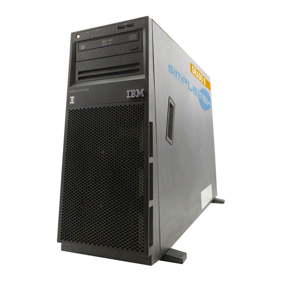
Page 19: Chapter 1. The Ibm System X3300 M4 Type 7382 Server
IBM Business Partners must also complete the steps in “Instructions for IBM Business Partners” on page 28. The IBM System x3300 M4 Type 7382 is a self-contained, entry level, tower-optimized, dual processor, 4U tower (optional rack mounted), server system. - Page 20 If firmware and documentation updates are available, you can download them from the IBM website. The server might have features that are not described in the documentation that comes with the server, and the documentation might be updated occasionally to include information about those features, or technical updates might be available to provide additional information that is not included in the server documentation.
-
Page 21: The Ibm Documentation Cd
You can download an IBM ServerGuide Setup and Installation CD to help you configure the hardware, install device drivers, and install the operating system. For a list of supported optional devices for the server, see http://www.ibm.com/ systems/info/x86servers/serverproven/compat/us/. See the Rack Installation Instructions document on the IBM System x Documentation CD for complete rack installation and removal instructions. -
Page 22: Related Documentation
IBM Warranty Information: This document is in printed format and comes with the server. It contains warranty terms and a pointer to the IBM Statement of Limited Warranty on the IBM website. v Important Notices: This document is in printed format and comes with the server. -
Page 23: Notices And Statements In This Document
These updates are available from the IBM website. To check for updates, go to http://www.ibm.com/supportportal/. Notices and statements in this document The caution and danger statements in this document are also in the multilingual Safety Information document, which is on the IBM System x Documentation CD. -
Page 24: Server Features And Specifications
– Multi-Burner (Rambo) v The server comes standard with two speed-controlled fans for one-microprocessor configuration (including one redundant fan) v Supports up to four fans with two microprocessors installed (including one redundant fan) System x3300 M4 Type 7382: Installation and Service Guide... - Page 25 One PCI-X Slot (optional): Particulate contamination. Note: 64-bit/133MHz 1. None support graphic card 2. The maximum PCIe card is up to 3 when two microprocessors installed for 550-watt ac. – 750-watt ac Chapter 1. The IBM System x3300 M4 Type 7382 server...
- Page 26 2. When more than 2 PCI-e adapters have been installed on the system, the fan (P/N: 00D2593) must be populated separately. Optional redundant fan (P/N: 00D2593) Attention: 16 GB 1.5V / 32 GB 1.35V DIMMs are installed, fan 1 must also be populated. System x3300 M4 Type 7382: Installation and Service Guide...
-
Page 27: What Your Server Offers
IBM Systems running in their environment with their applications. For more information, including the required levels of IBM Systems Director and Active Energy Manager, see the IBM Systems Director documentation on the IBM Systems Director DVD, or see http://www- 03.ibm.com/systems/software/director/aem/index.html. - Page 28 ServerGuide Setup and Installation CD” on page 114. v IBM Systems Director CD IBM Systems Director is the platform management backbone to achieve Smarter Computing. An integral component of the IBM Smarter Systems portfolio, IBM Systems Director enables integration with Tivoli, and third party management platforms, providing the building block for integrated services management.
- Page 29 The server comes with the Service Advisor feature that can collect data about the system when a the system detects a fault and sends that data to IBM Service for problem determination. It also includes the call home feature that automatically calls IBM Service when a problem occurs.
- Page 30 Hypervisor is virtualization software that enables multiple operating systems to run on a host system at the same time. See “Using the embedded hypervisor” on page 124 for additional information. System x3300 M4 Type 7382: Installation and Service Guide...
-
Page 31: Reliability, Availability, And Serviceability
Redundant network interface card (NIC) support v Remind button to temporarily turn off the system-error LED on the optional advanced operator information panel v Remote system problem-determination support v ROM-based diagnostics v ROM checksums Chapter 1. The IBM System x3300 M4 Type 7382 server... -
Page 32: Ibm Systems Director
A set of common tasks that are included with IBM Systems Director provides many of the core capabilities that are required for basic management, which means instant out-of-the-box business value. -
Page 33: The Updatexpress System Pack Installer
Updating installed plug-ins to add new features and functions to the base capabilities v Managing the life cycles of virtual resources For more information about IBM Systems Director, see the IBM Systems Director Information Center at http://publib.boulder.ibm.com/eserver/swic.html, and the Systems Management web page athttp://www-03.ibm.com/systems/x/solutions/ management/index.html , which presents an overview of IBM Systems... - Page 34 When this LED is lit, it indicates that the drive has failed. If an optional IBM ServeRAID controller is installed in the server, when this LED is flashing slowly (one flash per second), it indicates that the drive is being rebuilt.
-
Page 35: Operator Information Panel
System-locator LED: Use this blue LED to visually locate the server among other servers. You can use IBM Systems Director to light this LED remotely. This LED is controlled by the IMM. When you light the system-locator LED, the LED will blink and it will continue to blink until you turn it off. -
Page 36: Rear View
It allows you to blue screen the server and take a memory dump (use this button only when directed by the IBM service support). You might have to use a pen or the end of a straightened paper clip to press the button. - Page 37 See “Installing an adapter” on page 79 for information about adapters that this riser card support. Note: It has PCI-X capability by using PCI-e to PCI-X converter kit of IBM System x3500 M4 Type 7383. v Power connector: Connect the power cord to this connector.
- Page 38 Ethernet connectors: Use either of these connectors to connect the server to a network. When you use the Ethernet 1 connector, the network can be shared with the IMM through a single network cable. System x3300 M4 Type 7382: Installation and Service Guide...
-
Page 39: Power-Supply Leds
LEDs and the power-on LED on the operator information panel and suggested actions to correct the detected problems. Power-supply LEDs Error (!) Description Action Notes Normal operation Chapter 1. The IBM System x3300 M4 Type 7382 server... - Page 40 3. For hot-swap power-supply systems, follow actions listed in “Power problems” on page 289 and“Solving power problems” on page 296. Faulty Replace the power supply. power-supply Faulty Replace the power supply. power-supply System x3300 M4 Type 7382: Installation and Service Guide...
-
Page 41: System Pulse Leds
The amount of memory that is reserved for system resources depends on the operating system, the configuration of the server, and the configured PCI options. Chapter 1. The IBM System x3300 M4 Type 7382 server... -
Page 42: Turning Off The Server
2. Ethernet 1 connector supports Wake on LAN feature. 3. When you turn on the server with external graphical adapters installed, the IBM logo displays on the screen after approximately 3 minutes. This is normal operation while the system loads. - Page 43 The integrated management module II (IMM2) can turn off the server as an automatic response to a critical system failure. v The server turns off when the left-side cover is opened. Chapter 1. The IBM System x3300 M4 Type 7382 server...
- Page 44 System x3300 M4 Type 7382: Installation and Service Guide...
-
Page 45: Chapter 2. Installing Optional Devices
4. Use the best practices to apply current firmware and device-driver updates for the server and optional devices. To download the IBM System x Firmware Update Best Practices document, go to http://www.ibm.com/support/entry/portal/ docdisplay?brand=50000020&lndocid=MIGR-5082923. -
Page 46: Installing Optional Hardware Devices In The Server
3. Shut down and restart the server multiple times to ensure that the server is correctly configured and functions correctly with the newly installed devices. 4. Save the DSA log as a file and send it to IBM. For information about transferring data and logs, see http://publib.boulder.ibm.com/infocenter/ toolsctr/v1r0/index.jsp?topic=/dsa/dsa_main.html. -
Page 47: Server Components
Server components The following illustration shows the major components in the server. The illustrations in this document might differ slightly from your hardware. System-board internal connectors The following illustration shows the internal connectors on the system board. The following illustration shows the internal connectors on the microprocessor 2 expansion board. -
Page 48: System-Board External Connectors
System-board external connectors The following illustration shows the external input/output connectors on the system board. System x3300 M4 Type 7382: Installation and Service Guide... -
Page 49: System-Board Switches And Jumpers
System-board switches and jumpers The following illustration shows the jumper locations. Note: If there is a clear protective sticker on the top of the switch blocks, you must remove and discard it to access the switches. The following table describes the jumper on the system board. Table 4. - Page 50 RTMM FLASH Default off SW2-3 POWER_PERMISSION_N Force power permission (default off when F/W is ready) SW2-4 BYPASS_IMM_RESET_CONTROL_N Default off IMM_SPI_EN IMM_SPI_HALF_ROM_EN_N To allow override of the boot half (Default: jumper open) System x3300 M4 Type 7382: Installation and Service Guide...
-
Page 51: System-Board Leds
Table 4. System board jumpers (continued) Jumper number Jumper name Jumper setting Note: 1. If no jumper is present, the server responds as if the pins are set to 1 and 2. 2. Changing the position of the UEFI boot recovery jumper from pins 1 and 2 to pins 2 and 3 before the server is turned on alters which flash ROM page is loaded. - Page 52 The following illustration shows the light-emitting diodes (LEDs) on the microprocessor 2 expansion board. System x3300 M4 Type 7382: Installation and Service Guide...
-
Page 53: Hard Disk Drive Backplane Connectors
Hard Disk Drive Backplane Connectors The following illustrations show the connectors on the 2.5-inch and 3.5-inch hard disk drive backplanes and the backplane assembly. 1. Connectors on the hot-swap 3.5-inch hard disk drive backplane: 2. Connectors on the simple-swap 3.5-inch hard disk drive backplane: 3. -
Page 54: Installation Guidelines
Preboot diagnostic programs” on page 153 for information about how to run diagnostics. v Observe good housekeeping in the area where you are working. Place removed covers and other parts in a safe place. System x3300 M4 Type 7382: Installation and Service Guide... - Page 55 When you are finished working on the server, reinstall all safety shields, guards, labels, and ground wires. v For a list of supported optional devices for the server, see http:// www.ibm.com/servers/eserver/serverproven/compat/us/ Chapter 2. Installing optional devices...
-
Page 56: System Reliability Guidelines
Remove items from your shirt pocket, such as pens and pencils, that could fall into the server as you lean over it. v Avoid dropping any metallic objects, such as paper clips, hairpins, and screws, into the server. System x3300 M4 Type 7382: Installation and Service Guide... -
Page 57: Handling Static-Sensitive Devices
Handling static-sensitive devices Attention: Static electricity can damage the server and other electronic devices. To avoid damage, keep static-sensitive devices in their static-protective packages until you are ready to install them. To reduce the possibility of damage from electrostatic discharge, observe the following precautions: v Limit your movement. -
Page 58: Removing The Bezel
4. Open the bezel from the release point on the left edge of the bezel, and remove the bezel away from the server. System x3300 M4 Type 7382: Installation and Service Guide... -
Page 59: Removing The Air Baffle
Removing the air baffle To remove the air baffle, complete the following steps: 1. Read the safety information that begins in “Safety” on page vii and “Installation guidelines” on page 36. 2. Turn off the server (see “Turning off the server” on page 24) and all attached peripheral devices. -
Page 60: Removing The Fan Assembly
7. Press the fan release latch to slightly move the fan assembly backward. (see step 1 and 2 of the following illustration) 8. Lift the fan out of the server. (see the 3 of the following illustration) System x3300 M4 Type 7382: Installation and Service Guide... -
Page 61: Removing The Rear Fan
Removing the rear fan To remove the rear fan, complete the following steps: 1. Read the safety information that begins in “Safety” on page vii and “Installation guidelines” on page 36. 2. Turn off the server (see “Turning off the server” on page 24) and all attached peripheral devices. -
Page 62: Installing A Simple-Swap Fan
1. When you install the second microprocessor, you must also install fan 3. The fan filler can only be removed when fan 3 is installed. Otherwise, the fan filler must be installed for proper cooling. System x3300 M4 Type 7382: Installation and Service Guide... - Page 63 2. You can order the one additional fan for redundant cooling. 3. When more than 2 PCI-e adapters have been installed on the system, it is necessary to follow the fan configuration instruction as the table below. Table 5. Fan configuration instruction Fans Conditions 2 and...
- Page 64 9. Connect the fan power cable on the system board. (see “Internal Cable Routing and Connectors” on page 47). If you have other devices to install or remove, do so now. Otherwise, go to “Completing the installation” on page 104. System x3300 M4 Type 7382: Installation and Service Guide...
-
Page 65: Internal Cable Routing And Connectors
Internal Cable Routing and Connectors The server uses cables to connect SATA attached, hot-swap SATA, hot-swap SAS and DVD drive devices to the power supply and to the system board. Review the following information before connecting power and signal cables to internal drives: v The drives that are preinstalled in the server come with power and signal cables attached. -
Page 66: Operator Information Panel Cable Connection
Operator Information Panel Cable Connection The following illustration shows the internal cable routing and connectors from the operator information panel to the system board. System x3300 M4 Type 7382: Installation and Service Guide... -
Page 67: Optical Dvd And Tape Drive Cable Connection
Optical DVD and Tape Drive Cable Connection You can install either USB or SATA tape drives in the server. The following illustration shows the internal cable routing and connectors for the USB tape drives. It also shows the internal power cable for the optical drives. Hard Disk Drive Cable Connection Review the following information before connecting power and signal cables to internal drives:... - Page 68 ServeRAID adapter. Review the following information before connecting cables to the backplanes: 1. For server models with eight 2.5-inch hot-swap hard disk drives with the redundant power supply: System x3300 M4 Type 7382: Installation and Service Guide...
- Page 69 2. For server models with eight 2.5-inch hot-swap hard disk drives with the redundant power supply and the serveRAID adapter: 3. For server models with sixteen 2.5-inch hot-swap hard disk drives with the redundant power supply: Chapter 2. Installing optional devices...
- Page 70 4. For server models with sixteen 2.5-inch hot-swap hard disk drives with the redundant power supply and the serveRAID adapter: System x3300 M4 Type 7382: Installation and Service Guide...
- Page 71 5. For server models with four 3.5-inch hot-swap hard disk drives with the fixed power supply: Chapter 2. Installing optional devices...
- Page 72 7. For server models with eight 3.5-inch hot-swap hard disk drives with the fixed power supply: Note: It is necessary to use one 2*8 pins to 2*7 pins power cable for these server models come with a fixed power supply. System x3300 M4 Type 7382: Installation and Service Guide...
- Page 73 8. For server models with eight 3.5-inch hot-swap hard disk drives with the fixed power supply and the serveRAID adapter: Note: It is necessary to use one 2*8 pins to 2*7 pins power cable for these server models come with a fixed power supply. 9.
- Page 74 11. For server models with eight 3.5-inch hot-swap hard disk drives with the redundant power supply: Note: It is necessary to use two 2*8 pins to 2*7 pins power cables for these server models come with a redundant power supply. System x3300 M4 Type 7382: Installation and Service Guide...
- Page 75 12. For server models with eight 3.5-inch hot-swap hard disk drives with the redundant power supply and the ServeRAID adapter: Note: It is necessary to use two 2*8 pins to 2*7 pins power cables for these server models come with a redundant power supply. 13.
- Page 76 15. For server models with eight 3.5-inch simple-swap hard disk drives with the fixed power supply: Note: It is necessary to use one 2*7 pins to 2*8 pins power cable for these server models come with a fixed power supply. System x3300 M4 Type 7382: Installation and Service Guide...
- Page 77 16. For server models with eight 3.5-inch simple-swap hard disk drive with the fixed power supply and the ServeRAID adaptery: Note: It is necessary to use one 2*7 pins to 2*8 pins power cable for these server models come with a fixed power supply. 17.
- Page 78 18. For server models with four 3.5-inch simple-swap hard disk drives with the redundant power supply with the serveRAID adapter: 19. For server models with eight 3.5-inch simple-swap hard disk drives with the redundant power supply: System x3300 M4 Type 7382: Installation and Service Guide...
-
Page 79: Fan Power Cable Connection
20. For server models with eight 3.5-inch simple-swap hard disk drives with the redundant power supply with the serveRAID adapter: Fan Power Cable Connection The following illustration shows the internal cable routing and connectors from the fan assembly to the system board. Chapter 2. -
Page 80: Installing A Memory Module
16 = x16 organization - wwwww is the DIMM bandwidth, in MBps 8500 = 8.53 GBps (DDR3-1066 SDRAMs, 8-byte primary data bus) 10600 = 10.66 GBps (DDR3-1333 SDRAMs, 8-byte primary data bus) System x3300 M4 Type 7382: Installation and Service Guide... - Page 81 12800 = 12.80 GBps (DDR3-1600 SDRAMs, 8-byte primary data bus) 14900 = 14.93 GBps (DDR3-1866 SDRAMs, 8 byte primary data bus) 17000 = 17.06 GBps (DDR3-2133 SDRAMs, 8 byte primary data bus) - m is the DIMM type E = Unbuffered DIMM (UDIMM) with ECC (x72-bit module data bus) R = Registered DIMM (RDIMM) U = Unbuffered DIMM with no ECC (x64-bit primary data bus) - aa is the DDR3 SDRAM CAS latency, in clocks at maximum operating...
- Page 82 The spare rank must have identical or larger memory capacity than all the other ranks (sparing source ranks) on the same channel. After sparing, the sparing source rank will be lost. System x3300 M4 Type 7382: Installation and Service Guide...
- Page 83 – DIMMs must be installed in sets of three. The DIMMs in each set must be the same size and type. – The following table lists the DIMM installation sequence for rank sparing mode when one or two microprocessors is installed in the server: Table 10.
- Page 84 39). 5. Open the retaining clip on each end of the DIMM connector. Attention: To avoid breaking the retaining clips or damaging the DIMM connectors, open and close the clips gently. System x3300 M4 Type 7382: Installation and Service Guide...
-
Page 85: Installing Drives
6. Touch the static-protective package that contains the DIMM to any unpainted metal surface on the outside of the server. Then, remove the DIMM from the package. 7. Turn the DIMM so that the DIMM keys align correctly with the connector. 8. - Page 86 The server with sixteen 2.5-inch hard disk drives: v The server with four 3.5-inch hard disk drives: System x3300 M4 Type 7382: Installation and Service Guide...
- Page 87 The following notes describe the type of drives that the server supports and other information that you must consider when you install a drive. To confirm that the server supports the drive that you are installing, see http://www.ibm.com/ systems/info/x86servers/serverproven/compat/us/. v Locate the documentation that comes with the drive and follow those instructions in addition to the instructions in this chapter.
-
Page 88: Installing A 2.5-Inch Hot-Swap Hard Disk Drive
3. Open the bezel (see “Removing the bezel” on page 331) 4. Remove the filler panel, if one is present. System x3300 M4 Type 7382: Installation and Service Guide... - Page 89 If the server is configured for RAID operation through an optional ServeRAID adapter, you might have to re-configure your disk arrays after you install hard disk drives. See the ServeRAID documentation on the IBM ServeRAID Support CD for additional information about RAID operation and complete instructions for using ServeRAID Manager 8.
-
Page 90: Installing A 3.5-Inch Hot-Swap Hard Disk Drive
7. Align the drive assembly with the guide rails in the bay; then, carefully slide the drive assembly into the drive bay until the drive snaps into place. System x3300 M4 Type 7382: Installation and Service Guide... -
Page 91: Installing A 3.5-Inch Simple-Swap Hard Disk Drive
4, “Troubleshooting,” on page 139 for more information. Note: You might have to reconfigure the disk arrays after you install hard disk drives. See the RAID documentation on the IBM website at http://www.ibm.com/systems/support/ for information about RAID adapters. -
Page 92: Installing An Optical Cd/Dvd Drive
You have removed the blue optical drive rails from the side of the old drive and have them available for installation on the new drive. Note: If you are installing a drive that contains a laser, observe the following safety precautions. Statement 3 System x3300 M4 Type 7382: Installation and Service Guide... - Page 93 CAUTION: When laser products (such as CD-ROMs, DVD drives, fiber optic devices, or transmitters) are installed, note the following: v Do not remove the covers. Removing the covers of the laser product could result in exposure to hazardous laser radiation. There are no serviceable parts inside the device.
-
Page 94: Installing An Optional Tape Drive
9. Align the rails on the tape drive with the guides in the drive bay; then, slide the tape drive into the drive bay until the rails click into place. System x3300 M4 Type 7382: Installation and Service Guide... -
Page 95: Installing A Pci-X Riser-Card Assembly
10. Connect power and signal cables to the drive and the connectors on the system board (see “Internal Cable Routing and Connectors” on page 47) If you have other devices to install or remove, do so now. Otherwise, go to “Completing the installation”... - Page 96 Attention: Incomplete insertion might cause damage to the system board or the adapter. 10. Make sure the latch on the rear side of the PCI-X riser-card assembly is secured to the rear of the server chassis. System x3300 M4 Type 7382: Installation and Service Guide...
-
Page 97: Installing An Adapter
To confirm that the server supports the adapter that you are installing, see http://www.ibm.com/systems/info/x86servers/serverproven/compat/us/. v Locate the documentation that comes with the adapter and follow those instructions in addition to the instructions in this section. - Page 98 Option part CRU part Description number number QLogic 4Gb PCIe FC single-port HBA 39R6525 39R6526 QLogic 4Gb PCIe FC dual-port HBA 39R6527 39R6528 NetXtreme II 1000 express Ethernet adapter 39Y6066 39Y6070 System x3300 M4 Type 7382: Installation and Service Guide...
- Page 99 Emulex 8Gb FC dual-port HBA 42D0494 42D0500 QLogic 8Gb FC single-port HBA 42D0501 42D0507 QLogic 8Gb FC dual-port HBA 42D0510 42D0516 IBM 6Gb SAS HBA Controller 46M0907 68Y7354 Brocade 8Gb FC single-port HBA 46M6049 46M6061 Brocade 8Gb FC dual-port HBA 46M6050 46M6062...
- Page 100 9. Remove the PCI slot filler, if installed. Keep the filler in a safe place for potential future use. 10. Press the adapter firmly into the expansion slot. System x3300 M4 Type 7382: Installation and Service Guide...
- Page 101 Attention: v Incomplete insertion might cause damage to the system board or the adapter. v If you are installing or removing an adaptor into or from PCI slot 4, you have to press the release latch firstly as step 1 of the following illustration. Chapter 2.
- Page 102 8. Rotate the adapter-retention brackets on the PCI-X bracket to the open position. Note: Remove the expansion-slot cover if it is installed on the PCI-X bracket and save it for future use. System x3300 M4 Type 7382: Installation and Service Guide...
- Page 103 9. Remove the PCI slot filler, if installed. Keep the filler in a safe place for potential future use. 10. Press the adapter firmly into the expansion slot. Attention: Incomplete insertion might cause damage to the system board or the adapter. 11.
-
Page 104: Installing An Optional Serveraid Adapter Memory Module
11. Reconnect the external cables and power cords; then, turn on the attached devices and turn on the server. If you have other devices to install or remove, do so now. Otherwise, go to “Completing the installation” on page 104. System x3300 M4 Type 7382: Installation and Service Guide... -
Page 105: Installing A Raid Adapter Remote Battery In The Server
Installing a RAID adapter remote battery in the server When you install any RAID adapter that comes with batteries, it is sometimes necessary to install the batteries in another location in the server to prevent the batteries from overheating. To install a RAID adapter remote battery in the server, complete the following steps: 1. - Page 106 Align the battery cable connector with the slot on the battery holder. Place the battery into the battery holder and make sure that the battery holder engages the battery securely. System x3300 M4 Type 7382: Installation and Service Guide...
-
Page 107: Installing The Microprocessor 2 Expansion Board
Note: The positioning of the remote battery depends on the type of the remote batteries that you install. b. Connect the other end of the battery cable to the battery cable connector on the battery. c. Lower and press down on the retention clip until it snaps in place to hold the battery firmly in place. - Page 108 Fasten the thumbscrew on the side bracket. 9. Remove the cover on the microprocessor 2 expansion board connector and labels of CPU slot and PCI slot 1 on the system board. System x3300 M4 Type 7382: Installation and Service Guide...
- Page 109 10. Make sure the microprocessor 2 expansion board release levers are in the open position. 11. Align the holes on the microprocessor 2 expansion board to the guide pins on the system board. Install the microprocessor 2 expansion board on the system board.
-
Page 110: Installing A Microprocessor And Heat Sink
Intel Pentium microprocessor that came with the server. v See “Installing a microprocessor and heat sink” for notes and other information that you must consider when you install a microprocessor. System x3300 M4 Type 7382: Installation and Service Guide... - Page 111 v Be extremely careful, the pins on the socket are fragile. Any damage to the pins may require replacing the system board. v Use the microprocessor installation tool that came with the new microprocessor to remove the microprocessor from the server. Failure to use the microprocessor tool may cause damage to the pins on the socket.
- Page 112 See “Thermal grease” on page 96 for more information. b. Align the screws on the heat sink with the screw holes on the system board; then, place the heat sink on the microprocessor with the thermal-grease side down. System x3300 M4 Type 7382: Installation and Service Guide...
- Page 113 c. Press firmly on the captive screws and tighten them with a screwdriver. The follow illustration shows the sequence in tightening the screws, which is also shown on top of the heat sink. Begin with the screw labeled as "1", then "2", "3"...
-
Page 114: Thermal Grease
Note: If the grease is properly applied, approximately half of the grease will remain in the syringe. 6. Install the heat sink onto the microprocessor as described in “Installing a microprocessor and heat sink” on page 92. System x3300 M4 Type 7382: Installation and Service Guide... -
Page 115: Installing A Fixed Power Supply
To confirm that the server supports the power supply that you are installing, see http://www.ibm.com/systems/info/x86servers/serverproven/compat/us/. v Before replacing a power supply with one of a different wattage, the user may use the IBM Power Configurator utility to determine current system power consumption. For more information and to download the utility, go to http://www-03.ibm.com/systems/bladecenter/resources/powerconfig.html v The input voltage is 100 - 127 V ac or 200 - 240 V ac auto-sensing. - Page 116 11. If you have other devices to install or remove, do so now. Otherwise, go to “Completing the installation” on page 104. System x3300 M4 Type 7382: Installation and Service Guide...
-
Page 117: Installing The Power Paddle Card
Installing the power paddle card The power paddle card enables the redundancy power support. To install the power paddle card assembly, complete the following steps: 1. Read the safety information that begins in Safety and “Installation guidelines” on page 36. 2. -
Page 118: Installing A Hot-Swap Power Supply
Before installing an additional power supply or replace a power supply with one of a different wattage, the user may use the IBM Power Configurator utility to determine current system power consumption. For more information and to download the utility, go to http://www-03.ibm.com/systems/bladecenter/ resources/powerconfig.html... - Page 119 CAUTION: Never remove the cover on a power supply or any part that has the following label attached. Hazardous voltage, current, and energy levels are present inside any component that has this label attached. There are no serviceable parts inside these components.
- Page 120 9. If you are adding a power supply to the server, attach the redundant power information label that comes with this option on the server cover near the power supplies. System x3300 M4 Type 7382: Installation and Service Guide...
-
Page 121: Installing A Usb Embedded Hypervisor Flash Device
Installing a USB embedded hypervisor flash device To install a hypervisor flash device, complete the following steps: 1. Read the safety information that begins in Safety and “Installation guidelines” on page 36. 2. Turn off the server (see “Turning off the server” on page 24) and all attached peripheral devices. -
Page 122: Completing The Installation
8. Start the server. Confirm that is starts correctly and recognizes the newly installed devices, and make sure that no error LEDs are lit. 9. Complete the additional steps in “Instructions for IBM Business Partners” on page 28. System x3300 M4 Type 7382: Installation and Service Guide... -
Page 123: Installing The Fan Assembly
Installing the fan assembly To install the fan assembly, complete the following steps: 1. Read the safety information that begins in “Safety” on page vii and “Installation guidelines” on page 36. 2. Turn off the server (see “Turning off the server” on page 24) and all attached peripheral devices. -
Page 124: Installing The Rear Fan
(see step 1 in the following illustration). 9. Connect the rear fan power cable on the system board. (see “Internal Cable Routing and Connectors” on page 47). System x3300 M4 Type 7382: Installation and Service Guide... -
Page 125: Installing The Air Baffle
Installing the air baffle Note: When you install the second microprocessor, you must also install fan 2 and the air baffle that come with the second microprocessor upgrade kit. To install the air baffle, complete the following steps: 1. Read the safety information that begins in Safety and “Installation guidelines” on page 36. -
Page 126: Installing The Left-Side Cover
The following illustration shows the locations of the input and output connectors on the front of the server. The following illustration shows the locations of the input and output connectors on the rear of the server. System x3300 M4 Type 7382: Installation and Service Guide... -
Page 127: Updating The Server Configuration
You must turn off the server before you connect or disconnect cables. See the documentation that comes with any external devices for additional cabling instructions. It might be easier for you to route cables before you connect the devices to the server. Updating the server configuration When you start the server for the first time after you add or remove a device, you might receive a message that the configuration has changed. - Page 128 System x3300 M4 Type 7382: Installation and Service Guide...
-
Page 129: Chapter 3. Configuration Information And Instructions
The firmware for the server is periodically updated and is available for download on the IBM wb site. To check for the latest level of firmware, such as the UEFI firmware, vital product data (VPD) code, device drivers, and integrated management module (IMM) firmware, go to http://www.ibm.com/support/... -
Page 130: Configuring Uefi Compatible Devices
For information about using the IMM, see “Using the integrated management module II” on page 123 and the Integrated Management Module User's Guide at http://www.ibm.com/systems/support/ supportsite.wss/docdisplay?lndocid=MIGR-5079770&brandind=5000008. System x3300 M4 Type 7382: Installation and Service Guide... - Page 131 UEFI settings from the command line without the need to restart the server to access the Setup utility. For more information about using this program, see “IBM Advanced Settings Utility program” on page 131. Chapter 3. Configuration information and instructions...
-
Page 132: Using The Serverguide Setup And Installation Cd
To download the free image. click IBM Service and Support Site. Note: Changes are made periodically to the IBM web site. The actual procedure might vary slightly from what is described in this document. The ServerGuide program requires a supported IBM server with an enabled startable (bootable) CD drive. -
Page 133: Setup And Configuration Overview
When you use the ServerGuide Setup and Installation CD, you do not need setup diskettes. You can use the CD to configure any supported IBM server model. The setup program provides a list of tasks that are required to set up your server model. -
Page 134: Starting The Setup Utility
Setup utility menu choices The following choices are on the Setup utility main menu for the UEFI. Depending on the version of the IBM System x Server Firmware (server firmware), some menu choices might differ slightly from these descriptions. For more information on UEFI-compliant firmware, go to http://www-947.ibm.com/systems/support/... - Page 135 configured, and the operating system will not be able to detect it (this is equivalent to disconnecting the device). – Power Select this choice to view or change power capping to control consumption, processors, and performance states. - Active Energy Manager Select this choice to enable or disable power capping.
- Page 136 Select this choice to view or set legacy support. - Force Legacy Video on Boot Select this choice to force INT video support, if the operating system does not support UEFI video output standards. - Rehook INT 19h System x3300 M4 Type 7382: Installation and Service Guide...
- Page 137 Select this choice to enable or disable devices from taking control of the boot process. The default is Disable. - Legacy Thunk Support Select this choice to enable or disable UEFI to interact with PCI mass storage devices that are non-UEFI compliant. - Infinite Boot Retry Select this choice to enable or disable Infinitely retry the Legacy Boot order.
- Page 138 For more information, see “Administrator password” on page 122. v Save Settings Select this choice to save the changes that you have made in the settings. v Restore Settings System x3300 M4 Type 7382: Installation and Service Guide...
-
Page 139: Passwords
Select this choice to cancel the changes that you have made in the settings and restore the previous settings. v Load Default Settings Select this choice to cancel the changes that you have made in the settings and restore the factory settings. v Exit Setup Select this choice to exit from the Setup utility. -
Page 140: Using The Boot Manager Program
Use the backup copy of the server firmware until the primary copy is restored. After the primary copy is restored, turn off the server; then, move the UEFI Boot_backup jumper back to the primary position (pins 1 and 2). System x3300 M4 Type 7382: Installation and Service Guide... -
Page 141: The Updatexpress System Pack Installer
The UpdateXpress System Pack Installer detects supported and installed device drivers and firmware in the server and installs available updates. For additional information and to download the UpdateXpress System Pack Installer, go to the ToolsCenter for System x and BladeCenter at http://www-947.ibm.com/support/ entry/portal/docdisplay?lndocid=SERV-XPRESS#uxspinstall and click UpdateXpress System Pack Installer. -
Page 142: Using The Embedded Hypervisor
Using the embedded hypervisor The VMware ESXi embedded hypervisor software is available on the optional IBM USB flash device with embedded hypervisor. The USB flash device can be installed in the USB connector near PCI-e slot 1 on the system board. Hypervisor is virtualization software that enables multiple operating systems to run on a host system at the same time. - Page 143 To start using the embedded hypervisor functions, you must add the USB flash device to the startup sequence in the Setup utility. To add the USB flash device to the startup sequence, complete the following steps: 1. Turn on the server. Note: Approximately 1 to 3 minutes after the server is connected to ac power, the power-control button becomes active.
-
Page 144: Using The Remote Presence And Blue-Screen Capture Features
For more information on Features on Demand (FoD), including instructions for automating the activation and installation of the activation key by using IBM ToolsCenter or IBM Director, see the IBM System x Features on Demand User's Guide athttps://www-304.ibm.com/systems/x/fod/index.wss under the Help section. -
Page 145: Logging On To The Web Interface
For more information on Features on Demand (FoD), including instructions for automating the activation and installation of the activation key by using IBM ToolsCenter or IBM Director, see the IBM System x Features on Demand User's Guide at https://www- 304.ibm.com/systems/x/fod/index.wss under the Help section. -
Page 146: Configuring Raid Arrays
2. For more information about Configuration and Options Guide (COG), see http://www-947.ibm.com/support/entry/portal/docdisplay?lndocid=SCOD- 3ZVQ5W&brandind=5000019. 3. For further details on creating a software RAID array of hard disk drives, please see the ServeRAID C105 documentation at http://www-947.ibm.com/ support/entry/portal/docdisplay?lndocid=SERV-RAID. System x3300 M4 Type 7382: Installation and Service Guide... -
Page 147: Starting The Lsi Configuration Utility Program
Starting the LSI Configuration Utility program Use these instructions to start the LSI Configuration Utility program. To start the LSI Configuration Utility program, complete the following steps: 1. Turn on the server, and make sure that the server is the owner of the keyboard, video, and mouse. - Page 148 For more information on Features on Demand (FoD), including instructions for automating the activation and installation of the activation key by using IBM ToolsCenter or IBM Systems Director, see the IBM Features on Demand User's Guide at https://www-304.ibm.com/systems/x/fod/index.wss under the Help section.
-
Page 149: Ibm Advanced Settings Utility Program
IBM Advanced Settings Utility program The IBM Advanced Settings Utility (ASU) program is an alternative to the Setup utility for modifying UEFI settings. Use the ASU program online or out of band to modify UEFI settings from the command line without the need to restart the system to access the Setup utility. -
Page 150: Updating The Universal Unique Identifier (Uuid)
UEFI-based server. The ASU is an online tool that supports several operating systems. Make sure that you download the version for your operating system. You can download the ASU from the IBM Web site. To download the ASU and update the UUID, complete the following steps. - Page 151 See the Advanced Settings Utility Users Guide for more details. You can access the ASU Users Guide from the IBM Web site. Note: Changes are made periodically to the IBM Web site. The actual procedure might vary slightly from what is described in this document.
- Page 152 You can also build a bootable media using the applications available through the Tools Center Web site at http://www.ibm.com/support/entry/portal/ docdisplay?brand=5000008&lndocid=TOOL-CENTER. From the IBM Tools Center page, scroll down for the available tools. 5. Restart the server. System x3300 M4 Type 7382: Installation and Service Guide...
-
Page 153: Updating The Dmi/Smbios Data
UEFI-based server. The ASU is an online tool that supports several operating systems. Make sure that you download the version for your operating system. You can download the ASU from the IBM Web site. To download the ASU and update the DMI, complete the following steps. - Page 154 IPMI driver be installed. Some operating systems have the IPMI driver installed by default. ASU provides the corresponding mapping layer. You can download the ASU from the IBM Web site. To download the Advanced Settings Utility Users Guide, complete the following steps.
- Page 155 SYSTEM_PROD_DATA.SysEncloseAssetTag <asset_tag> --host <imm_ip> v Bootable media: You can also build a bootable media using the applications available through the ToolsCenter Web site athttp://www.ibm.com/support/entry/portal/ docdisplay?brand=5000008&lndocid=TOOL-CENTER. From the IBM ToolsCenter page, scroll down for the available tools 5. Restart the server.
- Page 156 System x3300 M4 Type 7382: Installation and Service Guide...
-
Page 157: Chapter 4. Troubleshooting
The documentation that comes with your operating system and software also contains troubleshooting information. Diagnosing a problem Before you contact IBM or an approved warranty service provider, follow these procedures in the order in which they are presented to diagnose a problem with your server. - Page 158 UpdateXpress System Pack contains an integration-tested bundle of online firmware and device-driver updates for your server. In addition, you can use IBM ToolsCenter Bootable Media Creator to create bootable media that is suitable for applying firmware updates and running preboot diagnostics.
-
Page 159: Undocumented Problems
Problem determination information is available for many devices such as RAID and network adapters. For problems with operating systems or IBM software or devices, go to http://www.ibm.com/supportportal/ . 7. Check for troubleshooting procedures and RETAIN tips. Troubleshooting procedures and RETAIN tips document known problems and suggested solutions. -
Page 160: Service Bulletins
IBM updates the support web site with the latest tips and techniques that you can use to solve many problems. To find service bulletins that are available for the IBM System x3300 M4 server, go to http://www.ibm.com/supportportal/ and search for 7382 and retain. -
Page 161: Performing The Checkout Procedure
Check the power supply LEDs (see “Power-supply LEDs” on page 21). b. Turn off the server and all external devices. c. Check all internal and external devices for compatibility at http://www.ibm.com/systems/info/x86servers/serverproven/compat/us/. d. Check all cables and power cords. e. Set all display controls to the middle positions. -
Page 162: Diagnostic Tools
Module User's Guide at http://www.ibm.com/systems/support/supportsite.wss/ docdisplay?lndocid=MIGR-5079770&brandind=5000008. v IBM Dynamic System Analysis Two editions of IBM Dynamic System Analysis (DSA) are available for diagnosing problems, DSA Portable and DSA Preboot: – DSA Portable DSA Portable collect and analyze system information to aid in diagnosing server problems. - Page 163 (as the IPMI event log), the integrated management module (IMM) chassis-event log (as the ASM event log), and the operating-system event logs. You can send the DSA log as a file to IBM service (when requested by service) or view the information as a text file or HTML file.
-
Page 164: Power-Supply Leds
LEDs and the power-on LED on the operator information panel and suggested actions to correct the detected problems. Power-supply LEDs Error (!) Description Action Notes Normal operation System x3300 M4 Type 7382: Installation and Service Guide... - Page 165 Replace the power supply. power-supply Power-supply not Typically indicates a 1. Reseat the power supply. fully seated, faulty power-supply is not 2. Use the IBM Power system board, or fully seated. Configurator utility to faulty determine current system power-supply power consumption. For...
-
Page 166: Event Logs
(see “Viewing event logs without restarting the server” on page 149). For more information about DSA and DSA messages, see “DSA messages” on page 228 and “IBM Dynamic System Analysis” on page 151. For more information about viewing the logs or clearing the logs, see “Viewing event logs through the Setup utility”... -
Page 167: Viewing Event Logs Through The Setup Utility
If IPMItool is installed in the server, you can use it to view the system-event log. Most recent versions of the Linux operating system come with a current version of IPMItool. For an overview of IPMI, go to http://www.ibm.com/developerwork/ linux/blueprints/ and click Using Intelligent Platform Management Interface (IPMI) on IBM Linux platforms. - Page 168 Alternatively, you can restart the server and press F1 to start the Setup utility and view the POST event log or system-event log. For more information, see “Viewing event logs through the Setup utility” on page 149. System x3300 M4 Type 7382: Installation and Service Guide...
-
Page 169: Clearing The Error Logs
If POST detects a problem, an error message is sent to the POST event log, see “Event logs” on page 148 for more information. IBM Dynamic System Analysis IBM Dynamic System Analysis (DSA) collects and analyzes system information to aid in diagnosing server problems. DSA collects the following information about the server:... -
Page 170: Dsa Editions
It is provided in the flash memory on the server, or you can create a bootable media such as a CD, DVD, ISO, USB, or PXE using the IBM ToolsCenter Bootable Media Creator (BoMC). For more details, see the BoMC User Guide at http://www.ibm.com/support/entry/portal/... -
Page 171: Running The Dsa Preboot Diagnostic Programs
Running the DSA Preboot diagnostic programs Note: The DSA memory test might take up to 30 minutes to run. If the problem is not a memory problem, skip the memory test. To run the DSA Preboot diagnostic programs that is stored in integrated flash memory on the server, complete the following steps: 1. -
Page 172: Viewing The Test Log Results
IBM provide tools that can automatically collect and send data or call IBM service when an error is detected. These tools can help IBM service speed up the process of diagnosing problems. The following sections provide information about the call home tools. -
Page 173: Error Messages
If an action step is preceded by “(Trained technician only),” that step must be performed only by a trained technician. v Go to the IBM support website at http://www.ibm.com/supportportal/ to check for technical information, hints, tips, and new device drivers or to submit a request for information. - Page 174 If an action step is preceded by “(Trained technician only),” that step must be performed only by a trained technician. v Go to the IBM support website at http://www.ibm.com/supportportal/ to check for technical information, hints, tips, and new device drivers or to submit a request for information.
- Page 175 If an action step is preceded by “(Trained technician only),” that step must be performed only by a trained technician. v Go to the IBM support website at http://www.ibm.com/supportportal/ to check for technical information, hints, tips, and new device drivers or to submit a request for information.
- Page 176 If an action step is preceded by “(Trained technician only),” that step must be performed only by a trained technician. v Go to the IBM support website at http://www.ibm.com/supportportal/ to check for technical information, hints, tips, and new device drivers or to submit a request for information.
- Page 177 If an action step is preceded by “(Trained technician only),” that step must be performed only by a trained technician. v Go to the IBM support website at http://www.ibm.com/supportportal/ to check for technical information, hints, tips, and new device drivers or to submit a request for information.
- Page 178 If an action step is preceded by “(Trained technician only),” that step must be performed only by a trained technician. v Go to the IBM support website at http://www.ibm.com/supportportal/ to check for technical information, hints, tips, and new device drivers or to submit a request for information.
- Page 179 If an action step is preceded by “(Trained technician only),” that step must be performed only by a trained technician. v Go to the IBM support website at http://www.ibm.com/supportportal/ to check for technical information, hints, tips, and new device drivers or to submit a request for information.
- Page 180 If an action step is preceded by “(Trained technician only),” that step must be performed only by a trained technician. v Go to the IBM support website at http://www.ibm.com/supportportal/ to check for technical information, hints, tips, and new device drivers or to submit a request for information.
- Page 181 If an action step is preceded by “(Trained technician only),” that step must be performed only by a trained technician. v Go to the IBM support website at http://www.ibm.com/supportportal/ to check for technical information, hints, tips, and new device drivers or to submit a request for information.
- Page 182 If an action step is preceded by “(Trained technician only),” that step must be performed only by a trained technician. v Go to the IBM support website at http://www.ibm.com/supportportal/ to check for technical information, hints, tips, and new device drivers or to submit a request for information.
- Page 183 If an action step is preceded by “(Trained technician only),” that step must be performed only by a trained technician. v Go to the IBM support website at http://www.ibm.com/supportportal/ to check for technical information, hints, tips, and new device drivers or to submit a request for information.
- Page 184 If an action step is preceded by “(Trained technician only),” that step must be performed only by a trained technician. v Go to the IBM support website at http://www.ibm.com/supportportal/ to check for technical information, hints, tips, and new device drivers or to submit a request for information.
- Page 185 If an action step is preceded by “(Trained technician only),” that step must be performed only by a trained technician. v Go to the IBM support website at http://www.ibm.com/supportportal/ to check for technical information, hints, tips, and new device drivers or to submit a request for information.
- Page 186 If an action step is preceded by “(Trained technician only),” that step must be performed only by a trained technician. v Go to the IBM support website at http://www.ibm.com/supportportal/ to check for technical information, hints, tips, and new device drivers or to submit a request for information.
- Page 187 If an action step is preceded by “(Trained technician only),” that step must be performed only by a trained technician. v Go to the IBM support website at http://www.ibm.com/supportportal/ to check for technical information, hints, tips, and new device drivers or to submit a request for information.
- Page 188 If an action step is preceded by “(Trained technician only),” that step must be performed only by a trained technician. v Go to the IBM support website at http://www.ibm.com/supportportal/ to check for technical information, hints, tips, and new device drivers or to submit a request for information.
- Page 189 If an action step is preceded by “(Trained technician only),” that step must be performed only by a trained technician. v Go to the IBM support website at http://www.ibm.com/supportportal/ to check for technical information, hints, tips, and new device drivers or to submit a request for information.
- Page 190 If an action step is preceded by “(Trained technician only),” that step must be performed only by a trained technician. v Go to the IBM support website at http://www.ibm.com/supportportal/ to check for technical information, hints, tips, and new device drivers or to submit a request for information.
-
Page 191: Integrated Management Module Ii (Imm2) Error Messages
If an action step is preceded by “(Trained technician only),” that step must be performed only by a trained technician. v Go to the IBM support website at http://www.ibm.com/supportportal/ to check for technical information, hints, tips, and new device drivers or to submit a request for information. - Page 192 2. Check the server airflow. Make sure (upper critical) has has asserted. that nothing is blocking the air from asserted. (n = coming into or preventing the air microprocessor from exiting the server. number) System x3300 M4 Type 7382: Installation and Service Guide...
- Page 193 Table 18. IMM2 error messages (continued) v Follow the suggested actions in the order in which they are listed in the Action column until the problem is solved. v If an action step is preceded by “(Trained technician only),” that step must be performed only by a trained technician.
- Page 194 Card. 2. For the fixed power-supply systems, replace the power supply. 3. Replace System board (see “Removing the system board” on page 428 and “Replacing the system board” on page 430). System x3300 M4 Type 7382: Installation and Service Guide...
- Page 195 Table 18. IMM2 error messages (continued) v Follow the suggested actions in the order in which they are listed in the Action column until the problem is solved. v If an action step is preceded by “(Trained technician only),” that step must be performed only by a trained technician.
- Page 196 Info This message is for No action; information only. (Power Supply n) the use case when has been turned off. an implementation has detected a Power Unit that has been Disabled. System x3300 M4 Type 7382: Installation and Service Guide...
- Page 197 3. If both the power-on LED and the power-supply error LED are not lit: v Use IBM power configurator utility to determine current system power consumption. For more information and to download the uility, go to http://www-03.ibm.com/...
- Page 198 2. Replace power supply n. transitioned to non-recoverable non-recoverable from state from a less (n = power supply number) a less severe state. (n severe state. = power supply number) System x3300 M4 Type 7382: Installation and Service Guide...
- Page 199 If an action step is preceded by “(Trained technician only),” that step must be performed only by a trained technician. 80070608-0a01xxxx Sensor PS n 12V OC Error A sensor has 1. Use the IBM Power Configurator 80070608-0a02xxxx Fault has changed to utility to determine current system transitioned to non-recoverable power consumption.
- Page 200 Please refer to the CPU voltage UEFI diagnostic code in the "UEFI mismatch with the diagnostic code" section of the Info socket voltage. Center for the appropriate user response. System x3300 M4 Type 7382: Installation and Service Guide...
- Page 201 Table 18. IMM2 error messages (continued) v Follow the suggested actions in the order in which they are listed in the Action column until the problem is solved. v If an action step is preceded by “(Trained technician only),” that step must be performed only by a trained technician.
- Page 202 5. (Trained technician only) Replace microprocessor n (see “Removing a microprocessor and heat sink” on page 416 and “Replacing a microprocessor and heat sink” on page 418). (n = microprocessor number) System x3300 M4 Type 7382: Installation and Service Guide...
- Page 203 Table 18. IMM2 error messages (continued) v Follow the suggested actions in the order in which they are listed in the Action column until the problem is solved. v If an action step is preceded by “(Trained technician only),” that step must be performed only by a trained technician.
- Page 204 4. (Trained technician only) Replace microprocessor n (see “Removing a microprocessor and heat sink” on page 416 and “Replacing a microprocessor and heat sink” on page 418). (n = microprocessor number) System x3300 M4 Type 7382: Installation and Service Guide...
- Page 205 Table 18. IMM2 error messages (continued) v Follow the suggested actions in the order in which they are listed in the Action column until the problem is solved. v If an action step is preceded by “(Trained technician only),” that step must be performed only by a trained technician.
- Page 206 Please refer to the the usable Memory UEFI diagnostic code in the "UEFI is insufficient for diagnostic code" section of the Info operation. Center for the appropriate user response. System x3300 M4 Type 7382: Installation and Service Guide...
- Page 207 Table 18. IMM2 error messages (continued) v Follow the suggested actions in the order in which they are listed in the Action column until the problem is solved. v If an action step is preceded by “(Trained technician only),” that step must be performed only by a trained technician.
- Page 208 430). 6. (Trained technician only) Replace the affected microprocessor (see “Removing a microprocessor and heat sink” on page 416 and “Replacing a microprocessor and heat sink” on page 418). System x3300 M4 Type 7382: Installation and Service Guide...
- Page 209 If an action step is preceded by “(Trained technician only),” that step must be performed only by a trained technician. 806f010c-2581xxxx Memory Error A memory 1. Check the IBM support website for uncorrectable error uncorrectable error an applicable retain tip or firmware detected for One of has occurred.
- Page 210 430). 6. (Trained technician only) Replace the affected microprocessor (see “Removing a microprocessor and heat sink” on page 416 and “Replacing a microprocessor and heat sink” on page 418). System x3300 M4 Type 7382: Installation and Service Guide...
- Page 211 806f030c-2004xxxx number) wait 10 seconds before restarting the 806f030c-2005xxxx server. 806f030c-2006xxxx 1. Check the IBM support website for 806f030c-2007xxxx an applicable retain tip or firmware 806f030c-2008xxxx update that applies to this memory 806f030c-2009xxxx error.
- Page 212 If no memory fault is recorded in the logs and no DIMM connector error LED is lit, you can re-enable the DIMM through the Setup utility or the Advanced Settings Utility (ASU). System x3300 M4 Type 7382: Installation and Service Guide...
- Page 213 3. Check the IBM support website for an applicable retain tip or firmware update that applies to this memory event. If no memory fault is...
- Page 214 430). 6. (Trained technician only) Replace the affected microprocessor (see “Removing a microprocessor and heat sink” on page 416 and “Replacing a microprocessor and heat sink” on page 418). System x3300 M4 Type 7382: Installation and Service Guide...
- Page 215 If an action step is preceded by “(Trained technician only),” that step must be performed only by a trained technician. 806f050c-2581xxxx Memory Logging Error The memory 1. Check the IBM support website for Limit Reached for logging limit has an applicable retain tip or firmware One of the DIMMs. been reached.
- Page 216 806f070c-2003xxxx for DIMM n Status. has occurred. size, type, speed, and technology. 806f070c-2004xxxx (n = DIMM number) 806f070c-2005xxxx 806f070c-2006xxxx 806f070c-2007xxxx 806f070c-2008xxxx 806f070c-2009xxxx 806f070c-200axxxx 806f070c-200bxxxx 806f070c-200cxxxx System x3300 M4 Type 7382: Installation and Service Guide...
- Page 217 Table 18. IMM2 error messages (continued) v Follow the suggested actions in the order in which they are listed in the Action column until the problem is solved. v If an action step is preceded by “(Trained technician only),” that step must be performed only by a trained technician.
- Page 218 806f050d-0405xxxx 3. Replace the SAS cable. 806f050d-0406xxxx 806f050d-0407xxxx 4. Replace the RAID adapter. 5. Replace the hard disk drive that is indicated by a lit status LED. System x3300 M4 Type 7382: Installation and Service Guide...
- Page 219 Table 18. IMM2 error messages (continued) v Follow the suggested actions in the order in which they are listed in the Action column until the problem is solved. v If an action step is preceded by “(Trained technician only),” that step must be performed only by a trained technician.
- Page 220 “Replacing the system board” on page 430). 806f0023-2101xxxx Watchdog Timer Info This message is for No action; information only. expired for IPMI the use case when Watchdog. an implementation has detected a Watchdog Timer Expired. System x3300 M4 Type 7382: Installation and Service Guide...
- Page 221 4. Make sure that the adapter is supported. For a list of supported optional devices, see http://www.ibm.com/systems/ info/x86servers/serverproven/ compat/us/. 5. Replace the adapters. 6. Replace the riser cards. Chapter 4. Troubleshooting...
- Page 222 Please refer to the non-critical state. normal. UEFI diagnostic code in the "UEFI diagnostic code" section of the Info Center for the appropriate user response. System x3300 M4 Type 7382: Installation and Service Guide...
- Page 223 Table 18. IMM2 error messages (continued) v Follow the suggested actions in the order in which they are listed in the Action column until the problem is solved. v If an action step is preceded by “(Trained technician only),” that step must be performed only by a trained technician.
- Page 224 CPU 2 PECI. 2. Replace microprocessor n. (n = microprocessor number) 81030012-2301xxxx OS RealTime Mod Info OS RealTime Mod No action; information only. state has deasserted. state has deasserted. System x3300 M4 Type 7382: Installation and Service Guide...
- Page 225 Table 18. IMM2 error messages (continued) v Follow the suggested actions in the order in which they are listed in the Action column until the problem is solved. v If an action step is preceded by “(Trained technician only),” that step must be performed only by a trained technician.
- Page 226 4. Remove components one at a time, restarting the server each time, to see if the problem goes away. 5. If the problem remains, (trained technician) replace the system board. System x3300 M4 Type 7382: Installation and Service Guide...
- Page 227 Table 18. IMM2 error messages (continued) v Follow the suggested actions in the order in which they are listed in the Action column until the problem is solved. v If an action step is preceded by “(Trained technician only),” that step must be performed only by a trained technician.
- Page 228 5. If the problem remains, (trained technician) replace the system board. Web interface messages 40000001-00000000 IMM Network Info An IMM network No action; information only. Initialization has completed Complete. initialization. System x3300 M4 Type 7382: Installation and Service Guide...
- Page 229 Table 18. IMM2 error messages (continued) v Follow the suggested actions in the order in which they are listed in the Action column until the problem is solved. v If an action step is preceded by “(Trained technician only),” that step must be performed only by a trained technician.
- Page 230 The specified user No action; information only. gateway modified has changed the from [arg1] to [arg2] gateway address of by user [arg3]. the Integrated Management Module external network interface to the specified value. System x3300 M4 Type 7382: Installation and Service Guide...
- Page 231 Table 18. IMM2 error messages (continued) v Follow the suggested actions in the order in which they are listed in the Action column until the problem is solved. v If an action step is preceded by “(Trained technician only),” that step must be performed only by a trained technician.
- Page 232 DN=%2, IP@=%3, IMM IP address SN=%4, GW@=%5, and configuration. DNS1@=%6.(%1 = CIM_DNSProtocolEndpoint.Hostname; %2 = CIM_DNSProtocolEndpoint.DomainName; %3 = CIM_IPProtocolEndpoint.IPv4Address; %4 = CIM_IPProtocolEndpoint.SubnetMask; %5 = IP address, xxx.xxx.xxx.xxx; %6 = IP address, xxx.xxx.xxx.xxx) System x3300 M4 Type 7382: Installation and Service Guide...
- Page 233 Table 18. IMM2 error messages (continued) v Follow the suggested actions in the order in which they are listed in the Action column until the problem is solved. v If an action step is preceded by “(Trained technician only),” that step must be performed only by a trained technician.
- Page 234 If the device resorted to running is part of a cluster solution, verify that the backup image. the latest level of code is supported for the cluster solution before you update the code. System x3300 M4 Type 7382: Installation and Service Guide...
- Page 235 Table 18. IMM2 error messages (continued) v Follow the suggested actions in the order in which they are listed in the Action column until the problem is solved. v If an action step is preceded by “(Trained technician only),” that step must be performed only by a trained technician.
- Page 236 Try to update the firmware again. failed for user update a firmware %3.(%1 = component from CIM_ManagedElement.ElementName; the interface and %2 = Web or IP address has LegacyCLI; %3 = failed. user ID) System x3300 M4 Type 7382: Installation and Service Guide...
- Page 237 Table 18. IMM2 error messages (continued) v Follow the suggested actions in the order in which they are listed in the Action column until the problem is solved. v If an action step is preceded by “(Trained technician only),” that step must be performed only by a trained technician.
- Page 238 [arg2] by user port number. [arg3]. 4000003e-00000000 SSH port number Info A user has No action; information only. changed from [arg1] modified the SSH to [arg2] by user port number. [arg3]. System x3300 M4 Type 7382: Installation and Service Guide...
- Page 239 Table 18. IMM2 error messages (continued) v Follow the suggested actions in the order in which they are listed in the Action column until the problem is solved. v If an action step is preceded by “(Trained technician only),” that step must be performed only by a trained technician.
- Page 240 Contact=[arg3], Location=[arg4], Room=[arg5], RackID=[arg6], Rack U-position=[arg7]. 40000051-00000000 Server Power Off Info A user configured No action; information only. Delay set to [arg1] the Server Power by user [arg2]. Off Delay. System x3300 M4 Type 7382: Installation and Service Guide...
- Page 241 Table 18. IMM2 error messages (continued) v Follow the suggested actions in the order in which they are listed in the Action column until the problem is solved. v If an action step is preceded by “(Trained technician only),” that step must be performed only by a trained technician.
- Page 242 User [arg1] role set Info A user account role No action; information only. to [arg2]. assigned. 40000068-00000000 User [arg1] custom Info User account No action; information only. privileges set: [arg2]. priveleges assigned. System x3300 M4 Type 7382: Installation and Service Guide...
- Page 243 Table 18. IMM2 error messages (continued) v Follow the suggested actions in the order in which they are listed in the Action column until the problem is solved. v If an action step is preceded by “(Trained technician only),” that step must be performed only by a trained technician.
- Page 244 Power cap throttling Info Power cap No action; information only. occurred. throttling occurred. 40000080-00000000 Remote Control Info Remote Control No action; information only. session started by session started user [arg1] in [arg2] mode. System x3300 M4 Type 7382: Installation and Service Guide...
- Page 245 Table 18. IMM2 error messages (continued) v Follow the suggested actions in the order in which they are listed in the Action column until the problem is solved. v If an action step is preceded by “(Trained technician only),” that step must be performed only by a trained technician.
-
Page 246: Dsa Messages
The following table describes the messages that the diagnostic programs might generate and suggested actions to correct the detected problems. Follow the suggested actions in the order in which they are listed in the column. System x3300 M4 Type 7382: Installation and Service Guide... - Page 247 If an action step is preceded by “(Trained technician only),” that step must be performed only by a trained technician. v Go to the IBM support web site at http://www.ibm.com/supportportal/ to check for technical information, hints, tips, and new device drivers or to submit a request for information.
- Page 248 If an action step is preceded by “(Trained technician only),” that step must be performed only by a trained technician. v Go to the IBM support web site at http://www.ibm.com/supportportal/ to check for technical information, hints, tips, and new device drivers or to submit a request for information.
- Page 249 If an action step is preceded by “(Trained technician only),” that step must be performed only by a trained technician. v Go to the IBM support web site at http://www.ibm.com/supportportal/ to check for technical information, hints, tips, and new device drivers or to submit a request for information.
- Page 250 If an action step is preceded by “(Trained technician only),” that step must be performed only by a trained technician. v Go to the IBM support web site at http://www.ibm.com/supportportal/ to check for technical information, hints, tips, and new device drivers or to submit a request for information.
- Page 251 If an action step is preceded by “(Trained technician only),” that step must be performed only by a trained technician. v Go to the IBM support web site at http://www.ibm.com/supportportal/ to check for technical information, hints, tips, and new device drivers or to submit a request for information.
- Page 252 If an action step is preceded by “(Trained technician only),” that step must be performed only by a trained technician. v Go to the IBM support web site at http://www.ibm.com/supportportal/ to check for technical information, hints, tips, and new device drivers or to submit a request for information.
- Page 253 If an action step is preceded by “(Trained technician only),” that step must be performed only by a trained technician. v Go to the IBM support web site at http://www.ibm.com/supportportal/ to check for technical information, hints, tips, and new device drivers or to submit a request for information.
- Page 254 If an action step is preceded by “(Trained technician only),” that step must be performed only by a trained technician. v Go to the IBM support web site at http://www.ibm.com/supportportal/ to check for technical information, hints, tips, and new device drivers or to submit a request for information.
- Page 255 If an action step is preceded by “(Trained technician only),” that step must be performed only by a trained technician. v Go to the IBM support web site at http://www.ibm.com/supportportal/ to check for technical information, hints, tips, and new device drivers or to submit a request for information.
- Page 256 If an action step is preceded by “(Trained technician only),” that step must be performed only by a trained technician. v Go to the IBM support web site at http://www.ibm.com/supportportal/ to check for technical information, hints, tips, and new device drivers or to submit a request for information.
- Page 257 If an action step is preceded by “(Trained technician only),” that step must be performed only by a trained technician. v Go to the IBM support web site at http://www.ibm.com/supportportal/ to check for technical information, hints, tips, and new device drivers or to submit a request for information.
- Page 258 If an action step is preceded by “(Trained technician only),” that step must be performed only by a trained technician. v Go to the IBM support web site at http://www.ibm.com/supportportal/ to check for technical information, hints, tips, and new device drivers or to submit a request for information.
- Page 259 If an action step is preceded by “(Trained technician only),” that step must be performed only by a trained technician. v Go to the IBM support web site at http://www.ibm.com/supportportal/ to check for technical information, hints, tips, and new device drivers or to submit a request for information.
- Page 260 If an action step is preceded by “(Trained technician only),” that step must be performed only by a trained technician. v Go to the IBM support web site at http://www.ibm.com/supportportal/ to check for technical information, hints, tips, and new device drivers or to submit a request for information.
- Page 261 If an action step is preceded by “(Trained technician only),” that step must be performed only by a trained technician. v Go to the IBM support web site at http://www.ibm.com/supportportal/ to check for technical information, hints, tips, and new device drivers or to submit a request for information.
- Page 262 If an action step is preceded by “(Trained technician only),” that step must be performed only by a trained technician. v Go to the IBM support web site at http://www.ibm.com/supportportal/ to check for technical information, hints, tips, and new device drivers or to submit a request for information.
- Page 263 If an action step is preceded by “(Trained technician only),” that step must be performed only by a trained technician. v Go to the IBM support web site at http://www.ibm.com/supportportal/ to check for technical information, hints, tips, and new device drivers or to submit a request for information.
- Page 264 If an action step is preceded by “(Trained technician only),” that step must be performed only by a trained technician. v Go to the IBM support web site at http://www.ibm.com/supportportal/ to check for technical information, hints, tips, and new device drivers or to submit a request for information.
- Page 265 If an action step is preceded by “(Trained technician only),” that step must be performed only by a trained technician. v Go to the IBM support web site at http://www.ibm.com/supportportal/ to check for technical information, hints, tips, and new device drivers or to submit a request for information.
- Page 266 If an action step is preceded by “(Trained technician only),” that step must be performed only by a trained technician. v Go to the IBM support web site at http://www.ibm.com/supportportal/ to check for technical information, hints, tips, and new device drivers or to submit a request for information.
- Page 267 If an action step is preceded by “(Trained technician only),” that step must be performed only by a trained technician. v Go to the IBM support web site at http://www.ibm.com/supportportal/ to check for technical information, hints, tips, and new device drivers or to submit a request for information.
- Page 268 If an action step is preceded by “(Trained technician only),” that step must be performed only by a trained technician. v Go to the IBM support web site at http://www.ibm.com/supportportal/ to check for technical information, hints, tips, and new device drivers or to submit a request for information.
- Page 269 If an action step is preceded by “(Trained technician only),” that step must be performed only by a trained technician. v Go to the IBM support web site at http://www.ibm.com/supportportal/ to check for technical information, hints, tips, and new device drivers or to submit a request for information.
- Page 270 If an action step is preceded by “(Trained technician only),” that step must be performed only by a trained technician. v Go to the IBM support web site at http://www.ibm.com/supportportal/ to check for technical information, hints, tips, and new device drivers or to submit a request for information.
- Page 271 If an action step is preceded by “(Trained technician only),” that step must be performed only by a trained technician. v Go to the IBM support web site at http://www.ibm.com/supportportal/ to check for technical information, hints, tips, and new device drivers or to submit a request for information.
- Page 272 If an action step is preceded by “(Trained technician only),” that step must be performed only by a trained technician. v Go to the IBM support web site at http://www.ibm.com/supportportal/ to check for technical information, hints, tips, and new device drivers or to submit a request for information.
- Page 273 If an action step is preceded by “(Trained technician only),” that step must be performed only by a trained technician. v Go to the IBM support web site at http://www.ibm.com/supportportal/ to check for technical information, hints, tips, and new device drivers or to submit a request for information.
- Page 274 If an action step is preceded by “(Trained technician only),” that step must be performed only by a trained technician. v Go to the IBM support web site at http://www.ibm.com/supportportal/ to check for technical information, hints, tips, and new device drivers or to submit a request for information.
- Page 275 If an action step is preceded by “(Trained technician only),” that step must be performed only by a trained technician. v Go to the IBM support web site at http://www.ibm.com/supportportal/ to check for technical information, hints, tips, and new device drivers or to submit a request for information.
- Page 276 If an action step is preceded by “(Trained technician only),” that step must be performed only by a trained technician. v Go to the IBM support web site at http://www.ibm.com/supportportal/ to check for technical information, hints, tips, and new device drivers or to submit a request for information.
- Page 277 If an action step is preceded by “(Trained technician only),” that step must be performed only by a trained technician. v Go to the IBM support web site at http://www.ibm.com/supportportal/ to check for technical information, hints, tips, and new device drivers or to submit a request for information.
- Page 278 If an action step is preceded by “(Trained technician only),” that step must be performed only by a trained technician. v Go to the IBM support web site at http://www.ibm.com/supportportal/ to check for technical information, hints, tips, and new device drivers or to submit a request for information.
- Page 279 If an action step is preceded by “(Trained technician only),” that step must be performed only by a trained technician. v Go to the IBM support web site at http://www.ibm.com/supportportal/ to check for technical information, hints, tips, and new device drivers or to submit a request for information.
- Page 280 If an action step is preceded by “(Trained technician only),” that step must be performed only by a trained technician. v Go to the IBM support web site at http://www.ibm.com/supportportal/ to check for technical information, hints, tips, and new device drivers or to submit a request for information.
- Page 281 If an action step is preceded by “(Trained technician only),” that step must be performed only by a trained technician. v Go to the IBM support web site at http://www.ibm.com/supportportal/ to check for technical information, hints, tips, and new device drivers or to submit a request for information.
- Page 282 If an action step is preceded by “(Trained technician only),” that step must be performed only by a trained technician. v Go to the IBM support web site at http://www.ibm.com/supportportal/ to check for technical information, hints, tips, and new device drivers or to submit a request for information.
- Page 283 If an action step is preceded by “(Trained technician only),” that step must be performed only by a trained technician. v Go to the IBM support web site at http://www.ibm.com/supportportal/ to check for technical information, hints, tips, and new device drivers or to submit a request for information.
- Page 284 If an action step is preceded by “(Trained technician only),” that step must be performed only by a trained technician. v Go to the IBM support web site at http://www.ibm.com/supportportal/ to check for technical information, hints, tips, and new device drivers or to submit a request for information.
- Page 285 If an action step is preceded by “(Trained technician only),” that step must be performed only by a trained technician. v Go to the IBM support web site at http://www.ibm.com/supportportal/ to check for technical information, hints, tips, and new device drivers or to submit a request for information.
- Page 286 If an action step is preceded by “(Trained technician only),” that step must be performed only by a trained technician. v Go to the IBM support web site at http://www.ibm.com/supportportal/ to check for technical information, hints, tips, and new device drivers or to submit a request for information.
- Page 287 If an action step is preceded by “(Trained technician only),” that step must be performed only by a trained technician. v Go to the IBM support web site at http://www.ibm.com/supportportal/ to check for technical information, hints, tips, and new device drivers or to submit a request for information.
- Page 288 If an action step is preceded by “(Trained technician only),” that step must be performed only by a trained technician. v Go to the IBM support web site at http://www.ibm.com/supportportal/ to check for technical information, hints, tips, and new device drivers or to submit a request for information.
- Page 289 If an action step is preceded by “(Trained technician only),” that step must be performed only by a trained technician. v Go to the IBM support web site at http://www.ibm.com/supportportal/ to check for technical information, hints, tips, and new device drivers or to submit a request for information.
- Page 290 If an action step is preceded by “(Trained technician only),” that step must be performed only by a trained technician. v Go to the IBM support web site at http://www.ibm.com/supportportal/ to check for technical information, hints, tips, and new device drivers or to submit a request for information.
- Page 291 If an action step is preceded by “(Trained technician only),” that step must be performed only by a trained technician. v Go to the IBM support web site at http://www.ibm.com/supportportal/ to check for technical information, hints, tips, and new device drivers or to submit a request for information.
- Page 292 If an action step is preceded by “(Trained technician only),” that step must be performed only by a trained technician. v Go to the IBM support web site at http://www.ibm.com/supportportal/ to check for technical information, hints, tips, and new device drivers or to submit a request for information.
- Page 293 If an action step is preceded by “(Trained technician only),” that step must be performed only by a trained technician. v Go to the IBM support web site at http://www.ibm.com/supportportal/ to check for technical information, hints, tips, and new device drivers or to submit a request for information.
-
Page 294: Troubleshooting By Symptom
If an action step is preceded by “(Trained technician only),” that step must be performed only by a trained technician. v Go to the IBM support web site at http://www.ibm.com/supportportal/ to check for technical information, hints, tips, and new device drivers or to submit a request for information. -
Page 295: Cd/Dvd Drive Problems
Follow the suggested actions in the order in which they are listed in the Action column until the problem is solved. v See Chapter 5, “Parts listing, IBM System x3300 M4 Type 7382,” on page 303 to check if a component is a consumable, structural, or FRU part. -
Page 296: Hypervisor Problems
Follow the suggested actions in the order in which they are listed in the Action column until the problem is solved. v See Chapter 5, “Parts listing, IBM System x3300 M4 Type 7382,” on page 303 to check if a component is a consumable, structural, or FRU part. -
Page 297: Hard Disk Drive Problems
Follow the suggested actions in the order in which they are listed in the Action column until the problem is solved. v See Chapter 5, “Parts listing, IBM System x3300 M4 Type 7382,” on page 303 to check if a component is a consumable, structural, or FRU part. - Page 298 Follow the suggested actions in the order in which they are listed in the Action column until the problem is solved. v See Chapter 5, “Parts listing, IBM System x3300 M4 Type 7382,” on page 303 to check if a component is a consumable, structural, or FRU part.
-
Page 299: Intermittent Problems
Follow the suggested actions in the order in which they are listed in the Action column until the problem is solved. v See Chapter 5, “Parts listing, IBM System x3300 M4 Type 7382,” on page 303 to check if a component is a consumable, structural, or FRU part. -
Page 300: Keyboard, Mouse, Or Pointing-Device Problems
Follow the suggested actions in the order in which they are listed in the Action column until the problem is solved. v See Chapter 5, “Parts listing, IBM System x3300 M4 Type 7382,” on page 303 to check if a component is a consumable, structural, or FRU part. - Page 301 Follow the suggested actions in the order in which they are listed in the Action column until the problem is solved. v See Chapter 5, “Parts listing, IBM System x3300 M4 Type 7382,” on page 303 to check if a component is a consumable, structural, or FRU part.
-
Page 302: Memory Problems
Follow the suggested actions in the order in which they are listed in the Action column until the problem is solved. v See Chapter 5, “Parts listing, IBM System x3300 M4 Type 7382,” on page 303 to check if a component is a consumable, structural, or FRU part. -
Page 303: Microprocessor Problems
Follow the suggested actions in the order in which they are listed in the Action column until the problem is solved. v See Chapter 5, “Parts listing, IBM System x3300 M4 Type 7382,” on page 303 to check if a component is a consumable, structural, or FRU part. -
Page 304: Monitor And Video Problems
Follow the suggested actions in the order in which they are listed in the Action column until the problem is solved. v See Chapter 5, “Parts listing, IBM System x3300 M4 Type 7382,” on page 303 to check if a component is a consumable, structural, or FRU part. - Page 305 Follow the suggested actions in the order in which they are listed in the Action column until the problem is solved. v See Chapter 5, “Parts listing, IBM System x3300 M4 Type 7382,” on page 303 to check if a component is a consumable, structural, or FRU part.
-
Page 306: Optional-Device Problems
Follow the suggested actions in the order in which they are listed in the Action column until the problem is solved. v See Chapter 5, “Parts listing, IBM System x3300 M4 Type 7382,” on page 303 to check if a component is a consumable, structural, or FRU part. -
Page 307: Power Problems
Follow the suggested actions in the order in which they are listed in the Action column until the problem is solved. v See Chapter 5, “Parts listing, IBM System x3300 M4 Type 7382,” on page 303 to check if a component is a consumable, structural, or FRU part. - Page 308 Follow the suggested actions in the order in which they are listed in the Action column until the problem is solved. v See Chapter 5, “Parts listing, IBM System x3300 M4 Type 7382,” on page 303 to check if a component is a consumable, structural, or FRU part.
- Page 309 Follow the suggested actions in the order in which they are listed in the Action column until the problem is solved. v See Chapter 5, “Parts listing, IBM System x3300 M4 Type 7382,” on page 303 to check if a component is a consumable, structural, or FRU part.
- Page 310 Follow the suggested actions in the order in which they are listed in the Action column until the problem is solved. v See Chapter 5, “Parts listing, IBM System x3300 M4 Type 7382,” on page 303 to check if a component is a consumable, structural, or FRU part.
- Page 311 Follow the suggested actions in the order in which they are listed in the Action column until the problem is solved. v See Chapter 5, “Parts listing, IBM System x3300 M4 Type 7382,” on page 303 to check if a component is a consumable, structural, or FRU part.
-
Page 312: Serial-Device Problems
Follow the suggested actions in the order in which they are listed in the Action column until the problem is solved. v See Chapter 5, “Parts listing, IBM System x3300 M4 Type 7382,” on page 303 to check if a component is a consumable, structural, or FRU part. -
Page 313: Software Problems
Follow the suggested actions in the order in which they are listed in the Action column until the problem is solved. v See Chapter 5, “Parts listing, IBM System x3300 M4 Type 7382,” on page 303 to check if a component is a consumable, structural, or FRU part. -
Page 314: Universal Serial Bus (Usb) Port Problems
Follow the suggested actions in the order in which they are listed in the Action column until the problem is solved. v See Chapter 5, “Parts listing, IBM System x3300 M4 Type 7382,” on page 303 to check if a component is a consumable, structural, or FRU part. -
Page 315: Solving Ethernet Controller Problems
Table 20. Components associated with power rail error (continued) Pwr rail error in the IMM2 event log Components Pwr rail 3 error Microprocessor 2 Pwr rail 4 error Fan 4, and DIMMs 1 through 12 Pwr rail 5 error For the hot-swap power-supplie systems: Hard disk drives, hard disk drive backplane assembly, and optional DVD or Tape drive. -
Page 316: Solving Undetermined Problems
If you suspect a networking problem and the server passes all the system tests, suspect a network cabling problem that is external to the server. System x3300 M4 Type 7382: Installation and Service Guide... -
Page 317: Problem Determination Tips
Problem determination tips Because of the variety of hardware and software combinations that can encounter, use the following information to assist you in problem determination. The model number and serial number are located on the ID label on the front of the server as shown in the following illustration. -
Page 318: Recovering The Server Firmware
The flash memory of the server consists of a primary bank and a backup bank. You must maintain a bootable IBM System x Server Firmware (server firmware) image in the backup bank. If the server firmware in the primary bank becomes corrupted,... - Page 319 5. Reinstall the server cover; then, reconnect all power cords. 6. Restart the server. The power-on self-test (POST) starts. 7. Boot the server to an operating system that is supported by the IBM Flash UEFI Update package that you downloaded.
-
Page 320: Automated Boot Recovery (Abr)
2. Remove any devices that you added recently and restart the server. 3. If the problem remains, start the Setup utility, select Load Default Settings to restore the server factory settings, and select Save Settings. System x3300 M4 Type 7382: Installation and Service Guide... -
Page 321: Chapter 5. Parts Listing, Ibm System X3300 M4 Type 7382
Tier 1 customer replaceable unit (CRU): Replacement of Tier 1 CRUs is your responsibility. If IBM installs a Tier 1 CRU at your request, you will be charged for the installation. v Tier 2 customer replaceable unit: You may install a Tier 2 CRU yourself or request IBM to install it, at no additional charge, under the type of warranty service that is designated for your server. - Page 322 Hard disk drive, 3.5-inch simple-swap, 500 GB, 7.2 K, 6 81Y9803 Gbps SATA hard disk drive Hard disk drive, 3.5-inch simple-swap, 2 TB, 7.2 K, 6 81Y9811 Gbps SATA hard disk drive System x3300 M4 Type 7382: Installation and Service Guide...
- Page 323 Microprocessor, Intel Xeon E5-2403 4C 1.8GHz 10MB 90Y4744 cache 1066MHz 80W microprocessor Microprocessor, Intel Xeon E5-2470 8C 2.3GHz 20MB 90Y4736 cache 1600MHz 95W microprocessor Microprocessor, Intel Xeon E5-2450 8C 2.1GHz 20MB 90Y4738 cache 1600MHz 95W microprocessor Chapter 5. Parts listing, IBM System x3300 M4 Type 7382...
- Page 324 94Y8060 power, 460 watt fixed power supply unit 94Y8057 Kit, first 2.5-inch hot-swap kit 00D2817 Kit, tower to rack kit 68Y7213 Kit, 4U rack kit 68Y7226 Cable, SAS 680R cable 00D2814 System x3300 M4 Type 7382: Installation and Service Guide...
-
Page 325: Consumable And Structural Parts
33F8354 Battery, M5100 SERIES battery 81Y4491 Controller, ServeRAID M1115 SAS/SATA Controller 46C8928 Consumable and Structural parts Consumable and structural parts are not covered by the IBM Statement of Limited Warranty. Table 22. Structural parts, Type 7382 Index Description Part number... -
Page 326: Power Cords
To order a consumable or structural part, Go to http://www.ibm.com. If you need help with your order, call the toll-free number that is listed on the retail parts page, or contact your local IBM representative for assistance. Power cords For your safety, a power cord with a grounded attachment plug is provided to use with this product. - Page 327 Colombia, Costa Rica, Cuba, Dominican Republic, Ecuador, El Salvador, Guam, Guatemala, Haiti, Honduras, Jamaica, Mexico, Micronesia (Federal States of), Netherlands Antilles, Nicaragua, Panama, Peru, Philippines, Saudi Arabia, Thailand, Taiwan, United States of America, Venezuela Chapter 5. Parts listing, IBM System x3300 M4 Type 7382...
- Page 328 Micronesia (Federal States of), Netherlands Antilles, Nicaragua, Panama, Peru, Philippines, Saudi Arabia, Thailand, Taiwan, United States of America, Venezuela 39M5219 Korea (Democratic People's Republic of), Korea (Republic of) 39M5199 Japan 39M5226 India 39M5240 Brazil System x3300 M4 Type 7382: Installation and Service Guide...
-
Page 329: Chapter 6. Removing And Replacing Components
IBM to install it, at no additional charge, under the type of warranty service that is designated for your server. See Chapter 5, “Parts listing, IBM System x3300 M4 Type 7382,” on page 303 to determine whether a component is a consumable, structural, or FRU that must be replaced only by a trained service technician. - Page 330 When you are finished working on the server, reinstall all safety shields, guards, labels, and ground wires. System x3300 M4 Type 7382: Installation and Service Guide...
-
Page 331: System Reliability Guidelines
For a list of supported optional devices for the server, see http:// www.ibm.com/servers/eserver/serverproven/compat/us/ System reliability guidelines To help ensure proper system cooling and system reliability, make sure that the following requirements are met: v Each of the drive bays has a drive or a filler panel and electromagnetic compatibility (EMC) shield installed in it. -
Page 332: Handling Static-Sensitive Devices
If you replace any drives, remember which cable is attached to which drive. v When you route a cable, make sure that it does not block the airflow to the rear of the drives or over the microprocessor or DIMMs. System x3300 M4 Type 7382: Installation and Service Guide... -
Page 333: Power Cable Connection
Power Cable Connection The following illustration shows the fixed power cable routing. The following illustration shows the hot-swap power cable routing. Chapter 6. Removing and replacing components... -
Page 334: Operator Information Panel Cable Connection
You can install either USB or SATA tape drives in the server. The following illustration shows the internal cable routing and connectors for the USB tape drives. It also shows the internal power cable for the optical drives. System x3300 M4 Type 7382: Installation and Service Guide... -
Page 335: Hard Disk Drive Cable Connection
Hard Disk Drive Cable Connection Review the following information before connecting power and signal cables to internal drives: 1. Connectors on the hot-swap 3.5-inch hard disk drive backplane: 2. Connectors on the simple-swap 3.5-inch hard disk drive backplate: Chapter 6. Removing and replacing components... - Page 336 ServeRAID adapter. Review the following information before connecting cables to the backplanes: 1. For server models with eight 2.5-inch hot-swap hard disk drives with the redundant power supply: System x3300 M4 Type 7382: Installation and Service Guide...
- Page 337 2. For server models with eight 2.5-inch hot-swap hard disk drives with the redundant power supply and the serveRAID adapter: 3. For server models with sixteen 2.5-inch hot-swap hard disk drives with the redundant power supply: Chapter 6. Removing and replacing components...
- Page 338 4. For server models with sixteen 2.5-inch hot-swap hard disk drives with the redundant power supply and the serveRAID adapter: System x3300 M4 Type 7382: Installation and Service Guide...
- Page 339 5. For server models with four 3.5-inch hot-swap hard disk drives with the fixed power supply: Chapter 6. Removing and replacing components...
- Page 340 7. For server models with eight 3.5-inch hot-swap hard disk drives with the fixed power supply: Note: It is necessary to use one 2*8 pins to 2*7 pins power cable for these server models come with a fixed power supply. System x3300 M4 Type 7382: Installation and Service Guide...
- Page 341 8. For server models with eight 3.5-inch hot-swap hard disk drives with the fixed power supply and the serveRAID adapter: Note: It is necessary to use one 2*8 pins to 2*7 pins power cable for these server models come with a fixed power supply. 9.
- Page 342 11. For server models with eight 3.5-inch hot-swap hard disk drives with the redundant power supply: Note: It is necessary to use two 2*8 pins to 2*7 pins power cables for these server models come with a redundant power supply. System x3300 M4 Type 7382: Installation and Service Guide...
- Page 343 12. For server models with eight 3.5-inch hot-swap hard disk drives with the redundant power supply and the ServeRAID adapter: Note: It is necessary to use two 2*8 pins to 2*7 pins power cables for these server models come with a redundant power supply. 13.
- Page 344 15. For server models with eight 3.5-inch simple-swap hard disk drives with the fixed power supply: Note: It is necessary to use one 2*7 pins to 2*8 pins power cable for these server models come with a fixed power supply. System x3300 M4 Type 7382: Installation and Service Guide...
- Page 345 16. For server models with eight 3.5-inch simple-swap hard disk drive with the fixed power supply and the ServeRAID adaptery: Note: It is necessary to use one 2*7 pins to 2*8 pins power cable for these server models come with a fixed power supply. 17.
- Page 346 18. For server models with four 3.5-inch simple-swap hard disk drives with the redundant power supply with the serveRAID adapter: 19. For server models with eight 3.5-inch simple-swap hard disk drives with the redundant power supply: System x3300 M4 Type 7382: Installation and Service Guide...
-
Page 347: Fan Power Cable Connection
20. For server models with eight 3.5-inch simple-swap hard disk drives with the redundant power supply with the serveRAID adapter: Fan Power Cable Connection The following illustration shows the internal cable routing and connectors from the fan assembly to the system board. Chapter 6. -
Page 348: Removing And Replacing Components
IBM to install it, at no additional charge, under the type of warranty service that is designated for your server. See Chapter 5, “Parts listing, IBM System x3300 M4 Type 7382,” on page 303 to determine whether a component is a consumable, structural, or FRU that must be replaced only by a trained service technician. -
Page 349: Removing And Replacing Consumable And Structural Parts
Removing and replacing consumable and structural parts Replacement of consumable parts and structural parts is your responsibility. If IBM installs a consumable part or structural part at your request, you will be charged for the installation. The illustrations in this document might differ slightly from the hardware. -
Page 350: Replacing The Bezel
Attention: The server automatically powers off when the left-side cover is removed. To remove the left-side cover, complete the following steps: 1. Read the safety information that begins in “Safety” on page vii and “Installation guidelines” on page 36. System x3300 M4 Type 7382: Installation and Service Guide... -
Page 351: Installing The Left-Side Cover
2. Turn off the server (see “Turning off the server” on page 24) and all attached peripheral devices. Disconnect all power cords; then, disconnect all external cables as necessary to replace the device. 3. Carefully turn the server on its side so that it is lying flat, with the left-side cover facing up. -
Page 352: Replacing The Stabilizing Feet
In some cases, you might need a screwdriver to press in on the clips. 6. To reinstall the feet in the location, push the clips of the feet into the right place of the server. System x3300 M4 Type 7382: Installation and Service Guide... -
Page 353: Removing The Air Baffle
Removing the air baffle To remove the air baffle, complete the following steps: 1. Read the safety information that begins in “Safety” on page vii and “Installation guidelines” on page 36. 2. Turn off the server (see “Turning off the server” on page 24) and all attached peripheral devices. -
Page 354: Replacing The Air Baffle
6. Slide the air baffle down into the server until the tabs fit into the locating holes. If you have other devices to install or remove, do so now. Otherwise, go to “Completing the installation” on page 104. System x3300 M4 Type 7382: Installation and Service Guide... -
Page 355: Removing A Raid Adapter Remote Battery Holder
Removing a RAID adapter remote battery holder When you install any RAID adapter that comes with batteries, it is sometimes necessary to install the batteries in another location in the server to prevent the batteries from overheating. To install a RAID adapter remote battery in the server, complete the following steps: 1. -
Page 356: Replacing A Raid Adapter Remote Battery Holder
(It might be easier for you to route cables before you install the adapter.) 8. Align the battery holder with the guide pin to install the battery holder. System x3300 M4 Type 7382: Installation and Service Guide... -
Page 357: Removing And Replacing Tier 1 Crus
“Completing the installation” on page 104. Removing and replacing Tier 1 CRUs Replacement of Tier 1 CRUs is your responsibility. If IBM installs a Tier 1 CRU at your request, you will be charged for the installation. The illustrations in this document might differ slightly from your hardware. - Page 358 The server with sixteen 2.5-inch hard disk drives: v The server with four 3.5-inch hard disk drives: System x3300 M4 Type 7382: Installation and Service Guide...
- Page 359 The following notes describe the type of drives that the server supports and other information that you must consider when you install a drive. To confirm that the server supports the drive that you are installing, see http://www.ibm.com/ systems/info/x86servers/serverproven/compat/us/. v Locate the documentation that comes with the drive and follow those instructions in addition to the instructions in this chapter.
- Page 360 3. Open the bezel (see “Removing the bezel” on page 331) 4. Remove the filler panel, if one is present. System x3300 M4 Type 7382: Installation and Service Guide...
- Page 361 RAID configuration). v For a list of supported optional devices for the server, see http:// www.ibm.com/servers/eserver/serverproven/compat/us/ v Inspect the drive and drive bay for signs of damage. v Make sure that the drive is correctly installed in the drive bay.
- Page 362 7. Rotate the drive handle until the drive is seated in the hot-swap bay and the release latch clicks into place. Note: a. After you install the hard disk drive, check the disk drive status LEDs to verify that the hard disk drive is operating correctly. System x3300 M4 Type 7382: Installation and Service Guide...
- Page 363 If the server is configured for RAID operation through an optional ServeRAID adapter, you might have to re-configure your disk arrays after you install hard disk drives. See the ServeRAID documentation on the IBM ServeRAID Support CD for additional information about RAID operation and complete instructions for using ServeRAID Manager 8.
- Page 364 4, “Troubleshooting,” on page 139 for more information. Note: You might have to reconfigure the disk arrays after you install hard disk drives. See the RAID documentation on the IBM website at http://www.ibm.com/systems/support/ for information about RAID adapters.
- Page 365 4, “Troubleshooting,” on page 139 for more information. Note: You might have to re-configure the disk arrays after you install hard disk drives. See the RAID documentation on the IBM website at http://www.ibm.com/systems/support/ for information about RAID adapters.
- Page 366 4. Open the bezel (see “Removing the bezel” on page 331). 5. Move the release latch to open position and grasp the drive handle to pull the 3.5-inch simple swap drive out of the drive bay of the server. System x3300 M4 Type 7382: Installation and Service Guide...
- Page 367 6. Install the filler panel into the empty drive bay. If you have other devices to install or remove, do so now. Otherwise, go to “Completing the installation” on page 104 Replacing a 3.5-inch simple-swap hard disk drive: Before replacing a 3.5-inch simple-swap hard disk drive, read the following information: v Inspect the drive tray for signs of damage.
- Page 368 You have removed the blue optical drive rails from the side of the old drive and have them available for installation on the new drive. Note: If you are installing a drive that contains a laser, observe the following safety precautions. Statement 3 System x3300 M4 Type 7382: Installation and Service Guide...
- Page 369 CAUTION: When laser products (such as CD-ROMs, DVD drives, fiber optic devices, or transmitters) are installed, note the following: v Do not remove the covers. Removing the covers of the laser product could result in exposure to hazardous laser radiation. There are no serviceable parts inside the device.
- Page 370 You have removed the blue optical drive rails from the side of the old drive and have them available for installation on the new drive. Note: If you are installing a drive that contains a laser, observe the following safety precautions. Statement 3 System x3300 M4 Type 7382: Installation and Service Guide...
- Page 371 CAUTION: When laser products (such as CD-ROMs, DVD drives, fiber optic devices, or transmitters) are installed, note the following: v Do not remove the covers. Removing the covers of the laser product could result in exposure to hazardous laser radiation. There are no serviceable parts inside the device.
- Page 372 7. Remove the fan assembly (see “Removing the fan assembly” on page 42) 8. Pressing the drive rail on the side of the tape drive and grasp the front of tape drive out of the server. System x3300 M4 Type 7382: Installation and Service Guide...
- Page 373 9. Install the EMC shields to the tape drive bay. If you have other devices to install or remove, do so now. Otherwise, go to “Completing the installation” on page 104 Replacing an optional tape drive: To replace an optional full-height tape drive, complete the following steps: 1.
-
Page 374: Replacing A Sas/Sata Hdd Option
6. Remove the 2.5-inch hot-swap SAS/SATA hard disk drive backplane (see Replacing the hot-swap drive backplane You can install an IBM System x3300 M4 Hot-swap SAS/SATA 8 Pac HDD option in the server. See http://www.ibm.com/systems/info/x86servers/serverproven/ compat/us/ for a list of supported optional devices. To order a SAS/SATA 8 Pac HDD option, contact your IBM marketing representative or authorized reseller. - Page 375 3. Remove the bezel (see “Removing the bezel” on page 331 4. Remove the left-side cover (see “Removing the left-side cover” on page 39 5. Remove the fillers if necessary. 6. Install the 2.5-inch hard disk drive cage if necessary. Note: If you are upgrading the hard disk drive bays from 16 to 24 and the 2.5-inch hard disk drive cage is already installed.
-
Page 376: Removing An Adapter
6. Remove the fan assembly (see “Removing the fan assembly” on page 42). 7. Disconnect any cables from the adapter. 8. Press down the release latch from the rear of the server to move forward the adapter-retention brackets to the open position. System x3300 M4 Type 7382: Installation and Service Guide... - Page 377 9. Pull the adapter out of the adapter connector; then, lift the adapter out of the server. Chapter 6. Removing and replacing components...
- Page 378 11. Move the adapter-retention brackets back to the close position. 12. If you are instructed to return the adapter, follow all packaging instructions, and use any packaging materials for shipping that are supplied to you. System x3300 M4 Type 7382: Installation and Service Guide...
-
Page 379: Replacing An Adapter
To confirm that the server supports the adapter that you are installing, see http://www.ibm.com/systems/info/x86servers/serverproven/compat/us/. v Locate the documentation that comes with the adapter and follow those instructions in addition to the instructions in this section. - Page 380 To avoid this potential problem, always use an electrostatic-discharge wrist strap or other grounding system when working inside the server with the power on. To install an adapter, complete the following steps: System x3300 M4 Type 7382: Installation and Service Guide...
- Page 381 1. Read the safety information that begins in Safety and “Installation guidelines” on page 36. 2. Turn off the server (see “Turning off the server” on page 24) and all attached peripheral devices. Disconnect all power cords; then, disconnect all external cables from the server.
- Page 382 System x3300 M4 Type 7382: Installation and Service Guide...
- Page 383 Attention: v Incomplete insertion might cause damage to the system board or the adapter. v If you are installing or removing an adaptor into or from PCI slot 4, you have to press the release latch firstly as step 1 of the following illustration. 14.
- Page 384 14. Perform any configuration tasks that are required for the adapter. If you have other devices to install or remove, do so now. Otherwise, go to “Completing the installation” on page 104. System x3300 M4 Type 7382: Installation and Service Guide...
-
Page 385: Removing A Raid Adapter Remote Battery In The Server
Removing a RAID adapter remote battery in the server To remove an optional ServeRAID adapter remote battery, complete the following steps: 1. Read the safety information that begins in Safety and “Installation guidelines” on page 36. 2. Turn off the server (see “Turning off the server” on page 24) and all attached peripheral devices. -
Page 386: Replacing A Raid Adapter Remote Battery In The Server
10. Install the ServeRAID adapter on the system board (see “Installing an adapter” on page 79) 11. Connect one end of the battery cable to the RAID adapter battery connector. 12. Route the remote battery cable as shown in the following illustration. System x3300 M4 Type 7382: Installation and Service Guide... - Page 387 Attention: Make sure that the cable is not pinched and does not cover any connectors or obstruct any components on the system board. 13. Install the battery: a. Align the battery cable connector with the slot on the battery holder. Place the battery into the battery holder and make sure that the battery holder engages the battery securely.
-
Page 388: Removing An Optional Serveraid Adapter Memory Module
7. Remove the adapter (see “Removing an adapter” on page 358) 8. Grasp the memory module and lift to remove it from the connector on the ServeRAID adapter. System x3300 M4 Type 7382: Installation and Service Guide... -
Page 389: Replacing An Optional Serveraid Adapter Memory Module
If you have other devices to install or remove, do so now. Otherwise, go to “Completing the installation” on page 104. If you are instructed to return the ServeRAID adapter memory module, follow all packaging instructions, and use any packaging materials for shipping that are supplied to you. -
Page 390: Removing A Pci-X Riser-Card Assembly
6. Remove the adapter if one is installed on the PCI-X riser-card assembly (see “Installing an adapter” on page 79). 7. Press the release latch that secures the PCI-X riser-card assembly from the rear side of the server chassis. System x3300 M4 Type 7382: Installation and Service Guide... -
Page 391: Replacing A Pci-X Riser-Card Assembly
8. Pull the PCI-X riser-card assembly out of PCI slot 1 and save it for future use. 9. If you are instructed to return the PCI-X riser-card assembly, follow all packaging instructions, and use any packaging materials for shipping that are supplied to you. - Page 392 Attention: Incomplete insertion might cause damage to the system board or the adapter. 12. Make sure the latch on the rear side of the PCI-X riser-card assembly is secured to the rear of the server chassis. System x3300 M4 Type 7382: Installation and Service Guide...
-
Page 393: Removing The System Battery
The following notes describe information that you must consider when replacing the battery: v IBM has designed this product with your safety in mind. The lithium battery must be handled correctly to avoid possible danger. If you replace the battery, you must adhere to the following instructions. - Page 394 Statement 2 CAUTION: When replacing the lithium battery, use only IBM Part Number 33F8354 or an equivalent type battery recommended by the manufacturer. If your system has a module containing a lithium battery, replace it only with the same module type made by the same manufacturer.
-
Page 395: Replacing The System Battery
Any damage to the socket may require replacing the system board. 7. Dispose of the battery as required by local ordinances or regulations. See the IBM Environmental Notices and User's Guide on the IBM Documentation CD for more information. Replacing the system battery The following notes describe information that you must consider when replacing the system-board battery in the server. - Page 396 CAUTION: When replacing the lithium battery, use only IBM Part Number 33F8354 or an equivalent type battery recommended by the manufacturer. If your system has a module containing a lithium battery, replace it only with the same module type made by the same manufacturer. The battery contains lithium and can explode if not properly used, handled, or disposed of.
- Page 397 See “Starting the Setup utility” on page 116 13. Dispose of the battery as required by local ordinances or regulations. See the IBM Environmental Notices and User's Guide on the IBM Documentation CD for more information. If you have other devices to install or remove, do so now. Otherwise, go to “Completing the installation”...
-
Page 398: Removing The Front Usb Connector And Operator Information Panel Assembly
8. The USB connector and operator information panel assembly shown as the illustration 9. Press the handle and pull the USB connector and operator information assembly backward out of the server shown as the illustration. System x3300 M4 Type 7382: Installation and Service Guide... -
Page 399: Replacing The Front Usb Connector And Operator Information Panel Assembly
10. If you are instructed to return the USB connector and operator information assembly, follow all packaging instructions, and use any packaging materials for shipping that are supplied to you. Replacing the front USB connector and operator information panel assembly To replace the front USB connector and operator information panel assembly, complete the following steps: 1. - Page 400 10. Slide the USB connector and operator information assembly into the right position shown as the illustration. 11. Connect the USB cable to the front USB connector on the system board. Route the USB cable as shown in the following illustration. System x3300 M4 Type 7382: Installation and Service Guide...
-
Page 401: Removing A 2.5-Inch Disk Drive Backplane
12. Secure the cable with any cable clips in the server. If you have other devices to install or remove, do so now. Otherwise, go to “Completing the installation” on page 104. Removing a 2.5-inch disk drive backplane To remove the 2.5-inch disk drive backplane, complete the following steps: 1. - Page 402 11. Lift up the retention latches that hold the backplane in place; then, grasp the top edge of the backplane and rotate it toward the rear of the server. When the backplane is clear of the drive-cage retention tabs, remove it out from the server. System x3300 M4 Type 7382: Installation and Service Guide...
- Page 403 12. For removing the remained backplane, repeat step 10 and 11. 13. If you are instructed to return the drive backplane, follow all packaging instructions, and use any packaging materials for shipping that are supplied to you. Chapter 6. Removing and replacing components...
-
Page 404: Replacing A 2.5-Inch Disk Drive Backplane
2.5-inch disk drive backplane” on page 383). 12. Position the 2.5-inch hard disk drive backplane in the drive-cage retention tabs; then, rotate the top of the backplane toward the locator pins until the latches click into place. System x3300 M4 Type 7382: Installation and Service Guide... - Page 405 Chapter 6. Removing and replacing components...
- Page 406 If you have other devices to install or remove, do so now. Otherwise, go to “Completing the installation” on page 104. System x3300 M4 Type 7382: Installation and Service Guide...
-
Page 407: Removing A 3.5-Inch Disk Drive Backplane
Removing a 3.5-inch disk drive backplane To remove the 3.5-inch disk drive backplane, complete the following steps: 1. Read the safety information that begins in Safety and “Installation guidelines” on page 36. 2. Turn off the server (see “Turning off the server” on page 24) and all attached peripheral devices. - Page 408 12. For removing the remained backplane, repeat step 10 and 11. 13. If you are instructed to return the drive backplane, follow all packaging instructions, and use any packaging materials for shipping that are supplied to you. System x3300 M4 Type 7382: Installation and Service Guide...
-
Page 409: Replacing A 3.5-Inch Disk Drive Backplane
Replacing a 3.5-inch disk drive backplane To replace the 3.5-inch disk drive backplane, complete the following steps: 1. Read the safety information that begins in Safety and “Installation guidelines” on page 36. 2. Turn off the server (see “Turning off the server” on page 24) and all attached peripheral devices. - Page 410 3.5-inch disk drive backplane” on page 389). 12. Position the 3.5-inch hard disk drive backplane in the drive-cage retention tabs; then, lift up the retention latches and push the backplane into the right place. System x3300 M4 Type 7382: Installation and Service Guide...
- Page 411 13. Connect the power, signal, and configuration cables to the 3.5-inch hard disk drive backplane (see “Hard Disk Drive Backplane Connectors” on page 35 and “Internal Cable Routing and Connectors” on page 47) 14. For installing additional backplane, repeat steps 10 to 12 above. 15.
-
Page 412: Removing A Fixed Power Supply
2. If only one power supply is installed, turn off the server and peripheral devices and disconnect all power cords. 3. Loosen 4 screws from the rear side of the server and pull the fixed power supply out of the server as the illustration showed. System x3300 M4 Type 7382: Installation and Service Guide... -
Page 413: Replacing A Fixed Power Supply
To confirm that the server supports the power supply that you are installing, see http://www.ibm.com/systems/info/x86servers/serverproven/compat/us/. v Before replacing a power supply with one of a different wattage, the user may use the IBM Power Configurator utility to determine current system power consumption. For more information and to download the utility, go to http://www-03.ibm.com/systems/bladecenter/resources/powerconfig.html v The input voltage is 100 - 127 V ac or 200 - 240 V ac auto-sensing. - Page 414 8. Put down the new fixed power supply into the position of the server correctly and tighten the 4 screws from the rear side of the server as the illustration showed. System x3300 M4 Type 7382: Installation and Service Guide...
- Page 415 9. Route the power cord through the handle and cable tie if any, so that it does not accidentally become unplugged. 10. Connect one end of the power cord for the new power supply into the connector on the back of the power supply; then, connect the other end of the power cord to a properly grounded electrical outlet.
-
Page 416: Removing A Hot-Swap Power Supply
You must install the fan assembly before removing or installing the power supply. 1. Read the safety information that begins in Safety and “Installation guidelines” on page 36. System x3300 M4 Type 7382: Installation and Service Guide... -
Page 417: Replacing A Hot-Swap Power Supply
Before installing an additional power supply or replace a power supply with one of a different wattage, the user may use the IBM Power Configurator utility to determine current system power consumption. For more information and to download the utility, go to http://www-03.ibm.com/systems/bladecenter/ resources/powerconfig.html... - Page 418 2. Turn off the server (see “Turning off the server” on page 24) and all attached peripheral devices. Disconnect all power cords; then, disconnect all external cables as necessary to replace the device. System x3300 M4 Type 7382: Installation and Service Guide...
- Page 419 3. Disconnect all external cables and power cords. 4. Carefully turn the server on its side so that it is lying flat, with the cover facing up. Attention: Do not allow the server to fall over. 5. Remove the left-side cover (see “Removing the left-side cover” on page 39). 6.
- Page 420 If you have other devices to install or remove, do so now. Otherwise, go to “Completing the installation” on page 104. System x3300 M4 Type 7382: Installation and Service Guide...
-
Page 421: Removing A Memory Module
Removing a memory module To remove a dual inline memory module (DIMM), complete the following steps: 1. Read the safety information that begins in Safety and “Installation guidelines” on page 36. 2. Turn off the server (see “Turning off the server” on page 24) and all attached peripheral devices. -
Page 422: Installing A Memory Module
Do not install registered and unbuffered DIMMs in the same server. v The server supports 1.35-volt (low-voltage) and 1.5-volt DIMMs. Do not install a 1.35-volt and 1.5-volt DIMM in the same server. System x3300 M4 Type 7382: Installation and Service Guide... - Page 423 v The server supports a maximum of 12 DIMMs (single-rank, dual-rank, or quad-rank) on the system board. If you mix single-rank, dual-rank, or quad-rank DIMMs in the server, quad-rank DIMMs must be installed first. When one quad-rank DIMM is installed, it must be installed in DIMM slot 1. v The DIMM options that are available for the server are 2 GB, 4 GB, 8 GB, 16 GB, and 32 GB (when available).
- Page 424 If a failure occurs, the memory controller switches from the primary pair of memory DIMMs to the backup pair of DIMMs. This mirroring provides redundancy in memory but reduces the total memory System x3300 M4 Type 7382: Installation and Service Guide...
- Page 425 capacity to one third. Channel 1 DIMM connectors 3, 4, 9, and 10 are not used in memory-mirroring mode. To enable memory mirroring through the Setup utility, select System Settings → Memory. For more information, see “Using the Setup utility” on page 115. –...
- Page 426 39). 5. Open the retaining clip on each end of the DIMM connector. Attention: To avoid breaking the retaining clips or damaging the DIMM connectors, open and close the clips gently. System x3300 M4 Type 7382: Installation and Service Guide...
-
Page 427: Removing A Usb Embedded Hypervisor Flash Device
6. Touch the static-protective package that contains the DIMM to any unpainted metal surface on the outside of the server. Then, remove the DIMM from the package. 7. Turn the DIMM so that the DIMM keys align correctly with the connector. 8. -
Page 428: Replacing A Usb Embedded Hypervisor Flash Device
7. Remove the existing flash device from the USB hypervisor connector (see “Removing a USB embedded hypervisor flash device” on page 409). 8. Unlock the retention latch by pushing it down toward the system board. System x3300 M4 Type 7382: Installation and Service Guide... -
Page 429: Removing The Fan Assembly
9. Align the flash device with the USB connector on the system board and push it into the USB connector until it is firmly seated. 10. Return the retention latch to the locked position by pulling it away from the system board. -
Page 430: Replacing The Fan Assembly
8. Touch the static-protective package that contains the fan assembly; then, remove the fan assembly from the package. 9. Slide the fan assembly down directly into the server. (see step 1 in the following illustration) System x3300 M4 Type 7382: Installation and Service Guide... -
Page 431: Removing And Replacing Tier 2 Crus
“Completing the installation” on page 104. Removing and replacing Tier 2 CRUs You may install a Tier 2 CRU yourself or request IBM to install it, at no additional charge, under the type of warranty service that is designated for your server. -
Page 432: Removing The Power Paddle Card
3 in the following illustration. Attention: Make sure that the cage cover have been released from the tabs of the redundant power supply cage showed as the zoom-in area in the illustration. System x3300 M4 Type 7382: Installation and Service Guide... -
Page 433: Replacing The Power Paddle Card
13. If you are instructed to return the power paddle card, follow all of the packaging instructions, and use any packaging materials for shipping that are supplied to you. Replacing the power paddle card The power paddle card enables the redundancy power support. To replace the power paddle card assembly, complete the following steps: 1. -
Page 434: Removing A Microprocessor And Heat Sink
After removal, place the heat sink on its side on a clean, flat surface. Note: Removing the heat sink from the microprocessor destroys the even distribution of the thermal grease and requires replacing the thermal grease. System x3300 M4 Type 7382: Installation and Service Guide... - Page 435 8. Release the microprocessor retention latch by pressing down on the end, moving it to the side, and releasing it to the open (up) position. 9. Open the microprocessor bracket frame by lifting up the tab on the top edge. Keep the bracket frame in the open position.
-
Page 436: Replacing A Microprocessor And Heat Sink
4. Unlock and remove the left-side cover (see “Removing the left-side cover” on page 39). 5. Remove the air baffle (see “Removing the air baffle” on page 41) 6. Remove the fan assembly (see “Removing the fan assembly” on page 42) System x3300 M4 Type 7382: Installation and Service Guide... - Page 437 7. Remove the existing additional microprocessor (see “Removing a microprocessor and heat sink” on page 416) 8. Remove the socket cover from the microprocessor socket, if it is installed. 9. If the microprocessor is preinstalled in the installation tool, release the sides of the cover and remove the cover from the installation tool;...
- Page 438 "2", "3" and finally "4". If possible, each screw should be rotated two full rotations at a time. Repeat until the screws are tight. Do not overtighten the screws by using excessive force. If you are using a torque System x3300 M4 Type 7382: Installation and Service Guide...
- Page 439 wrench, tighten the screws to 8.5 Newton-meters (Nm) to 13 Nm (6.3 foot-pounds to 9.6 foot-pounds). 12. If you installed the second microprocessor, install the two fans on Fan connector 3 of the system board respectively (see “Installing the fan assembly” on page 105).
-
Page 440: Removing The Microprocessor 2 Expansion Board
5. Remove the air baffle (see “Removing the air baffle” on page 41) 6. Remove the fan assembly (see “Removing the fan assembly” on page 42) 7. Note where the cables are connected to the microprocessor 2 expansion board; then, disconnect them. System x3300 M4 Type 7382: Installation and Service Guide... - Page 441 Attention: Disengage all latches, release tabs or locks on cable connectors when you disconnect all cables from the system board (see “Internal Cable Routing and Connectors” on page 47 for more information). Failing to release them before removing the cables will damage the cable sockets on the microprocessor 2 expansion board.
- Page 442 2 expansion board before returning the microprocessor 2 expansion board. If you have other devices to install or remove, do so now. Otherwise, go to “Completing the installation” on page 104. System x3300 M4 Type 7382: Installation and Service Guide...
-
Page 443: Replacing The Microprocessor 2 Expansion Board
Replacing the microprocessor 2 expansion board To replace the microprocessor 2 expansion board, complete the following steps: 1. Read the safety information that begins in Safety and “Installation guidelines” on page 36. 2. Turn off the server (see “Turning off the server” on page 24) and all attached peripheral devices. - Page 444 11. Make sure the microprocessor 2 expansion board release levers are in the open position. 12. Align the holes on the microprocessor 2 expansion board to the guide pins on the system board. Install the microprocessor 2 expansion board on the system board. System x3300 M4 Type 7382: Installation and Service Guide...
- Page 445 13. Press the microprocessor 2 expansion board firmly and vertically to the system board. Note: v Static electricity that is released to internal server components when the server is powered-on might cause the server to halt, which might result in the loss of data.
-
Page 446: Removing The System Board
(FoD) keys after installing the new system board. For more information on Features on Demand (FoD), including instructions for automating the activation and installation of the activation key by using IBM ToolsCenter or IBM Systems Director, see the IBM Features on Demand User’s Guide at http://www.ibm.com/systems/x/fod/ under the Help section. - Page 447 12. Loosen 10 screws from the system board showed as the illustration, and keep they in a safe place for future use. 13. Grasp the handle of the system board. Then, carefully move the system board backward and lift it up to be removed from the chassis. Chapter 6.
-
Page 448: Replacing The System Board
(FoD) keys after installing the new system board. For more information on Features on Demand (FoD), including instructions for automating the activation and installation of the activation key by using IBM ToolsCenter or IBM Systems Director, see the IBM Features on Demand User’s Guide at http://www.ibm.com/systems/x/fod/ under the Help section. - Page 449 10. Start the Setup utility and reset the configuration. a. Set the system date and time. b. Set the power-on password. c. Reconfigure the server. See “Using the Setup utility” on page 115 11. Either update the server with the latest RAID firmware or restore the pre-existing firmware from a diskette or CD image (see “Updating the firmware”...
- Page 450 System x3300 M4 Type 7382: Installation and Service Guide...
-
Page 451: Appendix. Getting Help And Technical Assistance
Appendix. Getting help and technical assistance If you need help, service, or technical assistance or just want more information about IBM products, you will find a wide variety of sources available from IBM to assist you. Use this information to obtain additional information about IBM and IBM products, determine what to do if you experience a problem with your IBM system or optional device, and determine whom to call for service, if it is necessary. -
Page 452: Using The Documentation
The troubleshooting information or the diagnostic programs might tell you that you need additional or updated device drivers or other software. IBM maintains pages on the World Wide Web where you can get the latest technical information and download device drivers and updates. -
Page 453: Hardware Service And Support
Hardware service and support You can receive hardware service through your IBM reseller or IBM Services. To locate a reseller authorized by IBM to provide warranty service, go to http://www.ibm.com/partnerworld/ and click Find Business Partners on the right side of the page. For IBM support telephone numbers, see http://www.ibm.com/planetwide/ . - Page 454 System x3300 M4 Type 7382: Installation and Service Guide...
-
Page 455: Notices
Consult your local IBM representative for information on the products and services currently available in your area. Any reference to an IBM product, program, or service is not intended to state or imply that only that IBM product, program, or service may be used. Any functionally equivalent product, program, or service that does not infringe any IBM intellectual property right may be used instead. -
Page 456: Trademarks
Trademarks IBM, the IBM logo, and ibm.com are trademarks or registered trademarks of International Business Machines Corporation in the United States, other countries, or both. If these and other IBM trademarked terms are marked on their first ® ™ occurrence in this information with a trademark symbol ( ), these symbols indicate U.S. -
Page 457: Particulate Contamination
IBM makes no representations or warranties with respect to non-IBM products. Support (if any) for the non-IBM products is provided by the third party, not IBM. Some software might differ from its retail version (if available) and might not include user manuals or all program functionality. -
Page 458: Documentation Format
In the request, be sure to include the publication part number and title. When you send information to IBM, you grant IBM a nonexclusive right to use or distribute the information in any way it believes appropriate without incurring any obligation to you. -
Page 459: Industry Canada Class A Emission Compliance Statement
IBM cannot accept responsibility for any failure to satisfy the protection requirements resulting from a nonrecommended modification of the product, including the fitting of non-IBM option cards. Attention: This is an EN 55022 Class A product. In a domestic environment this product may cause radio interference in which case the user may be required to take adequate measures. -
Page 460: Germany Class A Statement
Klasse A ein. Um dieses sicherzustellen, sind die Geräte wie in den Handbüchern beschrieben zu installieren und zu betreiben. Des Weiteren dürfen auch nur von der IBM empfohlene Kabel angeschlossen werden. IBM übernimmt keine Verantwortung für die Einhaltung der Schutzanforderungen, wenn das Produkt ohne Zustimmung der IBM verändert bzw. -
Page 461: Japan Vcci Class A Statement
Japan VCCI Class A statement This is a Class A product based on the standard of the Voluntary Control Council for Interference (VCCI). If this equipment is used in a domestic environment, radio interference may occur, in which case the user may be required to take corrective actions. -
Page 462: People's Republic Of China Class A Electronic Emission Statement
People's Republic of China Class A electronic emission statement Taiwan Class A compliance statement System x3300 M4 Type 7382: Installation and Service Guide... -
Page 463: Index
47, 314 mode 64, 406 overview 113, 126 on the rear of the server 18 installing 62, 404 blue-screen feature 126 rear 18 boot failure, three consecutive 302 © Copyright IBM Corp. 2012... - Page 464 Industry Canada Class A emission power 289 LED location 15 compliance statement 441 serial port 294 front view of the server 15 information center 434 ServerGuide 294 installation guidelines 36, 311 software 295 System x3300 M4 Type 7382: Installation and Service Guide...
- Page 465 27 obtaining system board 33 installing, DIMMs 62, 404 the IP address for the IMM 126 left-side cover instructions for IBM Business online documentation 1 removing 39, 332 Partners 27, 28 online publication 5 local area network (LAN) 10...
- Page 466 355 rank sparing service bulletins 142 the air baffle 336 description 64, 406 serviceability, server 13 the front USB connector 381 rank sparing mode 64, 406 ServiceGuide CD 3 System x3300 M4 Type 7382: Installation and Service Guide...
- Page 467 148 system-event log, assertion event 148 system-event log, deassertion event 148 systems management 9, 12 systems management tool video connector IBM Systems Director 14, 131 rear 19 video controller, integrated specifications 6 video problems 286 viewing Taiwan Class A compliance...
- Page 468 System x3300 M4 Type 7382: Installation and Service Guide...
- Page 470 Part Number: 00V9709 Printed in USA (1P) P/N: 00V9709...