Pioneer S-1EX Service Manual
Hide thumbs
Also See for S-1EX:
- Operating instructions manual (28 pages) ,
- Brochure & specs (16 pages)
Advertisement
Quick Links
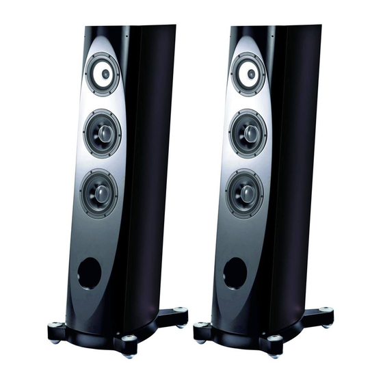
SPEAKER SYSTEM
S-1EX
NOTE
As this speaker system weighs approx. 66 kg, be sure to have two people work on it. If this
speaker system will be turned on its side for servicing, lay it on a piece of soft cloth, etc., to
protect the cabinet from being scratched.
This service manual is intended for qualified service technicians; it is not meant for the casual do-it-
yourselfer. Qualified technicians have the necessary test equipment and tools, and have been trained to
properly and safely repair complex products such as those covered by this manual.
Improperly performed repairs can adversely affect the safety and reliability of the product and may void the
warranty. If you are not qualified to perform the repair of this product properly and safely, you should not risk
trying to do so and refer the repair to a qualified service technician.
WARNING
This product contains lead in solder and certain electrical parts contain chemicals which are known to the state of California to
cause cancer, birth defects or other reproductive harm.
CONTENTS
1. PARTS LIST .................................................................................. 2
3. SCHEMATIC DIAGRAM ............................................................. 11
4. JIG ............................................................................................... 12
PIONEER CORPORATION
PIONEER ELECTRONICS (USA) INC. P.O. Box 1760, Long Beach, CA 90801-1760, U.S.A.
PIONEER EUROPE NV Haven 1087, Keetberglaan 1, 9120 Melsele, Belgium
PIONEER ELECTRONICS ASIACENTRE PTE. LTD. 253 Alexandra Road, #04-01, Singapore 159936
PIONEER CORPORATION 2006
4-1, Meguro 1-chome, Meguro-ku, Tokyo 153-8654, Japan
XTW/E
Health & Safety Code Section 25249.6 - Proposition 65
ORDER NO.
RRV3337
T - ZZS FEB. 2006 Printed in Japan
Advertisement

Related Manuals for Pioneer S-1EX


Summary of Contents for Pioneer S-1EX
- Page 1 PIONEER CORPORATION 4-1, Meguro 1-chome, Meguro-ku, Tokyo 153-8654, Japan PIONEER ELECTRONICS (USA) INC. P.O. Box 1760, Long Beach, CA 90801-1760, U.S.A. PIONEER EUROPE NV Haven 1087, Keetberglaan 1, 9120 Melsele, Belgium PIONEER ELECTRONICS ASIACENTRE PTE. LTD. 253 Alexandra Road, #04-01, Singapore 159936 PIONEER CORPORATION 2006 T –...
-
Page 2: Parts List
NOTES : ÷ Parts marked by “ NSP ” are generally unavailable because they are not in our Master Spare Parts List. ÷ The > mark found on some component parts indicates the importance of the safety factor of the part. Therefore, when replacing, be sure to use parts of identical designation. 1.1 PACKING Speaker system S-1EX... - Page 3 Finishing Screws (for grille) SLH6014 Polyethylene Bag S0 SHL1259 Accessory Set SME6037 Screw (for metal catch) BMZ40P120FTB Metal Catch FRNH-028 Polyethylene Bag S0 SHL1259 Accessory Sset (for grille holes) SME6047 Caps (for grille holes) SEC2068 Polyethylene Bag S0 SHL1259 Label Serial SRW1112 S-1EX...
- Page 4 72 (x8) (Long cords) (Short cords) Upper side for the HPF input terminals 60 (x4) Lower side for the 65 (x4) LPF input terminals 44 (x4) (x8) (x4) (x16) (x6) : Refer to the adhesive points on page 9 (x4) S-1EX...
- Page 5 Speaker (MID/TW) A14GR55-52DX Screw (bottom spike - base) BKC50P300FTB 4.9 max. Screw (spike top - base) BMZ40P400FTB Hexagon Socket Screw SBA1225 (for WF, MID/TW) Screw (for NW assy) SBA1260 Screw (for closure panel) SBA1261 Screw (base - cabinet) SBA1262 S-1EX...
- Page 6 (bottom side) Specification for attaching the packing for the Bottom spike The direction of the cord holes must be vertical. The direction of the cord holes must be vertical. Front View Back View No.32 Grille S-1EX...
- Page 7 Gasket (for screw holes) SEC2050 Gasket (base top) SEC2051 Gasket (base top) SEC2052 Gasket (base top) SEC2053 Gasket (for spike (top)) SEC2055 Input Terminal (Red) SKX6027 Input Terminal (Black) SKX6028 NSP 75 Model Label SAN3790 Country Label SAN3782 Label Serial SRW1111 S-1EX...
-
Page 8: For Precaution Of Reassembly And Disassembly
: White with Black line Upper side Coaxial unit Terminal size: : White with Black line White tape Extra large White tape Lower woofer Terminal board Short cord Terminal size: of the midrange Terminal size: Large Large : White : White S-1EX... - Page 9 Fig. 2-4: Specifications for attaching the : Screws : Screws closure panel (cross-sectional view of the Fig. 2-2: Specifications for attaching Fig. 2-3: Specifications for attaching the coaxial-unit speaker) the Network Assy for the woofers Network Assy for the midrange/tweeter S-1EX...
- Page 10 2 rolls of acoustic absorbent pads. Place one roll lengthwise, push it into the front of the top board of the cabinet, then push another beneath of the first one. Fig. 2-8: After the lower woofer is removed (4) S-1EX...
-
Page 11: Schematic Diagram
White White with Black line with Black line 22µF/250V INPUT 0.8mH 0.3mH TWEETER COIL COIL 3Ω/10w White White 2.7µF/250V 12µF/250V White 68µF/100V with Black line 47µF/250V 1.2mH 2.2Ω/10w COIL 14µF/250V MIDRANGE 15µF/250V 15µF/250V White 0.47Ω/10w 0.82mH 0.82mH COIL COIL S-1EX... -
Page 12: Jig
For removal/reattachment of the speaker unit GGK1024 Box wrench (14 mm) For removal/reattachment of the Network Assy GGH-002 7 Adhesives list to be used Adhesive Name Part No. Remarks DIABOND (Black) (DB-1600WB) GYL-014 For removal/reattachment of the Network Assy S-1EX...