Table of Contents
Advertisement
Quick Links
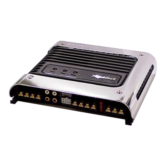
SERVICE MANUAL
Ver. 1.0 2006. 11
Sony Corporation
9-887-489-01
2006K04-1
eVehicle Division
© 2006. 11
Published by Sony Techno Create Corporation
SPECIFICATIONS
AUDIO POWER SPECIFICATIONS (US model)
POWER OUTPUT AND TOTAL HARMONIC DISTORTION
50 watts per channel minimum continuous average power into 4 ohms,
both channels driven from 20 Hz to 20 kHz with no more than 0.04% total
harmonic distortion per Car Audio Ad Hoc Committee standards.
Other Specifications
Circuit system
OTL (output transformerless) circuit
Pulse power supply
Inputs
RCA pin jacks
High level input connector
Input level adjustment range
0.3 – 6 V (RCA pin jacks),
1.2 – 12 V (High level input)
Outputs
Speaker terminals
Speaker impedance
2 – 8 Ω (stereo)
4 – 8 Ω (when used as a bridging amplifier)
Maximum output
4 speakers: 95 W × 4 (at 4 Ω)
3 speakers: 95 W × 2 + 250 W × 1 (at 4 Ω)
Rated output (supply voltage at 14.4 V)
4 speakers:
50 W × 4 (20 Hz – 20 kHz, 0.04% THD, at 4 Ω)
60 W × 4 (20 Hz – 20 kHz, 0.1% THD, at 2 Ω)
Frequency response
5 Hz – 100 kHz (
Harmonic distortion
0.005% or less (at 1 kHz, 4 Ω, 10 W)
Low-pass filter
80 Hz, –18 dB/oct
High-pass filter
80 Hz, –12 dB/oct
Low Boost
0 – 10 dB (40 Hz)
Power requirements
12 V DC car battery (negative ground)
Power supply voltage
10.5 – 16 V
Current drain
at rated output : 27 A (4 Ω, 50 W × 4)
Remote input : 1 mA
Dimensions
Approx. 223 × 43.5 × 196 mm
× 1
× 7
(8
7/8
3/4
not incl. projecting parts and controls
Mass
Approx. 2.2 kg (4 lb 14 oz) not incl. accessories
Supplied accessories
Mounting screws (4)
High level input cord (1)
Design and specifications are subject to change without
notice.
XM-4S
+0
dB)
–3
in.) (w/h/d)
3/4
STEREO POWER AMPLIFIER
US Model
Canadian Model
AEP Model
UK Model
E Model
1
Advertisement
Table of Contents

Related Manuals for Sony XM-4S


Summary of Contents for Sony XM-4S
-
Page 1: Service Manual
Approx. 2.2 kg (4 lb 14 oz) not incl. accessories Supplied accessories Mounting screws (4) High level input cord (1) Design and specifications are subject to change without notice. STEREO POWER AMPLIFIER Sony Corporation 9-887-489-01 2006K04-1 eVehicle Division © 2006. 11 Published by Sony Techno Create Corporation... - Page 2 • Never reuse a disconnected chip component. NE REMPLACER CES COMPOSANTS QUE PAR DES PIÈCES • Notice that the minus side of a tantalum capacitor may be SONY DONT LES NUMÉROS SONT DONNÉS DANS CE MANUEL OU DANS LES SUPPLÉMENTS PUBLIÉS PAR SONY. damaged by heat.
-
Page 3: Table Of Contents
XM-4S TABLE OF CONTENTS 1. GENERAL Location and Function of Controls .......... 4 Connections ................5 2. DISASSEMBLY 2-1. MAIN Board Section ............8 2-2. FILTER Board ..............9 2-3. MAIN Board ............... 9 3. DIAGRAMS 3-1. Block Diagram ..............11 3-2. -
Page 4: General
XM-4S SECTION 1 GENERAL This section is extracted from instruction manual. Location and Function of Controls Features 1 LEVEL adjustment control 5 LOW BOOST level control • Maximum power output of 95 W per channel (at 4 * Pulse power supply... -
Page 5: Connections
XM-4S Connections Installation Block Diagram Before Installation First, place the unit where you plan to install it, and mark the positions of the four screw holes on the surface Schéma fonctionnel • Mount the unit either inside the trunk or under a seat. - Page 6 • Do not connect any active speakers (with built-in In such a case, consult your nearest Sony dealer. amplifiers) to the speaker terminals of the unit. Doing so may damage the active speakers.
- Page 7 XM-4S Input Connections/Connexions d’entrée/Conexiones de entrada Speaker Connections/Connexions des haut-parleurs/ Conexiones de los altavoces Turn on or off the LPF and HPF switch at the unit rear as illustrated below. High Level Input Connection Activez ou désactivez le commutateur LPF et HPF situé à l’arrière de l’appareil, comme illustré ci-dessous.
-
Page 8: Disassembly
XM-4S SECTION 2 DISASSEMBLY Note : This set can be disassemble according to the following sequence. 2-1. MAIN BOARD SECTION (Page 8) 2-2. FILTER BOARD 2-3. MAIN BOARD (Page 9) (Page 9) Note : Follow the disassembly procedure in the numerical order given. -
Page 9: Filter Board
XM-4S 2-2. FILTER BOARD 2 two screws (+PTT 2.6 × 4) 4 screw (+PTT 2.6 × 4) 5 two screws (+PTT 2.6 × 4) 3 FILTER board 1 CN811 (2P) 7 LED-XPLOD board main heat sink 2-3. MAIN BOARD 1 three screws (+P 3 ×... -
Page 10: Diagrams
XM-4S SECTION 3 DIAGRAMS • Waveform THIS NOTE IS COMMON FOR PRINTED WIRING BOARDS AND SCHEMATIC DIAGRAMS. IC903 5 (In addition to this, the necessary note is printed in each block.) for schematic diagram: 3.1 Vp-p Note: • All capacitors are in µF unless otherwise noted. (p: pF) 50 WV or less are not indicated except for electrolytics and tantalums. -
Page 11: Block Diagram
XM-4S 3-1. BLOCK DIAGRAM (FRONT) PRE AMP CN903 IC801 (2/2) OVERLOAD GAIN CONTROL AMP MUTE FRONT IC805 (2/2) CN902 (1/2) SWITCH SPEAKER Q112 Q101 DIFFERENTIAL DRIVE DRIVE POWER IC803 (2/2) VR801-1 Q103 Q104 Q108 Q110 SW801-1 BIAS MUTE CONTROL Q106,107... -
Page 12: Circuit Boards Location
XM-4S 3-2. CIRCUIT BOARDS LOCATION • Semiconductor Location • Semiconductor Location (Main Section (1/2)) (Main Section (2/2)) Ref. No. Location Ref. No. Location D101 D803 D102 D804 D201 D805 LED-FOOT-L board D202 D806 D301 D807 B-11 D302 D808 D401 D809... -
Page 13: Printed Wiring Boards -Main Section (1/2)
XM-4S 3-3. PRINTED WIRING BOARDS — MAIN SECTION (1/2) — • Refer to page 12 for Circuit Boards Location and Semiconductor Location. : Uses unleaded solder. D401 Q402 Q403 D402 R456 R373 R353 R354 Q301 C252 R371 R471 JR201 C253... -
Page 14: Printed Wiring Boards -Main Section (2/2)
XM-4S 3-4. PRINTED WIRING BOARDS — MAIN SECTION (2/2) — • Refer to page 12 for Circuit Boards Location and Semiconductor Location. : Uses unleaded solder. TP56 TP55 C917 TP47 TP46 Q410 Q411 Q310 Q311 Q406 Q306 R270 TP45 TP26... -
Page 15: Schematic Diagram -Main Section (1/2)
XM-4S 3-5. SCHEMATIC DIAGRAM — MAIN SECTION (1/2) — D101 R159 R158 R175 R155 Q108 Q103 C118 Q104 R170 C152 Q110 R174 JR101 Q112 R167 R177 C119 Q101 C151 C153 R165 R163 R153 Q106 CN903 R161 C154 TP43 R169 R173... -
Page 16: Schematic Diagram -Main Section (2/2)
XM-4S 3-6. SCHEMATIC DIAGRAM — MAIN SECTION (2/2) — • Refer to page 10 for Waveform and page 19 for IC Block Diagram. (Page 15) R805 C805 TP50 TP26 Q807 Q812 Q811 Q809 Q810 R926 T901 C819 TP24 D803 C826... -
Page 17: Printed Wiring Boards -Filter Section
XM-4S 3-7. PRINTED WIRING BOARDS — FILTER SECTION — • Refer to page 12 for Circuit Boards Location. : Uses unleaded solder. • Semiconductor Location Ref. No. Location IC803 IC804 IC805 IC806 IC807 Q300 (LED802) G-2 IC805 Q400 (LED803) H-2... -
Page 18: Schematic Diagram -Filter Section
XM-4S 3-8. SCHEMATIC DIAGRAM — FILTER SECTION — VR801 R113 C111 R108 R112 SW801 C109 LED804 LED803 C112 CN810 CN809 C108 IC803(2/2) C110 C806 R822 CN802(1/2) CN803(1/2) R109 IC805(2/2) R111 R110 R114 LED802 R209 R211 R210 R214 (Page 15) IC805(1/2) -
Page 19: Ic Block Diagram
XM-4S • IC Block Diagram IC903 TL594INSR (MAIN BOARD (2/2)) REF 5V ERROR ERROR 0.1V... -
Page 20: Exploded Views
XM-4S SECTION 4 EXPLODED VIEWS NOTE: • The mechanical parts with no reference • Color Indication of Appearance Parts The components identified by mark 0 or dotted line with mark number in the exploded views are not supplied. Example : 0 are critical for safety. -
Page 21: Main Board Section
XM-4S 4-2. MAIN BOARD SECTION not supplied (LED-FOOT-L board) not supplied not supplied Q311,Q310 (LED-FOOT-R board) Q111,Q110, Q211,Q210 not supplied Q411,Q410 not supplied F901 Q913,Q912,Q911, Q910,D804,D803 Ref. No. Part No. Description Remark Ref. No. Part No. Description Remark A-1216-760-A MAIN BOARD, COMPLETE... -
Page 22: Electrical Parts List
XM-4S SECTION 3 FILTER ELECTRICAL PARTS LIST NOTE: • Due to standardization, replacements in • SEMICONDUCTORS The components identified by mark 0 or dotted line with mark the parts list may be different from the In each case, u : µ, for example: 0 are critical for safety. - Page 23 XM-4S FILTER LED-FOOT-L LED-FOOT-R LED-XPLOD MAIN Ref. No. Part No. Description Remark Ref. No. Part No. Description Remark R419 1-216-837-11 METAL CHIP 1/10W A-1216-760-A MAIN BOARD, COMPLETE R420 1-216-819-11 METAL CHIP 1/10W ********************* R421 1-216-829-11 METAL CHIP 4.7K 1/10W 3-225-184-12 SCREW (+PS.TT.3XL) <...
- Page 24 XM-4S MAIN Ref. No. Part No. Description Remark Ref. No. Part No. Description Remark C801 1-115-340-11 CERAMIC CHIP 0.22uF < JACK > C802 1-126-934-11 ELECT 220uF C803 1-115-340-11 CERAMIC CHIP 0.22uF CN902 1-779-078-41 JACK, PIN 4P (INPUT (FRONT/REAR)) C804 1-115-340-11 CERAMIC CHIP 0.22uF...
- Page 25 XM-4S MAIN Ref. No. Part No. Description Remark Ref. No. Part No. Description Remark < COIL > Q410 8-729-024-80 TRANSISTOR 2SC5100-Y Q411 8-729-024-76 TRANSISTOR 2SA1908-P L801 1-410-396-71 INDUCTOR, FERRITE BEAD 0.45uH Q411 8-729-024-77 TRANSISTOR 2SA1908-Y L901 1-481-205-11 COIL, CHOKE 50uH...
- Page 26 XM-4S MAIN Ref. No. Part No. Description Remark Ref. No. Part No. Description Remark R166 1-216-814-11 METAL CHIP 1/10W R305 1-216-849-11 METAL CHIP 220K 1/10W R167 1-216-793-11 METAL CHIP 1/10W R306 1-216-835-11 METAL CHIP 1/10W R168 1-216-793-11 METAL CHIP 1/10W...
- Page 27 XM-4S MAIN Ref. No. Part No. Description Remark Ref. No. Part No. Description Remark R468 1-216-793-11 METAL CHIP 1/10W R927 1-216-801-11 METAL CHIP 1/10W R469 1-205-991-11 ENCAPSULATED COMPONENT 0.1X2 5W R928 1-216-789-11 METAL CHIP 1/10W R470 1-216-833-11 METAL CHIP 1/10W...
- Page 28 XM-4S Ref. No. Part No. Description Remark ACCESSORIES ************ 2-891-668-11 MANUAL, INSTRUCTION (ENGLISH,FRENCH, SPANISH) (US,CND,AEP,UK) 2-891-668-21 MANUAL, INSTRUCTION (GERMAN,SWEDISH) (AEP,UK) 2-891-668-31 MANUAL, INSTRUCTION (DUTCH,PORTUGUESE) (AEP,UK) 2-891-668-41 MANUAL, INSTRUCTION (ITALIAN,POLISH) (AEP,UK) 2-891-668-51 MANUAL, INSTRUCTION (GREEK,RUSSIAN) (AEP,UK) 2-891-795-11 MANUAL, INSTRUCTION (ENGLISH,FRENCH) (E,IND)
- Page 29 XM-4S MEMO...
- Page 30 XM-4S REVISION HISTORY Clicking the version allows you to jump to the revised page. Also, clicking the version at the upper on the revised page allows you to jump to the next revised page. Ver. Date Description of Revision 2006. 11...