Yamaha DVX-S301 Service Manual
Dvd home theater sound system
Hide thumbs
Also See for DVX-S301:
- Owner's manual (456 pages) ,
- Service manual (68 pages) ,
- Owner's manual (65 pages)
Table of Contents
Advertisement
Quick Links
DVD HOME THEATER SOUND SYSTEM
DVR-S300/
I CONTENTS
TO SERVICE PERSONNEL ...................................... 2~3
PREVENTION OF ELECTROSTATIC DISCHARGE ........ 4
LOCALE MANAGEMENT INFORMATION ................... 4
SYSTEM COMPOSITION / システム構成 ..................... 5
FRONT PANELS ........................................................ 6~7
REMOTE CONTROL ...................................................... 8
REAR PANELS ........................................................ 8~12
SPECIFICATIONS / 参考仕様 ................................ 13~15
INTERNAL VIEW ......................................................... 16
REPAIR NOTES / 修理上の留意点 .............................. 17
DVR-S300 トレードモード ........................................ 18
分解手順 ............................................................... 19~21
分解手順 ............................................................... 22~23
1 0 0 9 6 5
Downloaded From DvDPlayer-Manual.com Yamaha Manuals
本资料由OKXIA视听皮带资源库www.okxia.cn提供
This manual has been provided for the use of authorized YAMAHA Retailers and their service personnel.
It has been assumed that basic service procedures inherent to the industry, and more specifically YAMAHA Products, are already
known and understood by the users, and have therefore not been restated.
WARNING:
Failure to follow appropriate service and safety procedures when servicing this product may result in personal
injury, destruction of expensive components, and failure of the product to perform as specified. For these reasons,
we advise all YAMAHA product owners that any service required should be performed by an authorized
YAMAHA Retailer or the appointed service representative.
IMPORTANT:
The presentation or sale of this manual to any individual or firm does not constitute authorization, certification or
recognition of any applicable technical capabilities, or establish a principle-agent relationship of any form.
The data provided is believed to be accurate and applicable to the unit(s) indicated on the cover. The research, engineering, and
service departments of YAMAHA are continually striving to improve YAMAHA products. Modifications are, therefore, inevitable
and specifications are subject to change without notice or obligation to retrofit. Should any discrepancy appear to exist, please
contact the distributor's Service Division.
WARNING:
Static discharges can destroy expensive components. Discharge any static electricity your body may have
accumulated by grounding yourself to the ground buss in the unit (heavy gauge black wires connect to this buss).
IMPORTANT:
Turn the unit OFF during disassembly and part replacement. Recheck all work before you apply power to the unit.
2005
This manual is copyrighted by YAMAHA and may not be copied or
redistributed either in print or electronically without permission.
DVX-S301/DVX-S302
NX-P301/NX-P302
SERVICE MANUAL
SERVICE MANUAL
SERVICE MANUAL
IMPORTANT NOTICE
DVR-S300 BLOCK DIAGRAM .................................... 25
NX-SW301 BLOCK DIAGRAM .............................. 26~27
DVR-S300 WIRING DIAGRAM .................................... 28
NX-SW301 WIRING DIAGRAM ................................... 29
DVR-S300 PRINTED CIRCUIT BOARD ............... 30~37
NX-SW301 PRINTED CIRCUIT BOARD ............... 38~41
DVR-S300 SCHEMATIC DIAGRAM ...................... 42~55
NX-SW301 SCHEMATIC DIAGRAM ..................... 56~60
NX-SW301 PARTS LIST ........................................ 61~63
DVR-S300 EXPLODED VIEW ............................... 64~65
NX-P301 EXPLODED VIEW .................................. 66~67
NX-P302 EXPLODED VIEW ........................................ 68
All rights reserved.
P.O.Box 1, Hamamatsu, Japan
'05.08
Advertisement
Table of Contents

Related Manuals for Yamaha DVX-S301


Summary of Contents for Yamaha DVX-S301
-
Page 1: Table Of Contents
This manual has been provided for the use of authorized YAMAHA Retailers and their service personnel. It has been assumed that basic service procedures inherent to the industry, and more specifically YAMAHA Products, are already known and understood by the users, and have therefore not been restated. -
Page 2: To Service Personnel
Do not あります。 adjust this laser level control unless instruction is provided elsewhere in this manual. Adjustment of this control can increase the laser emission level from the device. Downloaded From DvDPlayer-Manual.com Yamaha Manuals... - Page 3 The screws on the DVD mechanism may never be touched, removed or re-adjusted. Handle the DVD mechanism with care when the unit has to be exchanged! The DVD mechanism is very sensitive for dropping or giving shocks. Downloaded From DvDPlayer-Manual.com Yamaha Manuals...
-
Page 4: Prevention Of Electrostatic Discharge
M a c r o v i s i o n C o r p o r a t i o n . R e v e r s e engineering or disassembly is prohibited. Downloaded From DvDPlayer-Manual.com Yamaha Manuals... -
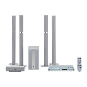
Page 5: System Composition / システム構成
I SYSTEM COMPOSITION / システム構成 The DVX-S301 consists of the DVR-S300 and the NX-P301. The DVX-S302 consists of the DVR-S300 and the NX-P302. DVX-S301 (C, K, A, B, G, L, V, J models) DVX-S302 (C, K, A, B, G, L, V models) DVR-S300... -
Page 6: Front Panels
DVR-S300/ NX-P301/NX-P302 I FRONT PANELS DVR-S300 (C, K, A, B, G, L, V models) (J model) NX-SW301 Downloaded From DvDPlayer-Manual.com Yamaha Manuals... - Page 7 DVR-S300/ NX-P301/NX-P302 NX-S301 NX-C301 NX-C302 NX-S302 Downloaded From DvDPlayer-Manual.com Yamaha Manuals...
-
Page 8: Remote Control
DVR-S300/ NX-P301/NX-P302 I REMOTE CONTROL C, K, A, B, G, L, V models J model I REAR PANELS DVR-S300 (C model) DVR-S300 (K model) Downloaded From DvDPlayer-Manual.com Yamaha Manuals... - Page 9 DVR-S300/ NX-P301/NX-P302 DVR-S300 (A model) DVR-S300 (B, G models) DVR-S300 (L model) DVR-S300 (V model) DVR-S300 (J model) Downloaded From DvDPlayer-Manual.com Yamaha Manuals...
- Page 10 DVR-S300/ NX-P301/NX-P302 NX-SW301 (C model) NX-SW301 (K model) NX-SW301 (A model) NX-SW301 (B, G models) Downloaded From DvDPlayer-Manual.com Yamaha Manuals...
- Page 11 DVR-S300/ NX-P301/NX-P302 NX-SW301 (L model) NX-SW301 (V model) NX-SW301 (J model) Downloaded From DvDPlayer-Manual.com Yamaha Manuals...
- Page 12 DVR-S300/ NX-P301/NX-P302 NX-S301 NX-C301 NX-C302 NX-S302 Downloaded From DvDPlayer-Manual.com Yamaha Manuals...
-
Page 13: Specifications / 参考仕様
328 x 98 x 64 mm (14-3/16" x 2-1/16" x 12-3/16") (12-15/16" x 3-7/8" x 2-1/2") Weight 2.7 kg (5 lbs. 15 oz.) Weight 0.7 kg (1 lbs. 8 oz.) Finish Silver Color Finish Silver Color Downloaded From DvDPlayer-Manual.com Yamaha Manuals... - Page 14 Advanced YST Active Servo Processing Subwoofer System with built-in power amplifier. This subwoofer system (NX-SW301) employes Advanced YAMAHA Active Servo Technology which YAMAHA has developed for reproducing higher quality super-bass sound. This super-bass sound adds a more realistic, theater-in-the-home effect to your stereo syetem.
- Page 15 151 ( 5-15/16" ) ( 3-1/4" ) ( 3-1/16" ) NX-C301 110 ( 4-3/8" ) 328 ( 12-15/16" ) ( 2-9/16" ) Unit : mm (inch) 300 ( 11-13/16" ) 単位 : mm (インチ) ( 3-1/16" ) Downloaded From DvDPlayer-Manual.com Yamaha Manuals...
-
Page 16: Internal View
8 FRONT (2) HP P.C.B. 9 FRONT (1) DISPLY P.C.B. NX-SW301 POWER (3) IN/OUT P.C.B. AMP (1) FL/FR P.C.B. AMP (2) SL/SR P.C.B. POWER (1) C/SW P.C.B. POWER (4) SUBTR P.C.B. POWER (2) POWER P.C.B. Downloaded From DvDPlayer-Manual.com Yamaha Manuals... -
Page 17: Repair Notes / 修理上の留意点
When turning on the power of NX-SW301 indepen- 動作確認のためにNX-SW301単独で電源をONする場 dently for its operation check, refer to “When check- 合、 「 NX-SW301分解手順」 の 「P.C.B.動作チェックを ■ ing the P.C.B.” of “I NX-SW301 DISASSEMBLY する場合」 ( 23ページ) を参照してください。 PROCEDURES” (on page 23). Downloaded From DvDPlayer-Manual.com Yamaha Manuals... -
Page 18: Dvr-S300 Trade Mode / Dvr-S300 トレードモード
す。 (Fig. 2) control in that order. (Fig. 2) 3. 本体FLディスプレイに “TRA OFF” が表示され、トレー 3. “TRA OFF” appears on the FL display of the main unit ドモードが解除されます。 (Fig. 4) and TRADE MODE is cancelled. (Fig. 4) Downloaded From DvDPlayer-Manual.com Yamaha Manuals... -
Page 19: Dvr-S300 Disassembly Procedures / 分解手順
Turn the player bottom up. a. 本体を上下反転します。 b. Move the slider in the direction indicated with a b. トレーが出てくるまで、マイナスドライバーでスラ flatblade screwdriver until the tray is ejected. イダーを図に示す矢印の方向に動かします。 c. Gently pull the tray out. c. トレーをそっと引き出します。 Downloaded From DvDPlayer-Manual.com Yamaha Manuals... - Page 20 Remove 4 screws (A). (Fig. 5) b. A のネジ4本を外します。 (Fig. 5) c. Remove MONO P.C.B.. c. MONO P.C.B.を取り外します。 1302 MONO P.C.B. 1301 1101 1102 MONO P.C.B. DVD MECHANISM DVDメカ 1105 1104 1103 DVD MECHANISM DVDメカ Fig. 4 Fig. 5 Downloaded From DvDPlayer-Manual.com Yamaha Manuals...
- Page 21 HDMI D2 P.C.B. (J model) 1102 CON1 1601 1704 (J model) AV P.C.B. 1401 1201 1101 Snap スナップ Fig. 6 (J model) D (C, K, A, B, G, L, V models) D (B, G models) Fig. 7 Downloaded From DvDPlayer-Manual.com Yamaha Manuals...
-
Page 22: Nx-Sw301 Disassembly Procedures / 分解手順
確認し、エアー漏れが発生しないように組み立てて air leakage from occurring. ください。 Front Grille Ass'y フロントグリルASSY Rear Panel Ass'y リアパネル ASSY Flatblade Screwdriver マイナスドライバー Dowel ダボ Bottom Side 底面 Heat Sink Cover ヒートシンクカバー Fig. 1 Fig. 2 Downloaded From DvDPlayer-Manual.com Yamaha Manuals... - Page 23 CONNECTOR. b. 電源コードをAC電源コンセントに接続します。 b. Connect the power cable to the AC power outlet. POWER (3) IN/OUT P.C.B. SYSTEM CONNECTOR Short 11 12 13 14 15 9 10 POWER (3) IN/OUT SCHEMATIC DIAGRAM Short SYSTEM CONNECTOR Downloaded From DvDPlayer-Manual.com Yamaha Manuals...
- Page 24 DVR-S300/ NX-P301/NX-P302 MEMO Downloaded From DvDPlayer-Manual.com Yamaha Manuals...
-
Page 25: Dvr-S300 Block Diagram
B, G models 7204 TUNER (TM 08) (SAA6581) B, G models AM/FM TUNER 7200 7507 MONO Board C, K, A, B, G, L, V models HDMI D2 Board J model DVD MECHANISM B, G models Downloaded From DvDPlayer-Manual.com Yamaha Manuals... -
Page 26: Nx-Sw301 Block Diagram
PROTE PROTE RLY-SP RLY-SP RLY Tr Q208 DC Detect Q207,206 CN204 Over TEMP Tr Thermister EH3P IC202 TH201 IC201 Current Q204 Q209,210 PLY-SP KIA4558P STK403-090 Detect -12V RY201 +12V Q202 CN203 VH3P AMP (2) SL/SR Downloaded From DvDPlayer-Manual.com Yamaha Manuals... -
Page 27: Nx-Sw301 Block Diagram
Q807 D804 (Blue) (White) KTC3198 1SR139-400 SCN3P SCN3P KLA78L05 T802 IC803 C813 R822 470/25V 4.7K CN808 CN810 TE801 TE802 D805 1SR139-400 Q809,810 C814 POWER (4) R823 4.7/50V SUB TRANSFORMER IC804 Q808 AC IN KTA1266 R824 Downloaded From DvDPlayer-Manual.com Yamaha Manuals... -
Page 28: Dvr-S300 Wiring Diagram
GND_D SCL-DAC SD6.31 SDA-DAC 8002 1105 RDS_CLK RDS_DAT AV BOARD 8009 1108 AM/FM TUNER VSDA_DAC VSDA VSCL_DAC VSCK DAC_STB RDS_DAT 8004 (J model) 8011 1109 HDMI D2 BOARD (J model) PLUG DET PLUG DET 8005 Downloaded From DvDPlayer-Manual.com Yamaha Manuals... -
Page 29: Nx-Sw301 Wiring Diagram
SPEAKER TERMINAL SYSTEM CONNECTOR POWER (3) IN/OUT BOARD POWER (1) C/SW BOARD AMP (1) FL/FR BOARD AMP (2) SL/SR BOARD CN305 DRIVER WOOFER POWER (4) SUBTR BOARD CN810 CN808 POWER CABLE POWER (2) POWER BOARD Downloaded From DvDPlayer-Manual.com Yamaha Manuals... -
Page 30: Dvr-S300 Printed Circuit Board
6xxx : Diode 9xxx : Wire jumper FOR INFORMATION ONLY (NO REPLACEMENT COMPONENT PARTS WILL BE AVAILABLE) MONO Board-Top View FRONT (1) DISPLAY BOARD 1301 AV BOARD 1101 Page 34 Page 32 AV BOARD 1201 Page 32 Downloaded From DvDPlayer-Manual.com Yamaha Manuals... - Page 31 7xxx : IC, Transistor, FET I DVR-S300 PRINTED CIRCUIT BOARD 2xxx : Capacitor 4xxx : SMD jumper 6xxx : Diode 9xxx : Wire jumper FOR INFORMATION ONLY (NO REPLACEMENT COMPONENT PARTS WILL BE AVAILABLE) MONO Board-Bottom View Downloaded From DvDPlayer-Manual.com Yamaha Manuals...
- Page 32 C, K, A, B, G, L, V models AV MONITOR OUT (DVD ONLY) VIDEO / COMPONENT OPTICAL LINE OUT TV IN AUX IN SYSTEM S VIDEO Y / P CONNECTOR VIDEO OUT (DVD ONLY) DIGITAL IN ANALOG IN/OUT Downloaded From DvDPlayer-Manual.com Yamaha Manuals...
- Page 33 4xxx : SMD jumper 6xxx : Diode 9xxx : Wire jumper AV Board-Bottom View FOR INFORMATION ONLY (NO REPLACEMENT COMPONENT PARTS WILL BE AVAILABLE) C, K, A, B, G, L, V models B, G models Downloaded From DvDPlayer-Manual.com Yamaha Manuals...
- Page 34 9xxx : Wire jumper FOR INFORMATION ONLY (NO REPLACEMENT COMPONENT PARTS WILL BE AVAILABLE) FRONT (1) Display Board-Top View POWER SUPPLY UNIT CONTROL BOARD 1100 MONO BOARD 1105 Page 36 Page 30 FRONT (1) Display Board-Bottom View Downloaded From DvDPlayer-Manual.com Yamaha Manuals...
- Page 35 4xxx : SMD jumper 6xxx : Diode 9xxx : Wire jumper FOR INFORMATION ONLY (NO REPLACEMENT COMPONENT PARTS WILL BE AVAILABLE) FRONT (2) HP Board-Top View FRONT (2) HP Board-Bottom View CONTROL BOARD 1103 Page 36 HEADPHONE Downloaded From DvDPlayer-Manual.com Yamaha Manuals...
- Page 36 FOR INFORMATION ONLY (NO REPLACEMENT COMPONENT PARTS WILL BE AVAILABLE) CONTROL Board-Top View FRONT (2) HP BOARD 1400 Page 35 AV BOARD 1601 FRONT (1) DISPLAY BOARD 1302 Page 32 Page 34 CONTROL Board-Bottom View Downloaded From DvDPlayer-Manual.com Yamaha Manuals...
-
Page 37: Dvr-S300 Printed Circuit Board
4xxx : SMD jumper 6xxx : Diode 9xxx : Wire jumper FOR INFORMATION ONLY (NO REPLACEMENT COMPONENT PARTS WILL BE AVAILABLE) HDMI D2 Board-Top View (J model) HDMI D2 Board-Bottom View (J model) D1/D2 モニター出力 Downloaded From DvDPlayer-Manual.com Yamaha Manuals... -
Page 38: Nx-Sw301 Printed Circuit Board
AMP (1) FL/FR Board-Top View AMP (2) SL/SR Board-Top View POWER (2) POWER BOARD CN801 POWER (3) IN/OUT BOARD CN403 Page 40 Page 40 POWER (3) IN/OUT BOARD CN402 POWER (2) POWER BOARD CN802 Page 40 Page 40 Downloaded From DvDPlayer-Manual.com Yamaha Manuals... - Page 39 POWER (2) POWER BOARD CN801 POWER (3) IN/OUT BOARD CN403 Page 40 Page 41 R161 R162 R163 R164 R261 R262 R263 R264 POWER (3) IN/OUT BOARD CN402 POWER (2) POWER BOARD CN802 Page 41 Page 40 Downloaded From DvDPlayer-Manual.com Yamaha Manuals...
- Page 40 POWER (3) IN/OUT BOARD CN405 Page 40 POWER (3) IN/OUT Board-Top View POWER (4) SUBTR Board-Top View SUBTRANS SPEAKER TERMINAL SYSTEM CONNECTOR POWER (2) POWER BOARD CN804 POWER (2) POWER BOARD CN808 Page 40 Page 40 Downloaded From DvDPlayer-Manual.com Yamaha Manuals...
-
Page 41: Nx-Sw301 Printed Circuit Board
POWER (2) POWER BOARD CN803 DRIVER Page 40 POWER (3) IN/OUT Board-Top View (Specifications for the beginnings of production / 生産初期の仕様) SPEAKER TERMINAL SYSTEM CONNECTOR R138/C121 R314/C308 R137/C122 POWER (2) POWER BOARD CN804 Page 40 Downloaded From DvDPlayer-Manual.com Yamaha Manuals... -
Page 42: Dvr-S300 Schematic Diagram
B4B-PH-K 2245 I5 7106 D5 # Components having special characteristics are marked s and must be replaced with parts having specifications equal to those originally installed. # Schematic diagram is subject to change without notice. Downloaded From DvDPlayer-Manual.com Yamaha Manuals... - Page 43 SPDIF_ERR_CTRL 4311 A1 4312 A2 # Components having special characteristics are marked s and must be replaced with parts having specifications equal to those originally installed. # Schematic diagram is subject to change without notice. Downloaded From DvDPlayer-Manual.com Yamaha Manuals...
- Page 44 T133 1102 DGND DGND 4110 # Components having special characteristics are marked s and must be replaced with parts having specifications equal to those originally installed. # Schematic diagram is subject to change without notice. Downloaded From DvDPlayer-Manual.com Yamaha Manuals...
- Page 45 DGND 5208 C2 5209 C4 # Components having special characteristics are marked s and must be replaced with parts having specifications equal to those originally installed. # Schematic diagram is subject to change without notice. Downloaded From DvDPlayer-Manual.com Yamaha Manuals...
- Page 46 GND_A 3363 C7 3364 C8 # Components having special characteristics are marked s and must be replaced with parts having specifications equal to those originally installed. # Schematic diagram is subject to change without notice. Downloaded From DvDPlayer-Manual.com Yamaha Manuals...
- Page 47 100n 2423 100n GND_A DGND # Components having special characteristics are marked s and must be replaced with parts having specifications equal to those originally installed. # Schematic diagram is subject to change without notice. Downloaded From DvDPlayer-Manual.com Yamaha Manuals...
- Page 48 4513 E11 4514 E11 4515 E11 # Components having special characteristics are marked s and must be replaced with parts having specifications equal to those originally installed. # Schematic diagram is subject to change without notice. Downloaded From DvDPlayer-Manual.com Yamaha Manuals...
- Page 49 T604 C8 6603 Mutec BAS316 # Components having special characteristics are marked s and must be replaced with parts having specifications equal to those originally installed. # Schematic diagram is subject to change without notice. Downloaded From DvDPlayer-Manual.com Yamaha Manuals...
- Page 50 NO(4722) NO(4724) NO(4718) NO(4713) NO(4714) # Components having special characteristics are marked s and must be replaced with parts having specifications equal to those originally installed. # Schematic diagram is subject to change without notice. Downloaded From DvDPlayer-Manual.com Yamaha Manuals...
- Page 51 7803 A4 7804 B4 7805 D7 # Components having special characteristics are marked s and must be replaced with parts having specifications equal to those originally installed. # Schematic diagram is subject to change without notice. Downloaded From DvDPlayer-Manual.com Yamaha Manuals...
-
Page 52: Display Panel
GND_FD GND_FD 3374 B12 GND_D GND_FD 3307 3375 B12 3376 B12 3377 B12 3378 C12 * 3342 - 150 YAMAHA S300 GND_FD GND_FD GND_FD 3379 C12 - NIL PHILIPS HTS5500 3380 C12 4301 H4 4302 H4 4303 E3 5300 B7... - Page 53 GND_HP 2403 1410 470n RT-01T-1.0B # Components having special characteristics are marked s and must be replaced with parts having specifications equal to those originally installed. # Schematic diagram is subject to change without notice. Downloaded From DvDPlayer-Manual.com Yamaha Manuals...
- Page 54 GND_HP GND_HP GND_HP GND_B GND_B # Components having special characteristics are marked s and must be replaced with parts having specifications equal to those originally installed. # Schematic diagram is subject to change without notice. Downloaded From DvDPlayer-Manual.com Yamaha Manuals...
-
Page 55: Dvr-S300 Schematic Diagram
3127 LINE_3 PLUGDETN * Option # Components having special characteristics are marked s and must be replaced with parts having specifications equal to those originally installed. # Schematic diagram is subject to change without notice. Downloaded From DvDPlayer-Manual.com Yamaha Manuals... -
Page 56: Nx-Sw301 Schematic Diagram
I NX-SW301 SCHEMATIC DIAGRAM AMP (1) FL/FR BOARD # Components having special characteristics are marked s and must be replaced with parts having specifications equal to those originally installed. # Schematic diagram is subject to change without notice. Downloaded From DvDPlayer-Manual.com Yamaha Manuals... - Page 57 I NX-SW301 SCHEMATIC DIAGRAM AMP (2) SL/SR BOARD # Components having special characteristics are marked s and must be replaced with parts having specifications equal to those originally installed. # Schematic diagram is subject to change without notice. Downloaded From DvDPlayer-Manual.com Yamaha Manuals...
- Page 58 I NX-SW301 SCHEMATIC DIAGRAM POWER (1) C/SW BOARD # Components having special characteristics are marked s and must be replaced with parts having specifications equal to those originally installed. # Schematic diagram is subject to change without notice. Downloaded From DvDPlayer-Manual.com Yamaha Manuals...
- Page 59 Page 58 POWER (4) SUBTR BOARD # Components having special characteristics are marked s and must be replaced with parts having specifications equal to those originally installed. # Schematic diagram is subject to change without notice. Downloaded From DvDPlayer-Manual.com Yamaha Manuals...
-
Page 60: Nx-Sw301 Schematic Diagram
TO CN302 OF POWER (1) C/SW BOARD Page 58 # Components having special characteristics are marked s and must be replaced with parts having specifications equal to those originally installed. # Schematic diagram is subject to change without notice. Downloaded From DvDPlayer-Manual.com Yamaha Manuals... -
Page 61: Nx-Sw301 Parts List
: IC PROTECTOR VR.MTR : POTENTIOMETER WITH MOTOR JUMPER.CN : JUMPER CONNECTOR VR.SW : POTENTIOMETER WITH ROTARY SW JUMPER.TST : JUMPER,TEST POINT VR.SLIDE : SLIDE POTENTIOMETER L.DTCT : LIGHT DETECTING MODULE VR.TRIM : TRIMMER POTENTIOMETER Downloaded From DvDPlayer-Manual.com Yamaha Manuals... - Page 62 044153 不燃化カーボン抵抗 s RY101 VU161600 RELAY OSA-SS-224DM3 079766 リレー s RY201 VU161600 RELAY OSA-SS-224DM3 079766 リレー ✻ New Parts * 新規部品 Note) Those parts marked with “#” are not included in the P.C.B. ass’y. (マーク#の部品は、 基板に含まれません) Downloaded From DvDPlayer-Manual.com Yamaha Manuals...
- Page 63 ✻ New Parts * 新規部品 ✻ New Parts * 新規部品 Note) Those parts marked with “#” are not included in the P.C.B. ass’y. (マーク#の部品は、 基板に含まれません) Note) Those parts marked with “#” are not included in the P.C.B. ass’y. (マーク#の部品は、 基板に含まれません) Downloaded From DvDPlayer-Manual.com Yamaha Manuals...
-
Page 64: Dvr-S300 Exploded View
2.7 mm 8009 1108 8002 1105 1109 8005 8011 1106-5 J model B, G models J model 8004 1106-1 1107 1103 1104 8007 8001 Note) The replacement battery cover is not available. 8008 電池蓋のみの交換はできません。 1103 (1) Downloaded From DvDPlayer-Manual.com Yamaha Manuals... - Page 65 3139 241 01431 カード電線 C&C 8008 AAX71740 FLEXIBLE FLAT CABLE 9P 100mm P=1mm 3139 241 01461 カード電線 C&C 8009 AAX67170 FLEXIBLE FLAT CABLE 11P 100mm P=1mm 3103 308 93911 カード電線 C&C ✻ New Parts * 新規部品 ✻ New Parts * 新規部品 Downloaded From DvDPlayer-Manual.com Yamaha Manuals...
-
Page 66: Nx-P301 Exploded View
DVR-S300/ NX-P301/NX-P302 I NX-P301 EXPLODED VIEW (3) IN/OUT (1) C/SW (2) SL/SR (1) FL/FR (4) SUBTR 5m x 3 for NX-SW301 for NX-C301 (2) POWER 15m x 2 Downloaded From DvDPlayer-Manual.com Yamaha Manuals... - Page 67 ✻ New Parts * 新規部品 ✻ New Parts * 新規部品 Note) Those parts marked with “#” are not included in the P.C.B. ass’y. (マーク#の部品は、 基板に含まれません) Note) Those parts marked with “#” are not included in the P.C.B. ass’y. (マーク#の部品は、 基板に含まれません) Downloaded From DvDPlayer-Manual.com Yamaha Manuals...
-
Page 68: Nx-P302 Exploded View
NX-S302 1pc NX-SP302F000050 ベース 202-2 AAX71540 LEG ASS'Y M15 t=11 1pair NX-SP302000040 レッグASSY 03753460 BIND HEAD SCREW 5x10 MFNI33 1pc バインド小ネジ VZ890800 WASHER 5.5x8x0.3 1pc ワッシャー AAX73160 FASTENER 25x25 2pairs 57045&57046 固定テープ ✻ New Parts * 新規部品 Downloaded From DvDPlayer-Manual.com Yamaha Manuals...