Yamaha DVX-S200 Service Manual
Home theater sound system
Hide thumbs
Also See for DVX-S200:
- Owner's manual (115 pages) ,
- Product catalog (44 pages) ,
- Supplementary manual (40 pages)
Table of Contents
Advertisement
Quick Links
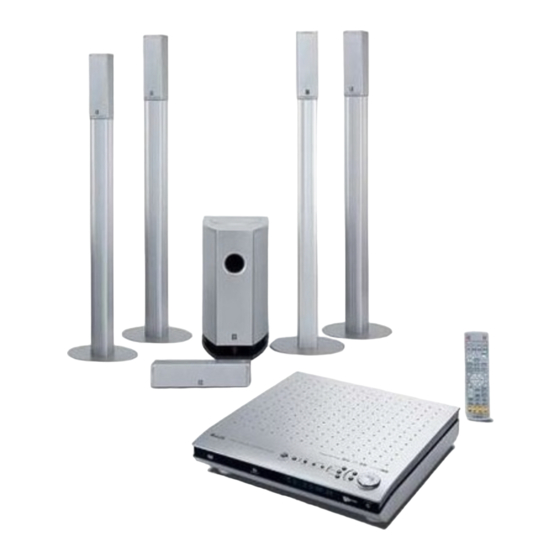
HOME THEATER SOUND SYSTEM
DVR-S200/
The DVX-S200 is composed of the DVR-S200 and the NX-P200.
DVX-S200 は DVR-S200 と NX-P200 で構成されています。
This manual has been provided for the use of authorized YAMAHA Retailers and their service personnel.
It has been assumed that basic service procedures inherent to the industry, and more specifically YAMAHA Products, are already
known and understood by the users, and have therefore not been restated.
WARNING:
IMPORTANT:
The data provided is believed to be accurate and applicable to the unit(s) indicated on the cover. The research, engineering, and service
departments of YAMAHA are continually striving to improve YAMAHA products. Modifications are, therefore, inevitable and
specifications are subject to change without notice or obligation to retrofit. Should any discrepancy appear to exist, please contact the
distributor's Service Division.
WARNING:
IMPORTANT:
CONTENTS
TO SERVICE PERSONNEL . . . . . . . . . . . . . . . . . . 2-4
PREVENTION OF ELECTRO STATIC DISCHARGE . . . . . . 4
LOCALE MANAGEMENT INFORMATION . . . . . . . . 5
システム構成 . . . . . . . . . . .
FRONT PANELS . . . . . . . . . . . . . . . . . . . . . . . . . . . 6-7
REMOTE CONTROL PANELS . . . . . . . . . . . . . . . . . . 7
REAR PANELS . . . . . . . . . . . . . . . . . . . . . . . . . . . . 8-9
SPECIFICATIONS /
参考仕様 . . . . . . . . . . . . . . . .
INTERNAL VIEW . . . . . . . . . . . . . . . . . . . . . . . . . . . . 14
DVR-S200分解手順 . . . . . . . . . . . . . . . . . . . . . . . .
NX-SW200分解手順 . . . . . . . . . . . . . . . . . . . . . . .
1 0 0 8 7 1
IMPORTANT NOTICE
Failure to follow appropriate service and safety procedures when servicing this product may result in personal
injury, destruction of expensive components, and failure of the product to perform as specified. For these reasons,
we advise all YAMAHA product owners that any service required should be performed by an authorized YAMAHA
Retailer or the appointed service representative.
The presentation or sale of this manual to any individual or firm does not constitute authorization, certification or
recognition of any applicable technical capabilities, or establish a principle-agent relationship of any form.
Static discharges can destroy expensive components. Discharge any static electricity your body may have
accumulated by grounding yourself to the ground buss in the unit (heavy gauge black wires connect to this buss).
Turn the unit OFF during disassembly and part replacement. Recheck all work before you apply power to the unit.
5
10-13
15-19
20-21
. . . . . . . . 22
Copyright 2004 YAMAHA CORPORATION
This manual is copyrighted by YAMAHA and may not be copied or
redistributed either in print or electronically without permission.
DVX-S200
NX-P200
SERVICE MANUAL
SERVICE MANUAL
DVR-S200自己診断機能(ダイアグ)
DVR-S200 DVDダイアグモード
DISPLAY DATA . . . . . . . . . . . . . . . . . . . . . . . . . . . . . 47
IC DATA . . . . . . . . . . . . . . . . . . . . . . . . . . . . . . . . 48-57
DVR-S200 BLOCK DIAGRAM . . . . . . . . . . . . . . 58-60
DVR-S200 PRINTED CIRCUIT BOARD . . . . . . . 61-70
NX-SW200 PRINTED CIRCUIT BOARD . . . . . . . . . 71
DVR-S200 SCHEMATIC DIAGRAM . . . . . . . . . . 72-87
NX-SW200 SCHEMATIC DIAGRAM . . . . . . . . . . . . 88
PARTS LIST . . . . . . . . . . . . . . . . . . . . . . . . . . . . 89-107
REMOTE CONTROL . . . . . . . . . . . . . . . . . . . . . . . . 108
22
DVR-S200調整 . . . . . .
. . . . . . . . . . 23-45
. . . . . . . . . . . . . . . . 46
Advertisement
Table of Contents

Related Manuals for Yamaha DVX-S200


Summary of Contents for Yamaha DVX-S200
-
Page 1: Table Of Contents
This manual has been provided for the use of authorized YAMAHA Retailers and their service personnel. It has been assumed that basic service procedures inherent to the industry, and more specifically YAMAHA Products, are already known and understood by the users, and have therefore not been restated. -
Page 2: To Service Personnel
DVR-S200/NX-P200 TO SERVICE PERSONNEL AC LEAKAGE 1. Critical Components Information EQUIPMENT WALL TESTER OR Components having special characteristics are marked Z OUTLET UNDER TEST EQUIVALENT and must be replaced with parts having specifications equal to those originally installed. 2. Leakage Current Measurement (For 120V Models Only) When service has been completed, it is imperative to verify INSULATING that all exposed conductive surfaces are properly insulated... - Page 3 DVR-S200/NX-P200 警告:レーザーの安全対策 WARNING: Laser Safety 本機はレーザー光線を放射する部品を搭載しています。こ This product contains a laser beam component. This の部品が放射するレーザー光線は目に損傷を起こします。 component may emit invisible, as well as visible radiation, このレーザー光線から目及び肌を保護するために、本機の which may cause eye damage. To protect your eyes 修理作業中は下記の注意を厳守してください。 and skin from laser radiation, the following precautions must be used during servicing of the unit.
-
Page 4: Prevention Of Electro Static Discharge
DVR-S200/NX-P200 WARNING The use of optical instruments with this product will increase eye hazard. Repair handling should take place as much as possible with a disc loaded inside the player. U, C, R, K, A, G, B, L models U, C, R, K, A, G, B, L models The label is put on the bottom side of the unit. -
Page 5: Locale Management Information
M a c r o v i s i o n C o r p o r a t i o n . R e v e r s e engineering or disassembly is prohibited. SYSTEM COMPOSITION / システム構成 The DVX-S200 is composed of the DVR-S200 and the NX-P200. DVR-S200 NX-P200... -
Page 6: Front Panels
DVR-S200/NX-P200 FRONT PANELS DVR-S200 U, C, R, K, A, L models B, G models J model... -
Page 7: Remote Control Panels
DVR-S200/NX-P200 NX-SW200 NX-C200 NX-S200 REMOTE CONTROL PANELS J model U, C, R, K, A, L models B, G models... -
Page 8: Rear Panels
DVR-S200/NX-P200 REAR PANELS DVR-S200 (U, C, R, K, A, L models) DVR-S200 (B, G models) DVR-S200 (J model) NX-S200 NX-C200 NX-S200 NX-S200 IMPEDANCE 6 OHMS NOMINAL INPUT IMPEDANCE 6 OHMS 30 WATTS NOMINAL INPUT MAXIMUM INPUT 100 WATTS 30 WATTS MAXIMUM INPUT 100 WATTS... - Page 9 DVR-S200/NX-P200 NX-SW200 (U, C models) NX-SW200 (R, L models) NX-SW200 (B, G models) R model: 110-220 VOLTS L model: 220-240 VOLTS NX-SW200 (K model) NX-SW200 (A model) NX-SW200 (J model)
-
Page 10: 参考仕様
DVR-S200/NX-P200 SPECIFICATIONS / 参考仕様 Signal to Noise Ratio (IHF-A Network) / S/N比 DVR-S200 SP OUT (FRONT L/R)(Input shorted, 200mV) ..95 dB INPUT OUTPUT SECTION / 入出力 VIDEO SECTION (VCR, VIDEO1, (VIDEO2)) / ビデオ部 Input / 入力端子 ビデオ信号方式 . . . . . . . . . . Video Signal Type / NTSC/PAL AUDIO (Analog) - Page 11 U ..USA model C ..Canadian model AAC ロゴマーク はドルビーラボラトリーズの登録商標です。 R ..General model K ..Korean model A ..Australian model B ..British model "SILENT CINEMA"is a trademark of YAMAHA CORPORATION. G ..European model 「サイレントシアター/ SILENT THEATER 」はヤマハ株式会社の L ..Singapore model J ..Japanese model 登録商標です。...
- Page 12 DVR-S200/NX-P200 NX-P200 NX-S200 NX-C200 Type / 型式 ....2-way Acoustic Suspension Type / 型式 ....2-way Acoustic Suspension Magnetic Shielding Type Magnetic Shielding Type Driver / スピーカーユニット...
- Page 13 DVR-S200/NX-P200 NX-SW200 NX-SW200 Type / 型式 ..Advanced Yamaha Active Servo Technology Output Power / 出力 . . . . . . . . 100 W (100 Hz, 5 Ω, 10 % THD) Dynamic Power / ダイナミックパワー . . . . . . . . . . 140 W, 5 Ω...
-
Page 14: Internal View
DVR-S200/NX-P200 INTERNAL VIEW DVR-S200 AM/FM TUNER MAIN (2) P.C.B. U, C, R, K, A, L, J models: MAIN (3) P.C.B. B, G models: MAIN (4) P.C.B. MAIN (1) P.C.B. D-AMP MODULE DIGITAL P.C.B. DVD MECHANISM SUB (3) P.C.B. SUB (1) P.C.B. FL P.C.B. -
Page 15: Dvr-S200 Disassembly Procedures / Dvr-S200分解手順
DVR-S200/NX-P200 DVR-S200 DISASSEMBLY PROCEDURES / DVR-S200分解手順 (Remove parts in disassembly order as numbered.) (番号順に部品を取り外してださい。) 1. Removal of Side Cover L/R 1. サイドカバーL/Rの外し方 a. Remove 1 screw ( q ) in Fig. 1. a. qのネジ1 本を外します。 ( Fig. 1) b. Lift the Side Cover L at the rear and move it rear-ward b. - Page 16 DVR-S200/NX-P200 HOW TO MANUALLY EJECT THE TRAY Tray / トレー Slider / スライダー a. Remove the Side Cover L/R. b. Remove the Bottom Cover. c. Move the slider in the direction indicated. d. Gently pull the tray out. 手動でトレーを開く方法 a. サイドカバーL/Rを外します。 b. ボトムカバーを外します。 c. スライダーを矢印の方向に動かします。 d.
- Page 17 DVR-S200/NX-P200 4. Removal of DVD Mechanism 4. DVDメカニズムの外し方 a. Remove 2 screws ( i ) and then remove the Top a. iのネジ2本を外し、 トップフレームを外します。 Frame in Fig. 5. (Fig. 5) b. Remove 4 screws ( o ) and then remove the DVD b.
- Page 18 DVR-S200/NX-P200 5. Removal of DIGITAL P.C.B. 5. DIGITAL P.C.B.の外し方 a. Disconnect the connectors CB305, CB103, CB106, a. コネクターCB305、 CB103、 CB106、 CB366、 CB941を外し CB366 and CB941 in Fig. 6. ます。 ( Fig. 6) b. Remove 4 screws ( !0 ) and then remove the DIGITAL b.
- Page 19 DVR-S200/NX-P200 8. Removal of SUB (3) & SUB (1) P.C.B. 8. SUB (3) & SUB (1) P.C.B.の外し方 a. Remove 2 screws ( !4 ) in Fig. 7. a. !4 の ネジ2本を外します。 ( Fig. 7) b. Remove 2 screws ( !5 ) and 2 screws ( !6 ) and then b.
-
Page 20: Nx-Sw200 Disassembly Procedures / Nx-Sw200分解手順
DVR-S200/NX-P200 NX-SW200 DISASSEMBLY PROCEDURES / NX-SW200分解手順 (Remove parts in disassembly order as numbered.) (番号順に部品を取り外してださい。) 1. スピーカーユニットの外し方 1. Removal of Driver a. q のネジ 3 本を外し、ベースを取り外します。 (Fig.1 ) a. Remove 3 screws ( q ) and then remove the Base. b. w のネジ 4 本を外し、 スピーカーユニットを取り外しま (Fig. - Page 21 DVR-S200/NX-P200 When checking the P.C.B.: P.C.B.動作チェックをする場合 Turn on the power to NX-SW200 according to the following 下記の方法により NX-SW200 に電源を投入します。 procedure. a. Short between the terminals of RY2 (relay). a. RY2 ( リレー) の端子間をショートします。 b. Connect the power cable to the AC power outlet. b.
-
Page 22: Dvr-S200 D-Amp Module Troubleshooting / Dvr-S200 D-アンプモジュールの故障診断
DVR-S200/NX-P200 DVR-S200 D-AMP MODULE TROUBLESHOOTING / DVR-S200 D-アンプモジュールの故障診断 When there is a possibility of the D-Amp Module being de- D-アンプモジュールの故障が疑われる場合、 下記の方法によ fective, use the following procedure to determine whether or り各D-アンプモジュールの故障の有無を判定します。 not it is defective. Step 1 Step 1 電源OFF状態でD-アンプモジュール1個を取り外した後、 本 With the power turned off, remove one D-Amp Module and 機の電源をONします。... -
Page 23: Dvr-S200 Self Diagnosis Function (Diag)
DVR-S200/NX-P200 DVR-S200 SELF DIAGNOSIS FUNCTION (DIAG) / DVR-S200自己診断機能 (ダイアグ) This product has a built-in self diagnosis function (DIAG) to 本機には、 検査、 測定、 不良個所の発見を目的にした自己診 facilitate inspection, measurement and determination of a 断機能 (ダイアグ) があります。 faulty item, if any. There are 14 DIAG menu items, each having ダイアグメニューは14個あり、... - Page 24 DVR-S200/NX-P200 No. DIAG menu Sub-menu 9. BSI (YSS) 1 10. BSI (YSS) 2 11. BSI (YSS) 3 12. BSI (YSS) 4 13. BSI (CS) 1 14. BSI (CS) 2 15. BSI (CS) 3 16. BSI (CS) 4 17. BSI (CS) 5 18.
- Page 25 DVR-S200/NX-P200 ダイアグの起動 Starting DIAG ● 本体の A/B/C/D/E キーを押しながら STANDBY/ON While pressing the “A/B/C/D/E” key on the main unit, press キーを押し、表示点灯後4秒以内に PRESET/BAND the “STANDBY/ON” key until the FL display lights up. Within キーを押すとダイアグが起動します。 4 seconds after that, press the “PRESET/BAND” key to start the DIAG function.
- Page 26 DVR-S200/NX-P200 Display provided when DIAG started ダイアグ起動時の表示 ● On the FL display of the main unit, an opening message 本体FLディスプレイには、オープニング (プロテクショ ン履歴/バージョン) が表示され、数秒後にダイアグメ (including the version and the protection history) appears ニュー表示 (ANALOG BYPAS) となります。 for a few seconds followed by the diagnostic menu dis- play of ANALOG BYPAS.
- Page 27 DVR-S200/NX-P200 The protection function worked due to a de- 電源 (DVD関連以外) による原因で、プロテ fect or overload in the power supply (but not クションが働いたことを示します。異常状 PRT:000 C related to the DVD). If the power is turned on 態のままパワーオンすると、約1秒後にプロ with the abnormality unsolved, the protection テクションが掛かり、電源が切れます。...
- Page 28 DVR-S200/NX-P200 ダイアグメニューとサブメニューの操作 ● Operation procedure of DIAG menu and ダイアグにはNo.1〜14のメニューがあり、さらにいくつ SUB-MENU かのサブメニューがあります。 There are 14 MENU items and some SUB-MENU items as well. ダイアグメニューの選択 本体 :PRESET TUNING N (順送り) /B (逆送り) キー DIAG menu selection サブメニューの選択 Main unit: PRESET TUNING N(forward)/B(reverse) key 本体...
- Page 29 DVR-S200/NX-P200 Details of DIAG menu ダイアグメニュー詳細 With full-bit output specified in some modes, it is possible to 一部のモードでフルビット指定することで、各チャンネ execute 0dBFS output without head margin in each channel. ルのヘッドマージンを廃して 0dBFS 出力することが可能 です。 1. DSP THROUGH 1. DSP THROUGH Main DSP of YSS938 is selected for MAIN L/R output. MAIN L/R 出力には YSS938 の Main DSP が選択されます。 ANALOG BYPASS ANALOG BYPASS • The signal for L/R is output as it is without passing ・L/R は、DSP 部を通らずにそのまま出力されます。...
- Page 30 DVR-S200/NX-P200 YSS FULL BIT YSS FULL BIT • The signal is output in digital full bit without including the ・ヘッドマージンを含まず、デジタルフルビットで出力さ head margin. The SWFR signal is output but not in digital れます。SWFR は出力されますが、デジタルフルビット full bit. ではありません。 YSS FULL BIT Input level Volume SPEAKERS OUT (1KHz) SUBWOOFER FRONT L/R CENTER...
- Page 31 DVR-S200/NX-P200 2. RAM THROUGH 2. RAM THROUGH This function is for YSS938 only. YSS938 のみの動作です。 Only the CT signal is output through the Sub DSP – DRAM. CT のみが Sub DSP − DRAM 経由で出力されます。 RAM 0dB RAM 0dB RAM 0dB Input level Volume SPEAKERS OUT (1KHz) SUBWOOFER FRONT L/R CENTER SURROUND L/R (50 Hz)
- Page 32 DVR-S200/NX-P200 3. PRO LOGIC 3. PRO LOGIC The L/C/R/RL/RR signals undergo the Pro-Logic process- L/C/R/RL/RR は YSS938 によりプロロジック処理され、C/ ing and C/RL/RR signals are output through Sub DSP-DRAM. RL/RR は Sub DSP‐DRAM 経由で出力されます。MAIN L/ Main DSP is selected for MAIN L/R output. R 出力には Main DSP が選択されます。 Using the sub-menu, it is possible to select PRO LOGIC I, II サブメニューで...
- Page 33 DVR-S200/NX-P200 4. SPEAKERS SET 4. SPEAKERS SET The input signal is automatically identified and switched in 入力は信号検出によって、 dts →DOLBY DIGITAL → AAC → the priority order of dts →DOLBY DIGITAL → AAC → PCM PCM AUDIO →アナログ (A/D) の優先順で自動判別切り換え AUDIO → Analog (A/D) according to the signal detection. されます。 The signals output from the DSP block are the same as 1.
- Page 34 DVR-S200/NX-P200 5. MARGIN CHECK 5. MARGIN CHECK The signal is output including the head margin. ヘッドマージンを含んで出力されます。 MAIN 12dB MARGIN MAIN 12dB MARGIN MAIN 12dB Input level Volume SPEAKERS OUT (1KHz) SUBWOOFER FRONT L/R CENTER SURROUND L/R (50 Hz) - ∞ - ∞ - ∞ 1kHz, Both ch, -20 dBm -10 dB (90) +8.5 dBm...
- Page 35 DVR-S200/NX-P200 6. DISPLAY CHECK 6. DISPLAY CHECK This program is used to check the FL display section. The FL 表示部のチェックプログラムです。 サブメニュー操作に display condition varies as shown below according to the より、 表示状態が以下のように変わります。 sub-menu operation. The signals are processed using EF- 信号処理はEFFECT OFF ( ANALOG MAIN BYPASSでL/Rを FECT OFF (The L/R signal is output using ANALOG MAIN 出力)...
- Page 36 DVR-S200/NX-P200 7. MANUAL TEST 7. MANUAL TEST The noise generator built into the DSP outputs the test noise DSP 内蔵のノイズ発生回路によって、サブメニューで指定 through the channels specified by the sub-menu. したチャンネルへテストノイズを出力します。 The noise frequency for LFE is 35 to 250 Hz. Other than LFE 用のノイズ周波数は35 〜250Hz 、 それ以外は中心周波 that, the center frequency is 800Hz.
- Page 37 DVR-S200/NX-P200 8. FACTORY PRESET 8. FACTORY PRESET This menu is used to reserve and inhibit initialization of the バックアップ用RAM (音場プログラムのパラメーターや back-up RAM. The signals are processed using EFFECT セットメニュー内容等) の初期化を予約/禁止します。 OFF. (The L/R signal is output using ANALOG MAIN BY- 信号処理はEFFECT OFF と同じです (ANALOG MAIN BY- PASS.) PASSで、...
- Page 38 DVR-S200/NX-P200 9. AD DATA CHECK/FAN TEST 9. AD DATA CHECK/FAN TEST This menu is used to display the A/D conversion value of the 本体パネルキー、 プロテクションなどを検出している端子の terminals which detect the panel keys of the main unit and A/D変換の値を、 サブメニューで%表示します。 信号処理は実 protection functions in % using the sub-menu. During signal 行前の状態を維持します。...
- Page 39 DVR-S200/NX-P200 TH/Fa (temperature detection/fan drive level) TH/Fa (温度検出/ファン駆動レベル) 500% display of the voltage based on the tempera- 温度検出値で電圧の500 %表示、 基準電圧は5V ture detected value. Reference voltage : 5V (正常値1 〜257) (Normal value: 1 to 257) 左側は現在のファン駆動レベル、 右側は過去のファン Current fan drive level on the left and the past fan 駆動履歴...
- Page 40 DVR-S200/NX-P200 10. IF STATUS 10. IF STATUS (Input function status) サブメニュー操作により、以下のステータス情報を順次 16 Using the sub-menu, the status data is displayed one after 進数で表示します。信号処理は、本メニュー実行前の状態 another in the hexadecimal notation. を維持します。 During signal processing, the status before execution of this ※図中の数値は参考例です。 menu is maintained. * Numeric values in the figure example are for reference.
- Page 41 DVR-S200/NX-P200 IS2 ‐ 3 (内部ステータス) : (使用しません) IS2-3 (Internal status): (Not used in this model) IS2:480101 IS3:01011001 CS1-5: Indicates channel status information of the input sig- CS 1 ‐ 5: 入力信号のIEC60958 チャンネルステータス情報を nal (IEC60958). (Not used in this model) 表示します。 (使用しません) CS1:FFFFFFFF CS5:FFFFFFFF BY1 ‐...
- Page 42 DVR-S200/NX-P200 11. DSP RAM CHECK 11. DSP RAM CHECK This menu is used to self-diagnose whether or not the bus YSS938と外付けRAMとのバス接続の正否を自己診断します。 connection for the YSS938 and the external RAM is made 信号処理は、 このメニューを実行する前の状態を維持します。 properly. アドレスバス、 データバスのチェックを行い、 接続正否を表 During signal processing, the status before execution of this 示します。...
- Page 43 DVR-S200/NX-P200 12. SOFT SW 12. SOFT SW This menu is used to confirm the function settings on P.C.B.. P.C.B. 上の機能設定を確認する機能です。 SW MODE: Select PCB. Do not select SOFT. PCB を選択してください。SOFT には設定しないでください。 :PCB MODEL SETTING: Select S200. Do not select S120. MODEL:S200 S200 を選択してください。S120 には設定しないでください。 TUNER DESTINATION: J, UC, AGTK or RL can be confirmed.
- Page 44 DVR-S200/NX-P200 13. マイコン情報 13. MICROPROCESSOR INFORMATION The version, checksum and the port specified by the micro- サブメニューは 4 つあります。 processor are displayed. The signal is processed using EF- プログラムのバージョン、チェックサム、マイコンの指定 FECT OFF. The checksum is obtained by adding the data at ポートを表示します。 every 8 bits for each program area and expressing the result 信号はエフェクト...
- Page 45 DVR-S200/NX-P200 14. その他の情報 14. Other Information Soft Date / ソフトの日付 Date03.10.08 Rom Correction Exit, Not / ROM コレクションデータの有無 (Not used in this model) / (使用しません) RomCorr NOT Rom Correction Check Sum Display / ROM コレクションエリアのチェックサム R.C.Sum:---- (Not used in this model) /(使用しません) Rom Correction Remote Control Receive ROM コレクションデータのリモコン受信 EEPROM NONE! (Not used in this model) /(使用しません) Remote Control Code Display / リモコン受信コード表示 Remote control received code can be checked. (See page 108) / リモコン...
-
Page 46: Dvr-S200 Dvd Diag Mode
DVR-S200/NX-P200 DVR-S200 DVD DIAG MODE / DVR-S200 DVDダイアグモード D V D ダイアグモードを使って、 サブC P U のバージョン・ It is possible to have the sub-CPU version, checksum and チェックサム及びバージョンマトリックスを表示すること version matrix displayed by using the DVD DIAG mode. ができます。 Operation procedure 操作方法 ● Perform operation by using the keys on the main unit while 本体FLディスプレイを見ながら、... -
Page 47: Display Data
DVR-S200/NX-P200 DISPLAY DATA V941 : 14-BT-80GNKF (WB452200) PATTERN AREA PIN CONNECTION Pin No. Connection F1 NX NP NP 1G 2G 3G 4G 5G 6G 7G 8G 9G 10G 11G 12G 13G 14G NX NX NX P35 P34 P33 P32 P31 P30 P29 P28 P27 Pin No. -
Page 48: Ic Data
DVR-S200/NX-P200 IC DATA IC308 : M30624FGAFP (DIGITAL P.C.B.) Main CPU Name Port Function SOUT4 Electronic Volume IC DATA (Serial I/O-4) CLK4 Electronic Volume IC CLOCK (Serial I/O-4) D-A OUT FAN D-A OUT (FAN) [0 ~ VCC] DAC (CS4382) CONTROL CS OUT [L: DATA Transfer] SOUT3 S-OUT... - Page 49 DVR-S200/NX-P200 IC308 : M30624FGAFP (DIGITAL P.C.B.) Main CPU Name Port Function RDS IC RxD (RDS_RXD) (Pull-up resistor required) CMOS VMUTE 2 Power supply, +5V CMOS (Pull-down resistor required) Aspect Select WIDE 2 CMOS CMOS Aspect Select WIDE 1 CMOS (Pull-down resistor required) CMOS VIDEO Selector D CMOS...
- Page 50 DVR-S200/NX-P200 IC307 : M38517FP (DIGITAL P.C.B.) SUB CPU Name Port Function Power supply, +5V A-D, D-A Reference Voltage Input [ ~ VCC] VREF Connect to Vss (GND) AVSS (Pull-down resistor required) INT3 (Pull-down resistor required) INT2 Interrupt Request from Main Microprocessor [H: IRQ] INT1 INT-IN...
- Page 51 DVR-S200/NX-P200 IC303 : YSS938 (DIGITAL P.C.B.) RAMA10 RAMD2 RAMA11 RAMD1 RAMD0 VDD2 VDD2 SELI8 SELI7 OPORT7 SELI6 OPORT6 SELI5 OPORT5 RAMA12 OPORT4 RAMA13 OPORT3 RAMA14 OPORT2 RAMA15 OPORT1 RAMA16 OPORT0 RAMA17 ZEROBF2L OVFB/END ZEROBF2R ZEROFLG ZEROBF3L ZEROBF3R NONPCM VDD1 DTSDATA SDOB0 AC3DATA SDOB1...
- Page 52 DVR-S200/NX-P200 IC303 : YSS938 (DIGITAL P.C.B.) Name Function Crystal oscillator connecting terminal Crystal oscillator connecting terminal (24.576MHz ) SELI1 Built-in selector input 1 (Unconnected) SELI0 Built-in selector input 0 (GND) SELOA Built-in selector output A (ISEL) SELOB Built-in selector output B (RSEL) TESTMS Test terminal (unconnected)
- Page 53 DVR-S200/NX-P200 IC303 : YSS938 (DIGITAL P.C.B.) Name Function SDWCKI1 Word clock input terminal for SDIB, SDOB interface (Unconnected) SDBCKI1 Bit clock input terminal for SDIB, SDOB interface (Unconnected) Ground terminal SDOB3 PCM output terminal from Sub DSP SDOB2 PCM output terminal from Sub DSP SDOB1 PCM output terminal from Sub DSP SDOB0...
- Page 54 DVR-S200/NX-P200 IC303 : YSS938 (DIGITAL P.C.B.) Name Function RAMA5 Sub DSP: External memory address terminal 5 RAMA2 Sub DSP: External memory address terminal 2 SELI13 Built-in selector input 13 (Unconnected) SELI12 Built-in selector input 12 (Unconnected) SELI11 Built-in selector input 11 (Unconnected) SELI10 Built-in selector input 10 (Unconnected) SELI9...
- Page 55 DVR-S200/NX-P200 IC302 : XC9572XL-10Q100C (DIGITAL P.C.B.) ......J only 100 99 98 97 96 95 94 93 92 91 90 89 88 87 86 85 84 83 82 81 80 79 78 77 76 ZIN2 75 GND 74 CSIO[7] ZIN3 73 NC PGND 72 CSIO[6]...
- Page 56 DVR-S200/NX-P200 IC302 : XC9572XL-10Q100C (DIGITAL P.C.B.) ......J only 端子名 信号線名称 機 能 ZIN2 MAIN DAC SDATA 用 セレクタ入力端子:AUDATA0 (GND) N.C. N.C. ZIN3 MAIN DAC SDATA 用 セレクタ入力端子:SDOA0 (GND) PGND 電源 (0V) 電源 (+3.3V) FMEMENINV FMEINV SRAM チップセレクト N.C. N.C. FMEMEN Flash Memory チップセレクト (未接続) EXMEM̲ON /EMOE 外部メモリ用 Output Enable 出力 EMWR̲ON /EMWE 外部メモリ用 Write Enable 出力...
- Page 57 DVR-S200/NX-P200 IC302 : XC9572XL-10Q100C (DIGITAL P.C.B.) ......J only 端子名 信号線名称 機 能 D[4] EMD[4] 外部メモリアクセス用 Data バス D[5] EMD[5] 外部メモリアクセス用 Data バス D[6] EMD[6] 外部メモリアクセス用 Data バス 電源 (+3.3V) D[7] EMD[7] 外部メモリアクセス用 Data バス EXMEM̲IN /EXM2 External Memory OUT Enable from CS49329 PGND 電源 (0V) CSCSO /CSCS3 CS49329 用チップセレクト出力(cscsi のスルー)...
- Page 58 DVR-S200/NX-P200 DVR-S200 BLOCK DIAGRAM (1/3) / ブロックダイアグラム DVD Module Host bus Front-end back-end interface ATAPI / host bus ext1 connector 1603 Front-end Back-end ATARSTn signals signals DD[7] DD[8] 7608 IDERST LDRRSTn LDRRSTn ATARSTn DD[6] DD[9] Single Disc HD(0..7) SD_IN(0..7) DD[5] DD[10] Buffer / voltage connector 1701 FERROR ERROR...
-
Page 59: Dvr-S200 Block Diagram
DVR-S200/NX-P200 DVR-S200 BLOCK DIAGRAM (2/3) / ブロックダイアグラム IC361 See page 86 Q363 HP_DET SCHEMATIC DIAGRAM MAIN See page 82 SCHEMATIC DIAGRAM HP_MUTE IC103 Q364 JK351 IC361 UPC4570 MUTE BA15218F IC103 D-AMP MODULE VCR IN UPC4570 DIGITAL IC111 See page 81 SCHEMATIC DIAGRAM VCR OUT UPC4570 DC Signal Detect J model only... - Page 60 DVR-S200/NX-P200 DVR-S200 BLOCK DIAGRAM (3/3) / ブロックダイアグラム CONTROL CONTROL DIGITAL See page 81 SCHEMATIC DIAGRAM See page 86 SCHEMATIC DIAGRAM 6ch Volume INPUT Selector CONTROL VIDEO SW TUNER & RDS Control Signal DSP Control Signal 29 39 U351 REMOTE REMOTE SENSOR POW_RY Voltage Monitor SW_MUTE R41 ~ R44 SW_MUTE...
-
Page 61: Dvr-S200 Printed Circuit Board
DVR-S200/NX-P200 The first digit of a component indicates the component type. DVR-S200 PRINTED CIRCUIT BOARD 1xxx : Connector 3xxx : Resistor 5xxx : Coil 7xxx : IC, Transistor, FET DVR-S200 2xxx : Capacitor 4xxx : SMD jumper 6xxx : Diode 9xxx : Wire jumper FOR INFORMATION ONLY (NO SERVICE PARTS WILL BE AVAILABLE) - Page 62 DVR-S200/NX-P200 The first digit of a component indicates the component type. DVR-S200 PRINTED CIRCUIT BOARD 1xxx : Connector 3xxx : Resistor 5xxx : Coil 7xxx : IC, Transistor, FET DVR-S200 2xxx : Capacitor 4xxx : SMD jumper 6xxx : Diode 9xxx : Wire jumper FOR INFORMATION ONLY (NO SERVICE PARTS WILL BE AVAILABLE)
- Page 63 DVR-S200/NX-P200 The first digit of a component indicates the component type. DVR-S200 PRINTED CIRCUIT BOARD 1xxx : Connector 3xxx : Resistor 5xxx : Coil 7xxx : IC, Transistor, FET DVR-S200 2xxx : Capacitor 4xxx : SMD jumper 6xxx : Diode 9xxx : Wire jumper FOR INFORMATION ONLY (NO SERVICE PARTS WILL BE AVAILABLE)
- Page 64 DVR-S200/NX-P200 DVR-S200 PRINTED CIRCUIT BOARD (Foil side) DVR-S200 DIGITAL P.C.B. DIGITAL P.C.B. (Lead Type Device) (Surface Mount Device) MAIN (1) MAIN (1) CB106 CB103 MONO MAIN (3) or MAIN (4) MONO 1400 CB803 CB872 1500 J only J only Except J Except J CB941 Point w (Pin 1 of IC303)
- Page 65 DVR-S200/NX-P200 DVR-S200 PRINTED CIRCUIT BOARD (Foil side) DVR-S200 FL P.C.B. (Lead Type Device) SUB (1) SUB (3) DIGITAL CB362 CB306 SUB (5) W351 FL P.C.B. (Surface Mount Device) Point t CH 1 : Emitter of Q950 CH 2 : Colector of Q949 CH 1 CH 2 ↑...
- Page 66 DVR-S200/NX-P200 DVR-S200 PRINTED CIRCUIT BOARD (Foil side) DVR-S200 B, G models MAIN (1) P.C.B. (Lead Type Device) U, C, R, K, A, L, J models SPEAKERS FRONT CENTER FRONT SURROUND SURROUND SUB (1) SUB (3) SUB (3) DIGITAL DIGITAL CB361 CB363 CB301 CB308...
- Page 67 DVR-S200/NX-P200 DVR-S200 PRINTED CIRCUIT BOARD (Foil side) DVR-S200 MAIN (2) P.C.B. MAIN (2) P.C.B. (Lead Type Device) (Surface Mount Device) SYSTEM CONNECTOR DIGITAL AUDIO L305 U, C, R, K, A, B, G, L only MAIN (1) CB111 MAIN (1) P.C.B. (Surface Mount Device) Except B, G B, G only...
- Page 68 DVR-S200/NX-P200 DVR-S200 PRINTED CIRCUIT BOARD (Foil side) DVR-S200 U, C, R, K, A, L, J models B, G models MAIN (3) P.C.B. (Lead Type Device) MAIN (4) P.C.B. (Lead Type Device) MONITOR OUT VIDEO J model U, C, R, K, A, L models MONITOR OUT VIDEO Point r (Pin 12 of IC864)
- Page 69 DVR-S200/NX-P200 DVR-S200 PRINTED CIRCUIT BOARD (Foil side) DVR-S200 SUB (1) P.C.B. SUB (1) P.C.B. (Lead Type Device) (Surface Mount Device) POWER CABLE MAIN (1) MAIN (1) CB101 CB118 Except J CB945 SUB (2) P.C.B. (Lead Type Device)
- Page 70 DVR-S200/NX-P200 DVR-S200 PRINTED CIRCUIT BOARD (Foil side) DVR-S200 SUB (3) P.C.B. SUB (3) P.C.B. SUB (5) P.C.B. (Lead Type Device) (Surface Mount Device) (Lead Type Device) CB943 SUB (5) P.C.B. (Surface Mount Device) SUB (4) P.C.B. (Lead Type Device) VOLUME SUB (4) P.C.B.
-
Page 71: Nx-Sw200 Printed Circuit Board
DVR-S200/NX-P200 NX-SW200 PRINTED CIRCUIT BOARD (Foil side) NX-SW200 MAIN ( 1 ) P. C. B. MAIN ( 6 ) P. C. B. MAIN ( 3 ) P. C. B. INPUT SYSTEM MAIN CONNECTOR MAIN RE (SP+) SPEAKER WH (SP-) MAIN ( 2 ) P. C. B. MAIN ( 7 ) P. -
Page 72: Dvr-S200 Schematic Diagram
DVR-S200/NX-P200 The first digit of a component indicates the component type. 1xxx : Connector 3xxx : Resistor 5xxx : Coil 7xxx : IC, Transistor, FET DVR-S200 SCHEMATIC DIAGRAM (MONO 1/9) 2xxx : Capacitor 4xxx : SMD jumper 6xxx : Diode 9xxx : Wire jumper FOR INFORMATION ONLY (NO SERVICE PARTS WILL BE AVAILABLE) - Page 73 DVR-S200/NX-P200 The first digit of a component indicates the component type. 1xxx : Connector 3xxx : Resistor 5xxx : Coil 7xxx : IC, Transistor, FET DVR-S200 SCHEMATIC DIAGRAM (MONO 2/9) 2xxx : Capacitor 4xxx : SMD jumper 6xxx : Diode 9xxx : Wire jumper FOR INFORMATION ONLY (NO SERVICE PARTS WILL BE AVAILABLE)
- Page 74 DVR-S200/NX-P200 The first digit of a component indicates the component type. 1xxx : Connector 3xxx : Resistor 5xxx : Coil 7xxx : IC, Transistor, FET DVR-S200 SCHEMATIC DIAGRAM (MONO 3/9) 2xxx : Capacitor 4xxx : SMD jumper 6xxx : Diode 9xxx : Wire jumper FOR INFORMATION ONLY (NO SERVICE PARTS WILL BE AVAILABLE)
- Page 75 DVR-S200/NX-P200 The first digit of a component indicates the component type. 1xxx : Connector 3xxx : Resistor 5xxx : Coil 7xxx : IC, Transistor, FET DVR-S200 SCHEMATIC DIAGRAM (MONO 4/9) 2xxx : Capacitor 4xxx : SMD jumper 6xxx : Diode 9xxx : Wire jumper FOR INFORMATION ONLY (NO SERVICE PARTS WILL BE AVAILABLE)
- Page 76 DVR-S200/NX-P200 The first digit of a component indicates the component type. 1xxx : Connector 3xxx : Resistor 5xxx : Coil 7xxx : IC, Transistor, FET DVR-S200 SCHEMATIC DIAGRAM (MONO 5/9) 2xxx : Capacitor 4xxx : SMD jumper 6xxx : Diode 9xxx : Wire jumper FOR INFORMATION ONLY (NO SERVICE PARTS WILL BE AVAILABLE)
- Page 77 DVR-S200/NX-P200 The first digit of a component indicates the component type. 1xxx : Connector 3xxx : Resistor 5xxx : Coil 7xxx : IC, Transistor, FET DVR-S200 SCHEMATIC DIAGRAM (MONO 6/9) 2xxx : Capacitor 4xxx : SMD jumper 6xxx : Diode 9xxx : Wire jumper FOR INFORMATION ONLY (NO SERVICE PARTS WILL BE AVAILABLE)
- Page 78 DVR-S200/NX-P200 The first digit of a component indicates the component type. 1xxx : Connector 3xxx : Resistor 5xxx : Coil 7xxx : IC, Transistor, FET DVR-S200 SCHEMATIC DIAGRAM (MONO 7/9) 2xxx : Capacitor 4xxx : SMD jumper 6xxx : Diode 9xxx : Wire jumper FOR INFORMATION ONLY (NO SERVICE PARTS WILL BE AVAILABLE)
- Page 79 DVR-S200/NX-P200 The first digit of a component indicates the component type. 1xxx : Connector 3xxx : Resistor 5xxx : Coil 7xxx : IC, Transistor, FET DVR-S200 SCHEMATIC DIAGRAM (MONO 8/9) 2xxx : Capacitor 4xxx : SMD jumper 6xxx : Diode 9xxx : Wire jumper FOR INFORMATION ONLY (NO SERVICE PARTS WILL BE AVAILABLE)
- Page 80 DVR-S200/NX-P200 The first digit of a component indicates the component type. 1xxx : Connector 3xxx : Resistor 5xxx : Coil 7xxx : IC, Transistor, FET DVR-S200 SCHEMATIC DIAGRAM (MONO 9/9) 2xxx : Capacitor 4xxx : SMD jumper 6xxx : Diode 9xxx : Wire jumper FOR INFORMATION ONLY (NO SERVICE PARTS WILL BE AVAILABLE)
- Page 81 DVR-S200/NX-P200 IC619 : MM74HCT00SJX DVR-S200 SCHEMATIC DIAGRAM (DIGITAL) Quad 2 Input NAND Page 86 C3 Page 84 G5 Page 82 E8 Page 76 B13 Page 83 H4 Page 87 C1 Page 82 B7 to SUB (3) CB366 to MAIN (4) CB872 to MAIN (1) CB106 to MONO 1500 to MAIN (3) CB803...
- Page 82 DVR-S200/NX-P200 IC101 : BD3841FS DVR-S200 SCHEMATIC DIAGRAM (MAIN 1/4) 9ch Function Switch SURL D-AMP MODULE D-AMP MODULE D-AMP MODULE D-AMP MODULE D-AMP MODULE SURR LOGIC F-SW1: INPUT FUNCTION 1 F-SW2: INPUT FUNCTION 2 -12.7 -12.8 -12.6 -12.8 -12.8 Page 86 F4 -41.8 -41.8 -41.7...
- Page 83 DVR-S200/NX-P200 IC801 : NJM2595D DVR-S200 SCHEMATIC DIAGRAM (MAIN 2/4) Video Switch REGULATOR Vin1 Vin2 75ohm Vout1 Vin3 Vin4 75ohm Vout2 Vin5 75ohm Vout3 IC802 : LA7104M 75Ω Video Driver VIN1+ +VCC NFB1 VOUT1 VIDEO MUTE1 SWITCH VIN2+ VOUT2 W801 Page 82 B6 NFB2 DR CTL to MAIN (1) CB119...
- Page 84 DVR-S200/NX-P200 DVR-S200 SCHEMATIC DIAGRAM (MAIN 3/4) IC864 : LC72722PM RDS decoder VDDA CLOCK VDDD RECOVERY REFERENCE (57kHz) (1187.5Hz) VOLTAGE VSSA VSSD VREF 57kHz ANTIALIASING SMOOTHING DATA MPX IN RDS-ID FILTER FILTER DECODER (SCF) SYNC ERROR CORRECTION SYNC/EC (24 BLOCK DATA) (SOFT DECISION) CONTROLLER CLK(4.332MHz)
- Page 85 DVR-S200/NX-P200 DVR-S200 SCHEMATIC DIAGRAM (MAIN 4/4) Reference No U, C, R, K, A, B, G, L W301 MB10807 MB10818 11.9 11.3 1P1.5 1P1.5 L304 BLM21P600SG 11.8 11.8 11.8 W303 EUROPE L302 SBT-0460TF IC301 : TC74HCT00AF (EL) IC302 : NJM2904M Quad 2 Input NAND Dual OP-Amp –IN –...
- Page 86 DVR-S200/NX-P200 DVR-S200 SCHEMATIC DIAGRAM (SUB) Page 82 J4 to MAIN (1) CB117 -11.9 -11.8 11.4 J100 -11.6 -11.8 1.6K 12.4 12.4 -11.6 12.4 -11.9 12.4 -11.6 12.4 WC36210 WB75460 WC36210 WC36210 WC36210 WC36210 WC36210 AC4.0V X : NOT USED 12.1 Page 81 G1 17.2 to DIGITAL CB309...
- Page 87 DVR-S200/NX-P200 Point t DVR-S200 SCHEMATIC DIAGRAM (FL) CH 1 : Emitter of Q950 CH 2 : Colector of Q949 Page 86 A5 Page 81 H1 to SUB (5) W351 to DIGITAL CB306 CH 1 CH 2 ↑ ↑ AC POWER ON AC POWER OFF (Connect the power cord) (Disconnect the power cord)
-
Page 88: Nx-Sw200 Schematic Diagram
DVR-S200/NX-P200 NX-SW200 SCHEMATIC DIAGRAM POWER AMP L.P.F. H.P.F. BUFFER 53.1 53.1 14.7 -14.9 53.1 INPUT -0.7 LIMITTER -14.9 14.8 SYSTEM CONNECTOR 14.7 -15.0 PROTECTION A.N.I.C. EUROPE -1.9 25.4 -0.4 -15.0 14.7 -23.7 14.7 48.6 IC1 : STK404-120 AC78.9 Power Amp 15.2 POWER BIAS... -
Page 89: Parts List
DVR-S200/NX-P200 PARTS LIST ELECTRICAL PARTS WARNING Components having special characteristics are marked Z and must be ● 印のある部分は、安全確保部品を示しています。部品の交換が必要な場合、 replaced with parts having specifications equal to those originally installed. パーツリストに記載されている部品を使用してください。 ABBREVIATIONS IN THIS LIST ARE AS FOLLOWS : C.A.EL.CHP : CHIP ALUMI. ELECTROLYTIC CAP L.DTCT : LIGHT DETECTING MODULE C.CE... - Page 90 DVR-S200/NX-P200 DVR-S200 P.C.B. DIGITAL Ref. PART NO. Description Remarks Markets 部品名 Rank WC002600 P.C.B. DIGITAL PCB デジタル WC002700 P.C.B. DIGITAL UCRKABGL PCB デジタル * CB301 WA903600 CN 36P SE FMN FMNコネクター * CB302 WC198000 CN 30P TE FMN FMNコネクター * CB303 WC195900 CN 9P TE FMN FMNコネクター * CB304 WC195900 CN 9P TE FMN FMNコネクター ...
- Page 91 DVR-S200/NX-P200 DVR-S200 P.C.B. MAIN Ref. PART NO. Description Remarks Markets 部品名 Rank WC001600 P.C.B. MAIN PCB メイン WC001700 P.C.B. MAIN UCRKAL PCB メイン WC001800 P.C.B. MAIN PCB メイン CB101 LB918050 CN.BS.PIN 5P ベース付ポスト CB102 VB389800 CN.BS.PIN 2P ベースピン * CB103 WA545900 CN 30P TE FMN FFC/FPCコネクタ 01 CB104 VQ963000 CN.BS.PIN 9P ウエハー 01 CB105 VQ962900 CN.BS.PIN 8P...
- Page 92 DVR-S200/NX-P200 DVR-S200 P.C.B. MAIN Ref. PART NO. Description Remarks Markets 部品名 Rank C155 UM397100 C.EL 10uF 16V ケミコン C156 UM397100 C.EL 10uF 16V ケミコン C157 UM397470 C.EL 47uF 16V ケミコン C158 UM397470 C.EL 47uF 16V ケミコン C161 UM398100 C.EL 100uF 16V ケミコン C162 UM398100 C.EL 100uF 16V ケミコン...
- Page 93 DVR-S200/NX-P200 DVR-S200 P.C.B. MAIN Ref. PART NO. Description Remarks Markets 部品名 Rank C829 UR837470 C.EL 47uF 16V JUCRKAL ケミコン C830 UR837470 C.EL 47uF 16V JUCRKAL ケミコン C831 UR837470 C.EL 47uF 16V JUCRKAL ケミコン C832 UR837470 C.EL 47uF 16V JUCRKAL ケミコン C834 UR847330 C.EL 33uF 25V JUCRKAL ケミコン 01 C836 UR866220 C.EL...
- Page 94 DVR-S200/NX-P200 DVR-S200 P.C.B. MAIN Ref. PART NO. Description Remarks Markets 部品名 Rank IC103 XF291A00 IC uPC4570G2 IC IC106 XZ545A00 IC YAC520‑EE2 IC 04 IC107 XZ545A00 IC YAC520‑EE2 IC 04 IC108 XZ545A00 IC YAC520‑EE2 IC 04 IC109 X3905A00 IC TS7ST08F AND ロジックIC 01 IC111 XF291A00 IC uPC4570G2 IC...
- Page 95 DVR-S200/NX-P200 DVR-S200 P.C.B. MAIN & SUB Ref. PART NO. Description Remarks Markets 部品名 Rank Q124 VZ725900 TR 2SD1938F S,T トランジスタ Q125 VZ725900 TR 2SD1938F S,T トランジスタ Q301 VV655700 TR.DGT DTC144EKA デジタルトランジスタ 01 Q302 VV655700 TR.DGT DTC144EKA デジタルトランジスタ 01 Q303 VP872700 TR 2SC4488 S,T トランジスタ 01 Q801 VV655400 TR.DGT DTC114EKA デジタルトランジスタ 01 Q802...
- Page 96 DVR-S200/NX-P200 DVR-S200 P.C.B. SUB Ref. PART NO. Description Remarks Markets 部品名 Rank VT807100 CN.BS.PIN 2P ベースポスト LB918040 CN.BS.PIN 4P ベース付ポスト VL844700 CN.BS.PIN 3P ベース付ポスト LB918050 CN.BS.PIN 5P ベース付ポスト CB351 VB858500 CN.BS.PIN 6P ベースピン CB361 V7827100 SOCKET 4P TE TUC SERIES コネクターソケット CB362 VM688900 CN.BS.PIN 10P FFCコネクター...
- Page 97 DVR-S200/NX-P200 DVR-S200 P.C.B. SUB Ref. PART NO. Description Remarks Markets 部品名 Rank C363 UR857100 C.EL 10uF 35V ケミコン 01 C364 UR837100 C.EL 10uF 16V ケミコン C365 UR837100 C.EL 10uF 16V ケミコン C366 UR838100 C.EL 100uF 16V ケミコン C367 UR838100 C.EL 100uF 16V ケミコン C374 UR838470 C.EL 470uF 16V ケミコン...
- Page 98 DVR-S200/NX-P200 DVR-S200 P.C.B. SUB Ref. PART NO. Description Remarks Markets 部品名 Rank VR510800 TR 2SD2396 J,K トランジスタ 01 VV556400 TR 2SC2412K Q,R,S トランジスタ 01 Q361 VV655000 TR.DGT DTA114EKA デジタルトランジスタ 01 Q362 VV655000 TR.DGT DTA114EKA デジタルトランジスタ 01 Q363 VZ725900 TR 2SD1938F S,T トランジスタ Q364 VZ725900 TR 2SD1938F S,T トランジスタ Q365 VV655400 TR.DGT DTC114EKA デジタルトランジスタ 01...
- Page 99 DVR-S200/NX-P200 DVR-S200 P.C.B. FL Ref. PART NO. Description Remarks Markets 部品名 Rank WC002800 P.C.B. PCB FL CB941 V7667200 CN.BS.PIN 20P TE FFCコネクター * CB943 VC166500 CN.BS.PIN 12P コネクタベースポスト 01 CB944 VM688900 CN.BS.PIN 10P FFCコネクター CB945 VB390300 CN.BS.PIN 7P ベースピン C942 UR818100 C.EL 100uF 6.3V ケミコン C943 UM388100 C.EL 100uF 10V...
- Page 100 DVR-S200/NX-P200 CHIP CAPACITORS Ref. PART NO. Description Remarks Markets 部品名 Rank UF028100 C.EL.CHP 100uF 10V チップケミコン 01 UF037100 C.EL.CHP 10uF 16V チップケミコン 01 UF037470 C.EL.CHP 47uF 16V チップケミコン 01 UF066100 C.EL.CHP 1uF 50V チップケミコン 01 UF066220 C.EL.CHP 2.2uF 50V チップケミコン 01 US034470 C.CE.M.CHP 0.047uF 16V チップセラコン US035100 C.CE.M.CHP 0.1uF 16V チップセラコン US044220 C.CE.M.CHP 0.022uF 25V チップセラコン 01 US061100 C.CE.M.CHP 10pF 50V チップセラコン...
- Page 101 DVR-S200/NX-P200 CHIP RESISTORS Ref. PART NO. Description Remarks Markets 部品名 Rank RD350000 R.CHP 0Ω 1/16W チップ抵抗 01 RD353100 R.CHP 1Ω 1/16W チップ抵抗 01 RD353220 R.CHP 2.2Ω 1/16W チップ抵抗 01 RD353470 R.CHP 4.7Ω 1/16W チップ抵抗 01 RD354100 R.CHP 10Ω 1/16W チップ抵抗 01 RD354330 R.CHP 33Ω 1/16W チップ抵抗 01 RD354470 R.CHP 47Ω 1/16W チップ抵抗 01 RD354750 R.CHP 75Ω 1/16W チップ抵抗 01 RD355100 R.CHP...
- Page 102 DVR-S200/NX-P200 NX-SW200 MAIN P.C.B. Ref. PART NO. Description Remarks Markets 部品名 Rank WB910900 P.C.B. MAIN JUCR PCB MAIN WB911000 P.C.B. MAIN KABGL PCB MAIN VB389900 CN.BS.PIN 3P ベースピン VB390100 CN.BS.PIN 5P ベースピン VP206500 HOLDER.FUS EYF‑52BCT ヒューズホルダー VP206500 HOLDER.FUS EYF‑52BCT ヒューズホルダー UA655100 C.MYLAR 0.1uF 50V マイラーコン 01 UA655820 C.MYLAR 0.82uF 50V...
- Page 103 DVR-S200/NX-P200 NX-SW200 P.C.B. MAIN NX-SW200 P.C.B. MAIN Ref. Ref. PART NO. Description Remarks Markets 部品名 Rank PART NO. Description Remarks Markets 部品名 Rank VD631600 DIODE 1SS133,176 ダイオード 01 R123 HV756100 R.CAR.FP 1KΩ 1/4W 不燃化カーボン抵抗 01 VG442500 DIODE.ZENR MTZJ24B 24V ツェナーダイオード 01 R265 HV755390 R.CAR.FP 390Ω 1/4W 不燃化カーボン抵抗 01 VU264100 DIODE 1SR139‑400 ダイオード 01 VU161600 RELAY...
- Page 104 DVR-S200/NX-P200 DVR-S200 EXPLODED VIEW 3-22 3-15 3-25 1-21 1-84 1-12 1-22 1-16 1-26 1-29 3-13 1-90 1-82 1-1 (3): U,C,R,K,A,L,J 1-84 1-52 (4): G,B 1-13 1-13 1-76 3-21 1-1 (2) 3-18 1-89 1-85 1-27 1-25 1-14 1-85 1-84 3-14 1-84 1-31 1-84 1-88...
- Page 105 DVR-S200/NX-P200 DVR-S200 MECHANICAL PARTS Ref. Ref. PART NO. Description Remarks Markets 部品名 Rank PART NO. Description Remarks Markets 部品名 Rank 1‑76 V7741200 LEG レッグ * 1‑1 WC001600 P.C.B. ASS'Y MAIN PCB メイン * 1‑1 WC001700 P.C.B. ASS'Y MAIN UCRKAL PCB メイン 1‑78 V2879500 SPACER PCB‑M スペーサーPCB−M * 1‑1 WC001800 P.C.B. ASS'Y MAIN PCB メイン ...
- Page 106 DVR-S200/NX-P200 NX-P200 EXPLODED VIEW 3-32 3-34 3-36 3-11 3-37 3-22 3-36 3-32 NX-S200 & NX-C200 requires replacement as a unit. Individual replacement parts will not be supplied. 3-31 NX-S200 と NX-C200はユニット交換です。 3-32 3-19 3-32 3-16 3-20 3-18 3-21 3-33 3-35 3-19 (x 4) (x 1) (x 4) (x 4)
- Page 107 DVR-S200/NX-P200 NX-P200 MECHANICAL PARTS Ref. Ref. PART NO. Description Remarks Markets 部品名 Rank PART NO. Description Remarks Markets 部品名 Rank WB930700 CABINET ASS'Y JUCRKABL キャビネットASSY WC515000 CABINET ASS'Y キャビネットASSY ACCESSORIES 付属品 X4939A00 DRIVER, WOOFER 20cm 6Ω JA2170 スピーカーユニット * 201 WB918300 SYSTEM CONTROL CABLE 1P 5m BLACK 1pc システム接続ケーブル * 3‑1 WB910900 P.C.B. ASS'Y MAIN JUCR...
-
Page 108: Remote Control
DVR-S200/NX-P200 REMOTE CONTROL J model U, C, R, A, K, L models B, G models CODE Function TUNER SHIFT (DVD) CD-R POWER 78-0F 78-0F 78-0F 78-0F 78-0F 78-0F TV POWER TV (Preset) Code Transmit 78-11 7C-94 – 78-99 79-85 7F-91 78-12 7C-95 7C-AD...