
Related Manuals for Toro 74270


Summary of Contents for Toro 74270
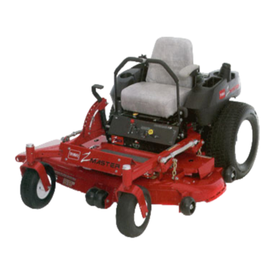
- Page 1 Form No. 3323–196 Compact Series Z147 with 44 SFS Side Discharge Mower Model No. 74270–200000001 & Up Operator’s Manual English (GB)
- Page 2 The warning system in this manual identifies potential hazards and has special safety messages that All of us at Toro want you to be completely satisfied help you and others avoid personal injury, even death. with your new product, so feel free to contact your...
-
Page 3: Table Of Contents
Contents Page Page The Safety Interlock System ... Safety ....... . . Testing the Safety Interlock System . - Page 4 Contents Replacing the Grass Deflector ..Adjusting Motion Controls ... . Adjustment Parking Brake ... . . Fuse .
-
Page 5: Safety
Safety Safe Operation Practices for All drivers should seek and obtain professional and practical instruction. Such instruction should Ride-on (riding) Rotary emphasize: Lawnmower Machines the need for care and concentration when working with ride-on machines; This machine meets or exceeds European Standards in effect at the time of production. - Page 6 Safety Add fuel before starting the engine. Never engage clutch slowly, always keep machine remove the cap of the fuel tank or add in gear, especially when travelling petrol while the engine is running or when downhill; the engine is hot. machine speeds should be kept low on slopes and during tight turns;...
-
Page 7: Sound Pressure Level
Safety stop the engine and remove the key. To reduce the fire hazard, keep the engine, silencer, battery compartment and petrol storage Disengage drive to attachments, stop the engine, area free of grass, leaves, or excessive grease. and disconnect the spark plug wire(s) or remove the ignition key Check the grass catcher frequently for wear or deterioration. - Page 8 Safety...
-
Page 9: Slope Chart
Safety Slope Chart Read all safety instructions on pages 3–11. -
Page 11: Symbols Glossary
Safety Symbols Glossary Safety alert triangle– Fire, open light & smoking symbol within triangle prohibited indicates a hazard Safety alert symbol Fire or open flame Explosion Read operator’s manual Keep children away from battery Consult technical manual for proper service procedures Do not dispose of lead battery in garbage Shut off engine &... -
Page 12: Symbols Glossary
Safety Symbols Glossary Do not open or Dismemberment in remove safety shields Rearward Motion while engine is running Do not carry passengers Thrown or flying objects, whole body exposure Dismemberment in forward motion Thrown or flying objects, whole body exposure Machine rollover greater than 15 degrees Keep guards and safety... -
Page 13: Symbols Glossary
Safety Symbols Glossary Fast Parking brake Slow Battery Decreasing/Increasing Grease Lubrication Point continuous variable, linear Engine start Power take off (PTO) Engage Engine run Disengage Engine stop Elapsed Operating Hours Engine Fuel Valve shut off Choke Fuel Valve open to right Tire Pressure tank Fuel Valve open to left tank... -
Page 14: Petrol And Oil
Petrol and Oil Recommended Petrol Use UNLEADED Regular Petrol suitable for POTENTIAL HAZARD automotive use (85 pump octane minimum). Leaded In certain conditions petrol is extremely regular petrol may be used if unleaded regular is not flammable and highly explosive. available. -
Page 15: Using Stabilizer/Conditioner
Gasoline and Oil Filling the Fuel Tank Shut the engine off and set the parking brake. POTENTIAL HAZARD Petrol is harmful or fatal if swallowed. Clean around each fuel tank cap and remove the Long–term exposure to vapors has caused cap. -
Page 16: Assembly
Install seat rod Locknut 5/16” Control lever–right Control lever–left Install motion control levers Bolt 3/8–1 x 1” (26 mm) Spring washer 3/8” Operator’s Manual Read before operating machine Engine Operator’s Manual Parts Catalog Registration card Fill out and return to Toro... -
Page 17: Install Drive Wheels
Assembly Install Drive Wheels Install Seat Retaining Rod Uncrate mower. Tilt seat up. Remove 5/16” (8mm) locknut from bolt attaching seat retaining rod to seat frame Remove wheel bolts or nuts from rear wheel (Fig. 2). hubs. Remove retaining rod from seat and insert the Align holes. -
Page 18: Install Motion Control Levers
Assembly Install Motion Control Levers If the ends of the levers hit against each other, while in the drive position (Fig 4) (levers rotated in as far as possible) make adjustments by Remove the (4) 3/8–16 x 1” (26 mm) bolts and moving the levers outwards to the neutral lock (4) 3/8”... -
Page 19: Activate The Battery
Assembly Activate the Battery Remove filler caps from the battery. Slowly pour electrolyte into each cell until the electrolyte level is up to the lower part of the tube (Fig. 5). Bulk electrolyte with 1.260 specific gravity must be purchased from a local battery supply outlet. Remove the battery from the machine. -
Page 20: Install Battery
Assembly Install Battery Position battery in tray with terminal posts POTENTIAL HAZARD toward the engine (Fig. 7). Charging battery produces gasses. First, install the positive (red) battery cable to WHAT CAN HAPPEN positive (+) battery terminal. Battery gasses can explode causing serious injury. -
Page 21: Hydraulic System
Assembly Hydraulic System Checking the Hydraulic Fluid Check the hydraulic fluid level before engine is first started. Fluid Type: Mobil 1 15W–50 synthetic motor oil. IMPORTANT: Use only oil specified. Other fluids could cause system damage. Figure 8 Hydraulic System Oil Capacity: 2.1 qt. (2.0 l) 1. -
Page 22: Greasing The Bearings
Assembly Greasing the Bearings Check Side Discharge Chute Make sure cutting unit spindles are full of grease Remove plastic tie holding side discharge chute up before engine is first started. and lower into place. Grease with No. 2 general purpose lithium base or molybdenum base grease. -
Page 23: Operation
Operation Think Safety First Controls Please carefully read all the safety instructions on Become familiar with all the controls (Fig. 1) before pages 3–11. Knowing this information could help you start the engine and operate the machine. you, your family, pets or bystanders avoid injury. POTENTIAL HAZARD Loud sound can cause ear damage and loss of hearing. -
Page 24: Parking Brake
Operation Parking Brake Installing or Removing Baffles Always set the parking brake when you stop the The following instructions are for removing and machine or leave it unattended. installing baffles. The baffles are used for mulching only. It is written as though you were to install the IMPORTANT: Do not park on slopes unless baffles. - Page 25 Operation Disengage the power take off (PTO), set the parking brake, and turn the ignition key to “OFF” to stop the engine. Remove the key. Remove belt covers from mower deck. Remove mower unit. Tip mower deck upside down and block up ends to ease installation of baffle components.
- Page 26 Operation Tighten all mounting hardware securely. GRAPHIC # Rotate the blades to ensure that there is at least 1/8” clearance between the blades and baffles. Using existing hardware, make sure all holes in deck are plugged with a nut and bolt. Figure 5 POTENTIAL HAZARD Open holes in the mower exposes you and...
-
Page 27: Installing And Removing Blowout Baffles
Operation Note: If a kicker interferes with a blade, Installing and Removing reposition it further up into the mower. Blowout Baffles Turn mower deck over and install belt covers. The following instructions are for removing and Install mower deck onto traction unit. installing blowout baffles. - Page 28 Operation Note: The baffle edges need to be centered between front roller brackets (Fig. 7). Install screws and tighten securely (Fig. 7). Rotate blades to ensure the blades do not hit the blowout baffles. 10. Turn deck over, reinstall deck and deck covers. Figure 7 1.
-
Page 29: Starting And Stopping The Engine
Operation Starting and Stopping the Engine Starting Sit down on the seat and move the motion controls to neutral locked position. Set the parking brake; refer to Setting the m–4201 m–2719 Parking Brake, page 22. Figure 8 Figure 9 Move the PTO (power take off) to “OFF” 1. -
Page 30: Operating The Power Take Off (Pto)
Operation Stopping Operating the Power Take Off (PTO) Move the throttle lever to “SLOW” (Fig. 10). Move the PTO (power take off) to “OFF” The power take off (PTO) switch engages and (Fig. 8). disengages power to the electric clutch. Turn the ignition key to “OFF”... -
Page 31: The Safety Interlock System
Operation The Safety Interlock System Testing the Safety Interlock System Understanding the Safety Interlock System Test the safety interlock system before you use the machine each time. If the safety system does not The safety interlock system is designed to prevent the operate as described below, have an Authorized engine from starting unless: Service Dealer repair the safety system immediately. -
Page 32: Driving Forward Or Backward
Operation Driving Forward or Backward The farther you move the traction control levers in either direction, the faster the machine will move in that direction. The throttle control regulates the engine speed as measured in rpm (revolutions per minute). Place the To stop pull the motion control levers to neutral. -
Page 33: Instruments
Operation Fuel Tanks The unit has two fuel tanks, one located on the left POTENTIAL HAZARD side and one on the right side. Each tank connects to Someone could move or attempt to operate the fuel shut off valve in the control panel. From the tractor while it is unattended. -
Page 34: Adjusting Height-Of-Cut
Operation Adjusting Height-of-Cut Adjusting Anti-Scalp Rollers The height-of-cut is adjusted from 38 to 114 mm Whenever you change the height-of-cut it is (1-1/2” to 4-1/2”) in 6 mm (1/4”) increments by recommended to adjust the height of the anti-scalp relocating clevis pin in different hole locations. rollers. -
Page 35: Positioning The Seat
Operation Center Rollers Positioning the Seat Disengage the power take off (PTO) and turn the The seat can move forward and backward. Position ignition key to “OFF”. Move controllers to the seat where you have the best control of the neutral locked position and apply parking brake. -
Page 36: Pushing The Machine By Hand
Operation Pushing the Machine by Hand Side Discharge IMPORTANT: Always push the machine by The mower has a hinged grass deflector that disperses hand. Never tow the machine because clippings to the side and down toward the turf. hydraulic damage may occur. To Push the Machine POTENTIAL HAZARD Disengage the power take off (PTO) and turn the... -
Page 37: Transporting Machines
Operation Transporting Machines Loading Machines Use a heavy–duty trailer or truck to transport the Use extreme caution when loading units on trailers or machine. Ensure that the trailer or truck has all trucks. One full width ramp that is wide enough to necessary lighting and marking as required by law. - Page 38 Operation POTENTIAL HAZARD Loading a unit on a trailer or truck increases the possibility of backward tip–over. WHAT CAN HAPPEN Backward tip–over of the unit could cause serious injury or death. HOW TO AVOID THE HAZARD Use extreme caution when operating a unit on a ramp.
-
Page 39: Tips For Mowing Grass
If you cannot mow for an extended period, as necessary. If a blade is damaged or worn, replace it first mow at a high cutting height; then mow again immediately with a genuine TORO replacement two days later at a lower height setting. blade. -
Page 40: Maintenance
Maintenance Service Interval Chart Each Storage Service Operation Hours Hours Hours Hours Hours Hours Service Hydraulic fluid–check level Initial Initial Oil—check level Oil—change* Initial Oil Filter–change (200 hours or every other oil change) Hydraulic filter–change Initial Safety System—check Chassis—grease* Linkage bushings—oil* Foam Air Cleaner—service* Paper Air Cleaner—service* Paper Air Cleaner—replace*... -
Page 41: Cutting Blades
File down any nicks and sharpen the blades as necessary. If a blade is damaged or worn, replace it immediately with a genuine TORO replacement blade. For convenient sharpening and replacement, you may want to keep extra blades on hand. -
Page 42: Inspecting The Blades
Maintenance Inspecting the Blades Checking for Bent Blades Inspect the cutting edges (Fig 21). If the edges Stop the engine, set the parking brake, remove are not sharp or have nicks, remove and sharpen the key and disconnect the spark plug wire(s) the blades. -
Page 43: Removing The Blades
(Fig. 24). performance and continued safety conformance of the Repeat this procedure until the blade is balanced. machine, use genuine TORO replacement blades. Replacement blades made by other manufacturers may result in non-conformance with safety standards. -
Page 44: Air Cleaner
Maintenance Air Cleaner Carefully remove the foam element from the paper element (Fig. 27). Foam Element: Clean and re-oil after every 25 Unscrew the wing nut and remove the paper operating hours. element (Fig. 27). Paper Element: Clean after every 100 operating hours. -
Page 45: Cleaning The Cooling System
Maintenance Paper Element Cleaning the Cooling System A. Lightly tap the element on a flat surface to Clean the air intake screen from grass and debris remove dust and dirt (Fig. 29). before each use. B. Inspect the element for tears, an oily film, Clean cooling fins and engine shrouds every 300 and damage to the rubber seal. -
Page 46: Engine Oil
Maintenance Engine Oil Checking Oil Level Park the machine on a level surface, disengage Change oil: the power take off (PTO) and turn the ignition key to “OFF” to stop the engine. Remove the After the first 8 operating hours. key. - Page 47 Maintenance Changing/Draining Oil Change Oil Filter Start the engine and let it run five minutes. This Replace the oil filter every 200 hours or every other warms the oil so it drains better. oil change. Park the machine so that the drain side is slightly Note: Change oil filter more frequently when lower than the opposite side to assure the oil...
-
Page 48: Spark Plug
Maintenance Spark Plug Checking the Spark Plug Look at the center of the spark plug(s) (Fig. 35). Check the spark plug(s) after every 100 operating If you see light brown or gray on the insulator, hours. Make sure the air gap between the center and the engine is operating properly. -
Page 49: Fuel Filter
Maintenance Fuel Filter Fuel Tank Draining The Fuel Tank Replace the fuel filter after every 200 operating hours or yearly, whichever occurs first. Replacing the Fuel Filter POTENTIAL HAZARD Never install a dirty filter if it is removed from the In certain conditions gasoline is extremely fuel line. -
Page 50: Greasing And Lubrication
Maintenance Pull the fuel line off fuel filter (Fig. 37). Greasing and Lubrication Open fuel shut-off valve for left and right tanks. Lubricate the machine when shown on the CHECK Allow gasoline to drain into a gas can or drain SERVICE REFERENCE AID decal (Fig. -
Page 51: Greasing The Bearings
Maintenance Grease Front Castor Pivots Lubricate the front castor pivots once a year. Remove hex plug and cap. Thread a grease zerk into hole. Pump grease into zerk until it oozes out around top beraring. Remove grease zerk in hole. Reinstall hex plug and cap. -
Page 52: Hydraulic System
Maintenance Hydraulic System Checking the Hydraulic Fluid Check the hydraulic fluid level: Before engine is first started. After first 8 operating hours. After 25 operating hours. Fluid Type: Mobil 1 15W–50 synthetic motor oil. Figure 40 1. Cap 3. Fluid level-Full IMPORTANT: Use only oil specified. - Page 53 Maintenance Replacing the Hydraulic Filter Change the hydraulic filter: After the first 8 operating hours. After every 200 operating hours. Position machine on a level surface, stop the engine, and remove key from ignition switch. IMPORTANT: Do not substitute automotive m–1256 oil filter or severe hydraulic system damage Figure 42...
-
Page 54: Tire Pressure
Maintenance Check Hydraulic Lines After every 100 operating hours, check hydraulic lines and hoses for leaks, loose fittings, kinked lines, loose mounting supports, wear, weather and chemical deterioration. Make necessary repairs before operating. m–1872 Figure 43 1. Valve stem POTENTIAL HAZARD Hydraulic fluid escaping under pressure can penetrate skin and cause injury. -
Page 55: Wheel Hub Slotted Nut
Maintenance Wheel Hub Slotted Nut Mower Leveling Check after every 500 operating hours. Position mower on a flat surface. Stop the engine, set the parking brake, remove the key The slotted nut needs to be torqued to 169.5 N m and disconnect the spark plug wire(s) from the (125 ft–lbs). - Page 56 Maintenance Note: When hardware is loose, deck will 12. Raise deck to 3 inch height of cut and measure rotate the lift handle up out of position. actual height from blade tips to ground. Height of cut for the front blade tips should be 76mm When hardware is loosened, remaining tension 3mm (3.00 .125).
-
Page 57: Adjusting Push Arms
Maintenance Adjusting Push Arms Throttle Lever Adjustment To adjust push arms, loosen jam nut and rotate The tension can be adjusted by adjusting the tightness ball joint counterclockwise, one turn at a time. of lever pivot bolt. Do this when needed. (Fig. -
Page 58: Clean Under Deck
Maintenance Clean Under Deck Remove grass build up under deck daily. Position mower on a flat surface. Stop the engine, set the parking brake, remove the key and disconnect the spark plug wire(s) from the spark plug(s). Raise deck to the transport position. Lift the front of unit and support unit using jack stands. -
Page 59: Replacing The Deck Belt
Maintenance Replacing the Deck Belt Squealing when the belt is rotating, blades slipping POTENTIAL HAZARD when cutting grass, frayed belt edges, burn marks and Spring is under tension when installed. cracks are signs of a worn deck belt. Replace the deck WHAT CAN HAPPEN belt if any of these conditions are evident. -
Page 60: Replacing The Pump Drive Belt
Maintenance Replacing the Pump Drive Belt Replacing the Grass Deflector Check pump drive belt for wear after every 50 hours Stop the engine, set the parking brake, remove of operation. the key and disconnect the spark plug wire(s) from the spark plug(s). Remove deck belt first. -
Page 61: Adjusting Motion Controls
Maintenance Adjusting Motion Controls Apply slight rearward pressure on the motion control lever, turn the head of the adjustment bolt in the appropriate direction until lever is centered in neutral lock position (keeping Adjusting Handle Neutral rearward pressure on the lever will keep the pin If motion control levers do not align, or move easily at the end of the slot and allow the adjustment into the console notch, adjustment is required. - Page 62 Maintenance Adjusting Hydraulic Pump Neutral Note: The front nut of each rod has left–hand threads. Note: Adjust handle neutral first. That has to Start engine, open throttle 1/2 way and release be correct before the following parking brake. Refer to Starting and Stopping adjustment can be made.
-
Page 63: Adjustment Parking Brake
Maintenance Adjustment Parking Brake Fuse Service Interval/Specification Check parking brake for proper adjustment. Disengage brake lever (lever down). The electrical system is protected by fuses. It requires no maintenance: however, if a fuse blows check Measure the length of the spring. Measurement component/circuit for malfunction or short. -
Page 64: Battery
Maintenance Battery IMPORTANT: Do not overfill the battery because electrolyte (sulfuric acid) can cause severe corrosion and damage to the chassis. Check the electrolyte level in the battery every 25 hours. Always keep the battery clean and fully Press the filler caps onto the battery. charged. -
Page 65: Wiring Diagram
Maintenance Wiring Diagram... -
Page 66: Cleaning And Storage
Maintenance Cleaning and Storage B. Run engine to distribute conditioned fuel through the fuel system (5 minutes). Disengage the power take off (PTO), set the C. Stop engine, allow to cool and drain the parking brake and turn the ignition key to “OFF” fuel tank;... - Page 67 Maintenance 13. Clean any dirt and chaff from the top of the mower. 14. Scrape any heavy buildup of grass and dirt from the underside of the mower, then wash the mower with a garden hose. 15. Check the condition of the blades. Refer to Cutting Blades on page 39.
-
Page 68: Troubleshooting
Troubleshooting PROBLEM POSSIBLE CAUSES CORRECTIVE ACTION Starter does not crank Blade control (PTO) is Move blade control (PTO) to ENGAGED. DISENGAGED. Parking brake is not on. Set parking brake. Operator is not seated. Sit on the seat. Battery is dead. Charge the battery. - Page 69 Troubleshooting PROBLEM POSSIBLE CAUSES CORRECTIVE ACTION Engine overheats. Engine load is excessive. Reduce ground speed. Oil level in crankcase is low. Add oil to crankcase. Cooling fins and air passages Remove obstruction from under engine blower housing cooling fins and air passages. are plugged.
- Page 70 Troubleshooting PROBLEM POSSIBLE CAUSES CORRECTIVE ACTION Uneven cutting height. Blade(s) not sharp. Sharpen blade(s). Cutting blade(s) is/are bent. Install new cutting blade(s). Mower is not level. Level mower from side-to-side and front-to-rear. Gage wheel not set correctly. Adjust gage wheel height. Underside of mower is dirty.
- Page 71 Troubleshooting...
- Page 72 Troubleshooting...