Table of Contents
Advertisement
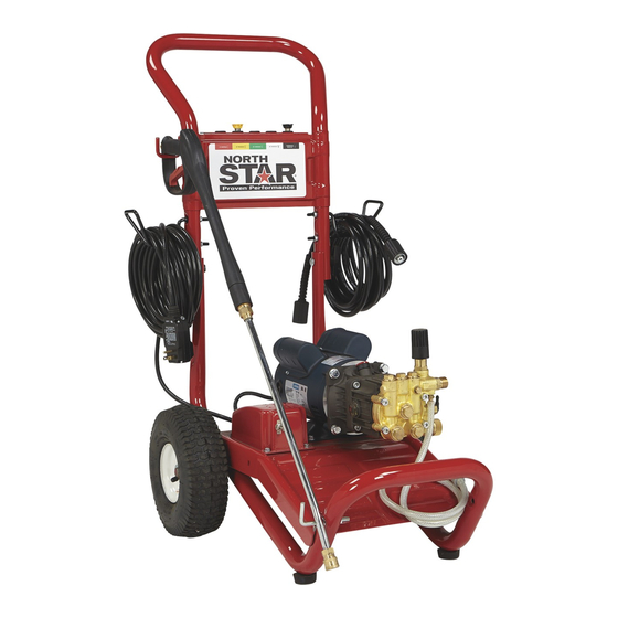
Owner's Manual
Pressure Washer:
surfaces with high pressure water.
Any Questions, Comments, Problems or Parts Orders
Call NorthStar Product Support 1-800-270-0810
T M
Read this manual.
Serious injury or death can result if safety instructions are not followed.
Pump is shipped with oil.
- Remove shipping tape from pump oil fill cap. (Cat Pumps)
- Remove shipping plug and install vented fill cap. (Comet Pumps)
- See pump oil cap section of this manual.
Closely inspect all components.
-If you have damaged components: Contact the freight company that
delivered the unit and file a claim.
-If you have missing components: Contact Customer Service at
1-800-270-0810.
M1573001A
Item Numbers:
Machine that cleans dirty
WARNING
1573001,1573011
1573021
Advertisement
Table of Contents

Related Manuals for North Star M1573001A


Summary of Contents for North Star M1573001A
-
Page 1: Pressure Washer
-If you have damaged components: Contact the freight company that delivered the unit and file a claim. -If you have missing components: Contact Customer Service at 1-800-270-0810. Any Questions, Comments, Problems or Parts Orders Call NorthStar Product Support 1-800-270-0810 M1573001A Item Numbers: Machine that cleans dirty WARNING 1573001,1573011 1573021... - Page 2 Hazard Signal Word Definitions...
-
Page 3: Table Of Contents
Important Safety Instructions………………………... 4-5 Warning Label Locations……………………………... 6 Assembly Instructions……………………………………. 7-9 Machine Component Identification……………………… 10 Pump Oil Cap and Pump Component Identification….. 11 Operation Instructions………………………………... 11-15 Water Supply………………………………………... 11 Start-Up/Shut-Down Instructions………………….. 12 Spray Gun Safety Lock and Attaching the Lance.. 13 Installing Nozzles and Quick Connect hoses…….. -
Page 4: Important Safety Instructions
WARNING -Risk of Injection or Injury to Persons - Do Not Direct Discharge Stream at Persons. - Do not use a hose if exterior damage is evident. -Risk of explosion. - Do not spray flammable liquids. - Do not operate in a flammable environment. -
Page 5: Grounding Instructions
GROUND FAULT CIRCUIT INTERRUPTER PROTECTION This pressure washer is provided with a ground fault circuit interrupter (GFCI) built into the plug of the power supply cord. This device provides additional protection from the risk of electric shock. Should replacement of the plug or cord become necessary, use only identical replacement parts that include GFCI protection. -
Page 6: Warning Label Locations
SHUT-DOWN INSTRUCTIONS START-UP INSTRUCTIONS 1. Attach garden hose. 1. Turn motor OFF. 2. Attach pressure hose. 2. Unplug the power cord. 3. Attach gun and lance. 3. Turn water supply OFF. 4. Turn water supply ON. 4. Squeeze trigger to 5. -
Page 7: Assembly Instructions
Assembly Instructions I.) Unpack Your pressure washer is shipped in one box. Separate and identify the components found in both boxes. Pressure Hose Handle Motor/Pump/Base Assembly Lance Spray Gun Hardware Bag * Figures shown are for representation only. Actual components will vary by model. - Page 8 Assembly Instructions I.) Hardware Bag Carriage Bolt - Qty 2 Flange Nut – Qty 8 Vented fill cap Part # 82233 Part # 82019 (1573001 only) T-Handle – Qty 2 Part # 38578 Gun Hook – Qty 2 Part # 38509 Hose Hook –...
-
Page 9: Assembly Instructions
Assembly Instructions III.) Handle Assembly 1.) Attach handle to base with two carriage bolts and t-handle knobs. 2.) Spin a flange nut backwards onto two hose hooks and each gun hook. (see hook detail) 3.) Mount the hose hooks and gun hooks onto the handle as shown. 4.) Insert grommets into the holes on the handle nameplate. -
Page 10: Machine Component Identification
Machine Component Identification * Components shown are for representation only. Actual components will vary by model. 1.) Handle. Designed for easy cart movement. 2.) Hose Hook. Store hose on hook. 3.) Pressure Hose. Attach quick couplers to gun and water outlet. 4.) Chemical Hose. -
Page 11: Pump Oil Cap And Pump Component Identification
4.) Never use a reservoir tank as a water source. Drawing water out of a tank may cause pump cavitation and damage to your pump. This pressure washer is designed for a pressurized water source such as a city water faucet. However, the water source pressure must not exceed 115 psi (8 bar). -
Page 12: Start-Up/Shut-Down Instructions
Operation Instructions START-UP INSTRUCTIONS 1. Attach garden hose. 2. Attach pressure hose. 3. Attach gun and lance. 4. Turn water supply ON. 5. Squeeze trigger to purge air from pump. 6. Insert nozzle. 7. Plug in power cord 8. Reset the GFCI button on the cord 9. -
Page 13: Spray Gun Safety Lock And Attaching The Lance
Operation Instructions Spray Gun Safety Lock When not spraying, use the spray gun safety lock to prevent accidental high pressure discharge. spray gun spray gun safety lock * Note: Depending on model, gun may appear differently. Attaching the Lance spin-on coupler lance Tighten spin-on coupler hand tight. -
Page 14: Installing Nozzles And Quick Connect Hoses
Installing Nozzles To install a nozzle pull back the collar and push the nozzle into the coupler. Once the connection is made, pull on the nozzle to make sure it is secure. nozzle collar completely pushed out. CORRECT Flying objects. Make sure nozzle is secure before squeezing trigger. -
Page 15: Applying Chemicals
Applying Chemicals 1.) Install the black nozzle when applying chemicals onto the cleaning surface. 2.) Start the pressure washer according to the start-up instructions. 3.) Submerge the chemical hose in cleaning solution. (See Pump Component Identification section for chemical injector location.) 4.) Squeeze the spray gun trigger. -
Page 16: Maintenance And Storage
Maintenance Mode Before performing any maintenance on the pressure washer, it must be placed in maintenance mode. 1.) Turn off motor and unplug cord. 2.) Turn off water supply. 3.) Squeeze trigger to relieve system pressure. Maintenance Schedule What to Check... -
Page 17: Pump Oil Change
Pump Oil Change 1.) Place a suitable container below the pump to catch the used oil, then remove the oil fill cap and oil drain plug. 2.) Allow the used oil to drain completely, then reinstall the drain plug and tighten securely. 3.) Please dispose of used oil in a manner that is compatible with the environment. -
Page 18: Winter Storage
Maintenance and Storage Winter Storage Protect your pump, hose and gun from freezing. Items needed: 12” piece of garden hose or equivalent, funnel and RV antifreeze (approximately 6 oz.) 1.) Follow the storage instructions listed above. 2.) Make sure the motor start switch is OFF. 3.) Attach the garden hose with funnel to the pump inlet (see illustration). -
Page 19: Troubleshooting
Problem Motor will not start Low/Surging pressure or no water flow No chemical injection Cause A- Tripped GFCI cord B- Tripped motor relay C- Insufficient water supply D- Plugged pump inlet filter E- Wrong nozzle F- Plugged nozzle G- Worn nozzle H- Leak in pressure hose I- Wrong nozzle J- Back pressure from extra long discharge hose... -
Page 20: Specifications
1573001 PSI (bar) GPM (l/min) Max Water Temp Dimensions 34” x 21” x 38” (864mm x 534mm x 965mm) L x W x H Weight 1573021 PSI (bar) GPM (l/min) Max Water Temp Dimensions 34” x 21” x 38” (864mm x 534mm x 965mm) L x W x H Weight Specifications... - Page 21 Wiring Diagram...
-
Page 22: Parts Explosions
Part Explosion M1573001 Rev - A... - Page 23 Part Explosion M1573001 Rev - A ITEM # PART # DESCRIPTION 38509 Threaded Gun Hook 778065 NorthStar Decal 35198 7/16 ID Grommet 778059 Handle 38510 Threaded Hose Hook 38578 T-Handle Knob 778125 Base 778129 2278 Tire Wheel Assembly 305200 Wheel Retainer 38524 5/16 x 25' Gray Hose 777915...
- Page 24 *This page is to help ensure that the factory includes all components in the manual bag.