
Related Manuals for ELNA 6005 heirloom edition


Summary of Contents for ELNA 6005 heirloom edition
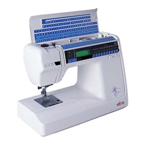
- Page 1 PDFMAILER.DE Elna 6005 Heirloom Edition SERVICE MANUAL 11/99 Printed in Switzerland 395902-42...
-
Page 2: Table Of Contents
PDFMAILER.DE CONTENTS WIRING AND ELECTRONIC CHECK Wiring diagram General trouble shooting procedure What to do when 3 - 5 Electronic quick check 6 - 7 SERVICE ACCESS Face cover Top cover Belt cover Base plate Bed cover Front cover Rear cover MECHANICAL ADJUSTMENT Needle centring Needle bar height... -
Page 3: Wiring Diagram
PDFMAILER.DE Wiring Diagram NAME OF ELECTRONIC PARTS AND WIRING Each connector should be connected as follows A: THREAD TENSION SWITCH G: ZIGZAG STEPPING MOTOR B: BUTTONHOLE SENSOR H: DC MOTOR C: UPPER SHAFT SENSOR I: F-BOARD D: SEWING LIGHT J: K-BOARD E: C-BOARD K: RECEPTACLE (SECONDARY) FEED STEPPING MOTOR... -
Page 4: General Trouble Shooting Procedure
PDFMAILER.DE GENERAL TROUBLE SHOOTING PROCEDURE MACHINE DOESN'T WORK WELL... -
Page 5: What To Do When
PDFMAILER.DE WHAT TO DO WHEN CONDITION CAUSE HOW TO FIX REFERENCE Skipping stitches. 1. Needle is not inserted 1. Insert the needle properly. properly. 2. Needle is bent or worn. 2. Change the needle. 3. Incorrectly threaded. 3. Retread. 4. Needle or thread is 4. - Page 6 PDFMAILER.DE WHAT TO DO WHEN CONDITION CAUSE HOW TO FIX REFERENCE 5. Needle breaks. 1. Needle is hitting the See mechanical adjustment needle plate. "Needle position". 2. Needle is bent or worn. Change the needle. 3. Needle is hitting the See mechanical adjustment hook.
- Page 7 PDFMAILER.DE DIAGNOSIS CHART A Operation 1 Be cautious of sudden running of the machine when turning on the power switch. If nothing is happened on the machine when the power switch is turned on, turn off the power switch and check the following points: Step 1: Make sure that all of the connectors are connected properly.
-
Page 8: Electronic Quick Check
PDFMAILER.DE DIAGNOSIS CHART Step Test operation Correct condition Defect condition Step LCD, LED Turn on the power LCD shows (Special If the machine does not go to test. switch while Mode). Test mode, replace the pressing LCD shows (Self-Check following parts in order and “REVERSE”, AUO- Start). - Page 9 PDFMAILER.DE “Reverse” Key. DIAGNOSIS CHART Step Test operation Correct condition Defect condition Step Foot Depress the foot Buzzer sounds and LCD If not working properly, replace control. control as far as it shows (controller). the following parts in order will go. Then Buzzer sounds when the and recheck.
-
Page 10: Face Cover
PDFMAILER.DE FACE AND TOP COVER FACE COVER To remove 1. Remove the cap A and set screw B. 2. Remove the face plate D while pulling it toward you so that face plate hook C is released. To attach 1. Attach the face plate. 2. -
Page 11: Belt Cover
PDFMAILER.DE BELT COVER To remove 1. Remove the cap A 2. Remove the screws B and D 3. Lift up the handle F and loosen the screws E To attach 1. Attach the belt cover C with the screws B, D and E 2. -
Page 12: Base Plate
PDFMAILER.DE BASE PLATE AND BED COVER Base plate To remove Remove the screw A and 4 screws B Remove the base plate C. To attach Reverse this procedure Bed cover To remove Remove the 2 screws D Remove the bed cover E To attach Move the drop lever F to the left and attach the bed cover with the screws D. -
Page 13: Front Cover
PDFMAILER.DE FRONT COVER To remove Remove the face cover, top cover, belt cover and bed cover (see pages 8, 9, and 10). Remover the screw A and loosen the screws B, C, D, E, F and G. Pull out the connector H and remove the front cover K. To attach Reverse this procedure... -
Page 14: Rear Cover
PDFMAILER.DE REAR COVER To remove Remove the face cover, top cover, belt cover and bed cover (see pages 8, 9, and 10). Loosen the screws A, B, C and D. Remove the cap E and remove the screw F. Remove the rear cover while pulling it toward you and pushing it to the left. Unhook the projection G and twist the rear cover to clear the presser bar lifter area. -
Page 15: Needle Centring
PDFMAILER.DE NEEDLE CENTRING When selecting pattern N°. 1, the needle should be in centre position of needle slot in the needle plate, or when the needle swing is in maximum zigzag width, the distance between both sides of needle slot in the needle plate and the needle positions should be equal. If not, adjust as follows: Turn on the power switch. -
Page 16: Needle Bar Height
PDFMAILER.DE NEEDLE BAR HEIGHT A regular needle #14 should be used for this adjustment. The distance between the upper edge of needle eye and the tip of shuttle hook should be in the range of 1.6 - 2.0 mm when the tip of shuttle hook meets the right side of the needle as the needle is moved up from its left and lowest position by turning the handwheel toward you. -
Page 17: Hook And Feed Timing
PDFMAILER.DE HOOK AND FEED TIMING A regular needle B #14 should be used for this adjustment. Select pattern 2. Turn the handwheel toward you to position the needle bar from its lowest position, moving up approximately 2,30 mm to 2,60 mm. At this position, the tip of the hook should meet the right side of the needle. 1. -
Page 18: Clearance
PDFMAILER.DE CLEARANCE The clearance between the needle and the point of hook should be +0.05 –0.1 mm. If not, adjust as follows: Remove the needle plate and bobbin case. Replace the needle with master needle D. Turn on the power switch and select pattern 2. Loosen the set screws A, B, C and slightly loosen the hinge screw C. -
Page 19: Backlash Of Hook Drive Gear And Lower Shaft Gear
PDFMAILER.DE BACKLASH OF HOOK DRIVE GEAR AND LOWER SHAFT GEAR The backlash of the gears should be smooth and should be less than 0.8 mm when the point of the hook is under the feed dog. To check: Turn the power switch off. Remove the needle plate and bobbin holder. -
Page 20: Feed Dog Height
PDFMAILER.DE FEED DOG HEIGHT The highest position of the feed dog should be between 0.80 and 0.90 mm from the surface of the needle plate when the pressure dial is set at 3 and the presser foot is lowered. Set the pressure dial at 3 and lower the presser foot. Turn on the power switch. -
Page 21: Needle Bar Swing Sensor
PDFMAILER.DE NEEDLE BAR SWING / SENSOR NOTE: When the machine is set to maximum zigzag width, the needle should start to swing laterally between 6.3 to 7.5 mm above the needle plate. 1. Remove the top cover (see page 1). 2. -
Page 22: Upper And Lower Tension
PDFMAILER.DE UPPER AND LOWER TENSION Check: Set the upper thread tension dials F to 3. The standard upper tension should be 75 - 90g when pulling the thread (cotton thread 50/3) in direction C. Adjust the upper tension: 1. Set the thread tension dial F to 3. 2. -
Page 23: Stretch Stitch Feed Balance
PDFMAILER.DE STRETCH STITCH FEED BALANCE When pattern “8” is sewn with the feed balancing dial at the standard setting mark, figure D, the stitch pattern should be as shown below. Turn on the power switch while pushing the reverse button, and then select the pattern No. -
Page 24: Buttonhole
PDFMAILER.DE BUTTONHOLE A) BUTTONHOLE LEVER GUIDE 1. Attach the automatic buttonhole foot R. Loosen the set screw A and leave the clearance of 2.9 mm between the spring holder C and slider B by moving the buttonhole lever guide C in this condition the buttonhole lever E should touch the spring holder C slightly. -
Page 25: Presser Bar Height And Alignment
PDFMAILER.DE PRESSER BAR HEIGHT AND ALIGNMENT To check: Raise the presser foot lever B. The distance between the zigzag foot A and the needle plate C should be 6.0 mm. If the height is greater or less than 6 mm, adjust as follows. To adjust: Remove the face cover (see page 8). -
Page 26: Threader Plate
PDFMAILER.DE THREADER PLATE When the hook of the threader plate is damaged, change or adjust the part as follows. To change the threader plate: Raise the needle to its highest position and lower the threader knob A to its lowest position. Loosen the screw B and remove the threader plate (Fig. -
Page 27: C-Board And Fuse
PDFMAILER.DE C-BOARD AND FUSE To remove: Remove the front cover (see page 11). Take off the rear cover (see page 12). Pull out 4 connectors D, E, F and G. Remove the 3 screws A. 5. Take off the c-board case unit B. To attach: Reverse this procedure. -
Page 28: Transformer
PDFMAILER.DE TRANSFORMER To remove: Remove the front cover (see page 11). Remove the A-board (see page 28). Remove the C-board case (see page 25). Detach the connectors A and B. Remove the screws C and D. Take out the transformer F. To attach: Set the rear side of the transformer F on the supporter E. -
Page 29: Receptacle
PDFMAILER.DE RECEPTACLE To remove: Remove the front cover and the rear cover (see page 11 and 12). Remove the C-Board case unit C (see page 25). Move it so that the connectors can be pulled out. Pull out connectors A and B. Remove the 2 screws E. -
Page 30: A-Board
PDFMAILER.DE A – BOARD To remove: Remove the front cover (see page 11). Pull out the 8 connectors A, B, C, D, E, F, G and H. Remove the 3 screws J. Take off the A-Board. Install a new A-Board and reverse this procedure. -
Page 31: K And F-Board
PDFMAILER.DE K AND F BOARD To remove: Remove the front cover (see page 11). Remove the 7 screws for the printed circuit board F and 2 screws for the printed circuit board K. Pull out the connectors of the printed circuit boards F or K, and then remove the printed circuit boards F or K. -
Page 32: Dc Motor
PDFMAILER.DE DC MOTOR To remove: Remove the front cover (see page 11). Move the front cover so that you can pull out the driving motor connector. Remove the receptacle (See page 27). Remove the belt. Removes screw A and remove cord guide B. Pull out the motor connector from the A-board. -
Page 33: Buttonhole
PDFMAILER.DE BUTTONHOLE SENSOR To remove: Remove the front cover (see page 11). Move it so that the connectors can be pulled out. Remove the screw A, then remove the buttonhole sensor B from the sensor plate C. Pull out the connector of buttonhole sensor D from the k-board. Pull out the cord of buttonhole sensor from the cord guide E and then remove the buttonhole sensor B. -
Page 34: Upper Shaft Sensor
PDFMAILER.DE UPPER SHAFT SENSOR To remove: Remove the front cover (see page 11). Pull out the 8 connectors from the A-board. Remove the 3 screws A and remove the A circuit board E. Push the holders B and remove the upper shaft sensor C. To attach: 1. -
Page 35: Zigzag Stepping Motor
PDFMAILER.DE ZIGZAG STEPPING MOTOR To remove: Remove the C-board case unit and receptacle unit (see page 25 and 27). Remove the 3 screws A and the A-board setting plate. Remove the 2 screws B, 2 screws C and remove the motor D. To attach: Reverse this procedure. -
Page 36: Feed Stepping Motor
PDFMAILER.DE FEED STEPPING MOTOR To remove: Remove the front cover (see page 11). Remove the receptacle unit (see page 27). Pull out the feed stepping motor connector from the A-circuit board. Remove the snap ring B and the 2 screws A. Remove the feed stepping motor C together with feed rod D.