Nokia 300 Service Manual
Hide thumbs
Also See for 300:
- User manual (143 pages) ,
- Service manual (20 pages) ,
- User manual (74 pages)

Related Manuals for Nokia 300


Summary of Contents for Nokia 300
- Page 1 Nokia Customer Care Service Manual RM-781 (Nokia 300; Nokia 3000) Mobile Terminal Part No: (Issue 1) COMPANY CONFIDENTIAL Copyright © 2011 Nokia. All rights reserved.
- Page 2 RM-781 Amendment Record Sheet Amendment Record Sheet Amendment No Date Inserted By Comments Issue 1 10/2011 Jeff Zhao Page ii COMPANY CONFIDENTIAL Issue 1 Copyright © 2011 Nokia. All rights reserved.
- Page 3 Nokia operates a policy of continuous development. Nokia reserves the right to make changes and improvements to any of the products described in this document without prior notice. Under no circumstances shall Nokia be responsible for any loss of data or income or any special, incidental, consequential or indirect damages howsoever caused.
- Page 4 WCDMA networks and cause problems to 3G cellular phone communication in a wide area. • During testing never activate the GSM or WCDMA transmitter without a proper antenna load, otherwise GSM or WCDMA PA may be damaged. Page iv COMPANY CONFIDENTIAL Issue 1 Copyright © 2011 Nokia. All rights reserved.
- Page 5 Use only approved accessories and batteries. Do not connect incompatible products. CONNECTING TO OTHER DEVICES When connecting to any other device, read its user’s guide for detailed safety instructions. Do not connect incompatible products. Issue 1 COMPANY CONFIDENTIAL Page v Copyright © 2011 Nokia. All rights reserved.
- Page 6 All of the above suggestions apply equally to the product, battery, charger or any accessory. Page vi COMPANY CONFIDENTIAL Issue 1 Copyright © 2011 Nokia. All rights reserved.
- Page 7 RM-781 ESD protection ESD protection Nokia requires that service points have sufficient ESD protection (against static electricity) when servicing the phone. Any product of which the covers are removed must be handled with ESD protection. The SIM card can be replaced without ESD protection if the product is otherwise ready for use.
- Page 8 Batteries' performance is particularly limited in temperatures well below freezing. Do not dispose of batteries in a fire! Dispose of batteries according to local regulations (e.g. recycling). Do not dispose as household waste. Page viii COMPANY CONFIDENTIAL Issue 1 Copyright © 2011 Nokia. All rights reserved.
- Page 9 Our policy is of continuous development; details of all technical modifications will be included with service bulletins. While every endeavour has been made to ensure the accuracy of this document, some errors may exist. If any errors are found by the reader, NOKIA MOBILE PHONES Business Group should be notified in writing/e- mail. Please state: •...
- Page 10 RM-781 Company policy (This page left intentionally blank.) Page x COMPANY CONFIDENTIAL Issue 1 Copyright © 2011 Nokia. All rights reserved.
- Page 11 RM-781 Nokia 300; Nokia 3000 Service Manual Structure Nokia 300; Nokia 3000 Service Manual Structure 1 General information 2 Service Devices and Service Concepts 3 BB Troubleshooting and Manual Tuning Guide 4 Cellular RF troubleshooting 5 System Module 6 Other peripherals (ie. CWS)
- Page 12 RM-781 Nokia 300; Nokia 3000 Service Manual Structure (This page left intentionally blank.) Page xii COMPANY CONFIDENTIAL Issue 1 Copyright © 2011 Nokia. All rights reserved.
- Page 13 Nokia Customer Care 1 — General information Issue 1 COMPANY CONFIDENTIAL Page 1 – 1 Copyright © 2011 Nokia. All rights reserved.
- Page 14 RM-781 General information (This page left intentionally blank.) Page 1 – 2 COMPANY CONFIDENTIAL Issue 1 Copyright © 2011 Nokia. All rights reserved.
-
Page 15: Table Of Contents
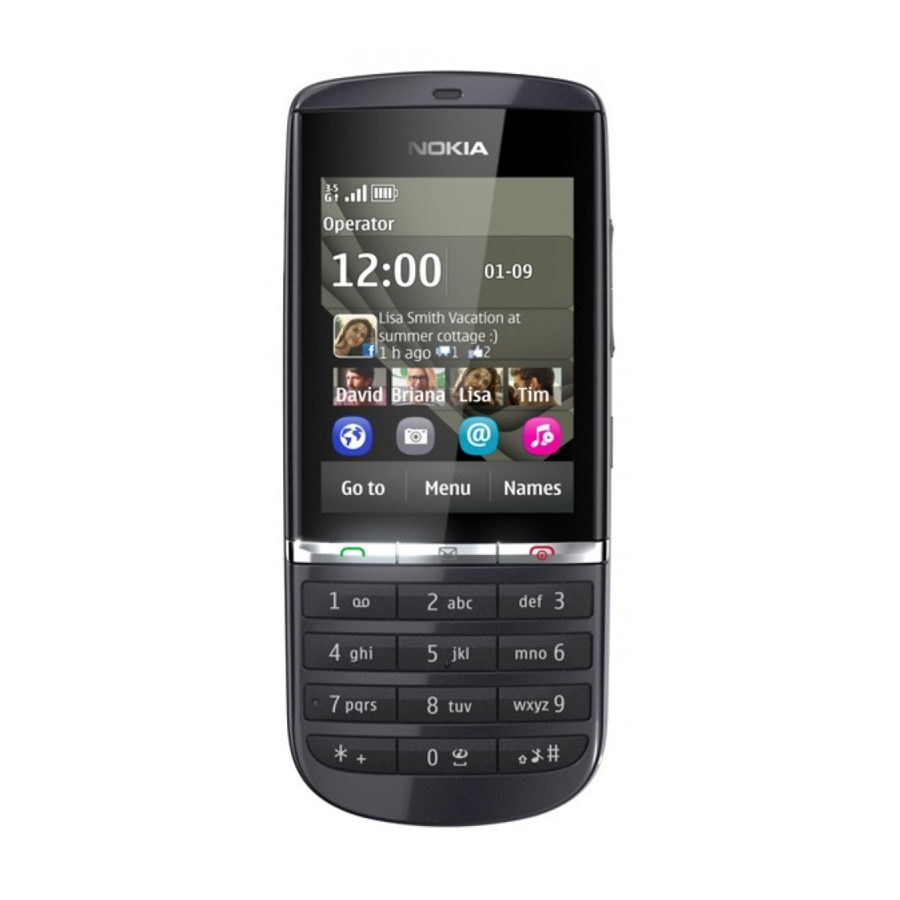
Main RF characteristics for GSM850/900/1800/1900 and WCDMA VIII/V/II/I phones........ 1–6 Battery endurance............................1–8 Environmental conditions ..........................1–8 List of Figures Figure 1 RM–781 (Nokia 300/Nokia 3000) product picture ................1–5 Issue 1 COMPANY CONFIDENTIAL Page 1 – 3 Copyright © 2011 Nokia. All rights reserved. - Page 16 RM-781 General information (This page left intentionally blank.) Page 1 – 4 COMPANY CONFIDENTIAL Issue 1 Copyright © 2011 Nokia. All rights reserved.
-
Page 17: Product Selection
RM-781 General information Product selection Figure 1 RM–781 (Nokia 300/Nokia 3000) product picture Phone features Hardware features • 3GPP: Rel.6 • WCDMA packet data: HSUPA cat 5 up to 2 Mbps; HSDPA cat 9 up to 10.2 Mbp • Speech Codecs: NB-AMR, WB-AMR, HR, FR, EFR •... -
Page 18: Technical Specifications
WCDMA VIII (900): 925 - 960 MHz WCDMA V (850): 869 - 894 MHz WCDMA II (1900): 1930 - 1990 MHz WCDMA I (2100): 2110 - 2170 MHz Page 1 – 6 COMPANY CONFIDENTIAL Issue 1 Copyright © 2011 Nokia. All rights reserved. - Page 19 WCDMA VIII (900): 152 WCDMA V (850): 108 WCDMA II (1900): 289 WCDMA I (2100): 277 Channel spacing 200 kHz (WCDMA V and II 100/200 kHz) Issue 1 COMPANY CONFIDENTIAL Page 1 – 7 Copyright © 2011 Nokia. All rights reserved.
-
Page 20: Battery Endurance
Condensed or dripping water may cause intermittent malfunctions. Protection against dripping water has to be implemented in (enclosure) mechanics. Continuous dampness will cause permanent damage to the module. Page 1 – 8 COMPANY CONFIDENTIAL Issue 1 Copyright © 2011 Nokia. All rights reserved. - Page 21 Nokia Customer Care 2 — Service Devices and Service Concepts Issue 1 COMPANY CONFIDENTIAL Page 2 – 1 Copyright © 2011 Nokia. All rights reserved.
- Page 22 RM-781 Service Devices and Service Concepts (This page left intentionally blank.) Page 2 – 2 COMPANY CONFIDENTIAL Issue 1 Copyright © 2011 Nokia. All rights reserved.
- Page 23 2–11 DAU-9S ............................... 2–11 PCS-1 ................................2–12 XRS-6................................2–12 Service concepts ..............................2–12 Note: ................................2–12 List of Tables Table 1 Attenuation values ..........................2–10 Issue 1 COMPANY CONFIDENTIAL Page 2 – 3 Copyright © 2011 Nokia. All rights reserved.
- Page 24 RM-781 Service Devices and Service Concepts (This page left intentionally blank.) Page 2 – 4 COMPANY CONFIDENTIAL Issue 1 Copyright © 2011 Nokia. All rights reserved.
-
Page 25: Service Devices
RM-781. For the correct use of the service devices, and the best effort of workbench setup, please refer to various concepts. MJ-300 Module jig Module jig MJ-300 can be used for flashing via USB and RF, battery and system testing. The main functions are: • Powering with external power •... -
Page 26: General Devices
Interface for CU-4 control unit SS-227 is designed for regional Central Services to be able to use CU-4 with MJ-300 module jig. With SS-227, CU-4 can be used for battery testing. The main functions of SS-227 are: • CU-4 interface adapter to MJ-300 •... - Page 27 4 Connect an FBUS cable (if necessary). 5 Start Phoenix service software. Note: Phoenix enables CU-4 regulators via USB when it is started. Reconnecting the power supply requires a Phoenix restart. Issue 1 COMPANY CONFIDENTIAL Page 2 – 7 Copyright © 2011 Nokia. All rights reserved.
-
Page 28: Fps-21
In order to access the SD memory card slots inside FPS-21, the prommer needs to be opened by removing the front panel, rear panel and heatsink from the prommer body. Page 2 – 8 COMPANY CONFIDENTIAL Issue 1 Copyright © 2011 Nokia. All rights reserved. - Page 29 • Installation and warranty information SRT-6 Opening tool SRT-6 is used to open phone covers. Note: The SRT-6 is included in the Nokia Standard Toolkit. SS-46 Interface adapter SS-46 acts as an interface adapter between the flash adapter and FPS-20/FPS-21.
-
Page 30: Cables
RF tuning cable Product-specific adapter cable for RF tuning. • Table 1 Attenuation values Band Attenuation Rx/Tx GSM+WCDMA 850/900 0.2...0.3 dB GSM+WCDMA 1800/1900 0.3...0.4 dB Page 2 – 10 COMPANY CONFIDENTIAL Issue 1 Copyright © 2011 Nokia. All rights reserved. -
Page 31: Ca-31D
The MBUS cable DAU-9S has a modular connector and is used, for example, between the PC's serial port and module jigs, flash adapters or docking station adapters. Note: Docking station adapters valid for DCT4 products. Issue 1 COMPANY CONFIDENTIAL Page 2 – 11 Copyright © 2011 Nokia. All rights reserved. -
Page 32: Service Concepts
SMA to N-Connector approximately 610 mm. Attenuation for: • GSM850/900: 0.3+-0.1 dB • GSM1800/1900: 0.5+-0.1 dB • WCDMA: 0.6+-0.1dB Service concepts Note: For service concepts please refer to SR993. Page 2 – 12 COMPANY CONFIDENTIAL Issue 1 Copyright © 2011 Nokia. All rights reserved. - Page 33 Nokia Customer Care 3 — BB Troubleshooting and Manual Tuning Guide Issue 1 COMPANY CONFIDENTIAL Page 3 – 1 Copyright © 2011 Nokia. All rights reserved.
- Page 34 RM-781 BB Troubleshooting and Manual Tuning Guide (This page left intentionally blank.) Page 3 – 2 COMPANY CONFIDENTIAL Issue 1 Copyright © 2011 Nokia. All rights reserved.
-
Page 35: Table Of Contents
Earpiece troubleshooting ........................3–44 IHF troubleshooting ..........................3–45 Microphone troubleshooting ........................3–46 Vibra troubleshooting........................... 3–47 Baseband manual tuning guide........................3–47 Energy management calibration ......................... 3–47 Issue 1 COMPANY CONFIDENTIAL Page 3 – 3 Copyright © 2011 Nokia. All rights reserved. - Page 36 Figure 6 Touch screen basic checks ........................3–29 Figure 7 Differential output waveform of the Ext_in_IHF_out out loop measurement when speaker is connected..............................3–40 Page 3 – 4 COMPANY CONFIDENTIAL Issue 1 Copyright © 2011 Nokia. All rights reserved.
-
Page 37: Baseband Self Tests In Phoenix
Always start the troubleshooting procedure by running the Phoenix self tests. If a test fails, please follow the diagram below. Dead or jammed device troubleshooting. If the phone is dead and you cannot perform the self tests, go to Issue 1 COMPANY CONFIDENTIAL Page 3 – 5 Copyright © 2011 Nokia. All rights reserved. - Page 38 RM-781 BB Troubleshooting and Manual Tuning Guide Troubleshooting flow Page 3 – 6 COMPANY CONFIDENTIAL Issue 1 Copyright © 2011 Nokia. All rights reserved.
-
Page 39: Power And Charging Troubleshooting
RM-781 BB Troubleshooting and Manual Tuning Guide Power and charging troubleshooting Dead or jammed device troubleshooting Troubleshooting flow - Page 1 of 2 Issue 1 COMPANY CONFIDENTIAL Page 3 – 7 Copyright © 2011 Nokia. All rights reserved. - Page 40 RM-781 BB Troubleshooting and Manual Tuning Guide Troubleshooting flow - Page 2 of 2 Page 3 – 8 COMPANY CONFIDENTIAL Issue 1 Copyright © 2011 Nokia. All rights reserved.
-
Page 41: Dynamo Charging Troubleshooting
RM-781 BB Troubleshooting and Manual Tuning Guide Dynamo charging troubleshooting Troubleshooting flow Issue 1 COMPANY CONFIDENTIAL Page 3 – 9 Copyright © 2011 Nokia. All rights reserved. -
Page 42: Power Key Troubleshooting
RM-781 BB Troubleshooting and Manual Tuning Guide Power key troubleshooting Troubleshooting flow Page 3 – 10 COMPANY CONFIDENTIAL Issue 1 Copyright © 2011 Nokia. All rights reserved. -
Page 43: General Voltage Checking Troubleshooting
RM-781 BB Troubleshooting and Manual Tuning Guide General voltage checking troubleshooting Troubleshooting flow - Page 1 of 2 Issue 1 COMPANY CONFIDENTIAL Page 3 – 11 Copyright © 2011 Nokia. All rights reserved. - Page 44 RM-781 BB Troubleshooting and Manual Tuning Guide Troubleshooting flow - Page 2 of 2 Page 3 – 12 COMPANY CONFIDENTIAL Issue 1 Copyright © 2011 Nokia. All rights reserved.
-
Page 45: General Power Checking
N2200 1.25 RF reference VCORE N2200 RAPU digital Can change due to RAPU version & SW VMEM N2200 microSD Disabled in sleep VDIGIMIC N2200 Digimic Issue 1 COMPANY CONFIDENTIAL Page 3 – 13 Copyright © 2011 Nokia. All rights reserved. -
Page 46: Charging Troubleshooting
RM-781 BB Troubleshooting and Manual Tuning Guide Charging troubleshooting Troubleshooting flow Page 3 – 14 COMPANY CONFIDENTIAL Issue 1 Copyright © 2011 Nokia. All rights reserved. -
Page 47: Usb Charging Troubleshooting
RM-781 BB Troubleshooting and Manual Tuning Guide USB charging troubleshooting Context For instructions regarding USB charging troubleshooting, see section USB charging troubleshooting (page 3– 0 Issue 1 COMPANY CONFIDENTIAL Page 3 – 15 Copyright © 2011 Nokia. All rights reserved. -
Page 48: Battery Current Measuring Fault Troubleshooting
RM-781 BB Troubleshooting and Manual Tuning Guide Battery current measuring fault troubleshooting Troubleshooting flow Page 3 – 16 COMPANY CONFIDENTIAL Issue 1 Copyright © 2011 Nokia. All rights reserved. -
Page 49: Interface Troubleshooting
RM-781 BB Troubleshooting and Manual Tuning Guide Interface troubleshooting SIM card troubleshooting Troubleshooting flow Issue 1 COMPANY CONFIDENTIAL Page 3 – 17 Copyright © 2011 Nokia. All rights reserved. - Page 50 RM-781 BB Troubleshooting and Manual Tuning Guide Page 3 – 18 COMPANY CONFIDENTIAL Issue 1 Copyright © 2011 Nokia. All rights reserved.
-
Page 51: Microsd Card Troubleshooting
RM-781 BB Troubleshooting and Manual Tuning Guide MicroSD card troubleshooting Troubleshooting flow Issue 1 COMPANY CONFIDENTIAL Page 3 – 19 Copyright © 2011 Nokia. All rights reserved. -
Page 52: Usb Troubleshooting
RM-781 BB Troubleshooting and Manual Tuning Guide USB troubleshooting USB data interface troubleshooting Troubleshooting flow - Page 1 of 2 Page 3 – 20 COMPANY CONFIDENTIAL Issue 1 Copyright © 2011 Nokia. All rights reserved. - Page 53 RM-781 BB Troubleshooting and Manual Tuning Guide Troubleshooting flow - Page 2 of 2 Issue 1 COMPANY CONFIDENTIAL Page 3 – 21 Copyright © 2011 Nokia. All rights reserved.
-
Page 54: Usb Charging Troubleshooting
RM-781 BB Troubleshooting and Manual Tuning Guide USB charging troubleshooting Troubleshooting flow Page 3 – 22 COMPANY CONFIDENTIAL Issue 1 Copyright © 2011 Nokia. All rights reserved. -
Page 55: User Interface Troubleshooting
(dirt, rust, mechanical damage, etc.) If the failure mode is not clear, start with the Keyboard test in Phoenix. Troubleshooting flow Issue 1 COMPANY CONFIDENTIAL Page 3 – 23 Copyright © 2011 Nokia. All rights reserved. -
Page 56: Keyboard Leds Troubleshooting
The device has a resistive touch screen user interface and has a traditional ITU-T keypad. The key components of the touch screen user interface are: Page 3 – 24 COMPANY CONFIDENTIAL Issue 1 Copyright © 2011 Nokia. All rights reserved. -
Page 57: Proximity Sensor Troubleshooting
Troubleshooting flow Figure 2 Proximity sensor troubleshooting - part 1 Issue 1 COMPANY CONFIDENTIAL Page 3 – 25 Copyright © 2011 Nokia. All rights reserved. - Page 58 RM-781 BB Troubleshooting and Manual Tuning Guide Figure 3 Proximity sensor troubleshooting - part 2 Page 3 – 26 COMPANY CONFIDENTIAL Issue 1 Copyright © 2011 Nokia. All rights reserved.
-
Page 59: Resistive Touch Screen Troubleshooting
RM-781 BB Troubleshooting and Manual Tuning Guide Resistive touch screen troubleshooting Troubleshooting flow Figure 4 Resistive touch screen troubleshooting Issue 1 COMPANY CONFIDENTIAL Page 3 – 27 Copyright © 2011 Nokia. All rights reserved. - Page 60 RM-781 BB Troubleshooting and Manual Tuning Guide Figure 5 Touch controller basic checks Page 3 – 28 COMPANY CONFIDENTIAL Issue 1 Copyright © 2011 Nokia. All rights reserved.
- Page 61 RM-781 BB Troubleshooting and Manual Tuning Guide Figure 6 Touch screen basic checks Issue 1 COMPANY CONFIDENTIAL Page 3 – 29 Copyright © 2011 Nokia. All rights reserved.
-
Page 62: Display Module Troubleshooting
Total Combined Not allowed. defect counts Two single dot defects that are within 5 mm of each other should be interpreted as combined dot defect. Page 3 – 30 COMPANY CONFIDENTIAL Issue 1 Copyright © 2011 Nokia. All rights reserved. - Page 63 APE ID). 3. Proceed to the display fault troubleshooting flowchart. Phoenix to find the detailed fault mode. Use the Display Test tool in Issue 1 COMPANY CONFIDENTIAL Page 3 – 31 Copyright © 2011 Nokia. All rights reserved.
-
Page 64: Display Fault Troubleshooting
RM-781 BB Troubleshooting and Manual Tuning Guide Display fault troubleshooting Troubleshooting flow Page 3 – 32 COMPANY CONFIDENTIAL Issue 1 Copyright © 2011 Nokia. All rights reserved. -
Page 65: Display Backlight Troubleshooting
Bad conditions often cause bad pictures. Therefore, the camera operation has to be checked in constant conditions or by using a second, known-to-be-good Nokia device as reference. Image quality is hard to measure quantitatively, and the difference between a good and a bad picture can be small. Some training or experience may be needed to detect what is actually wrong. -
Page 66: Camera Troubleshooting
• The image may be blurred, though it does not show in the viewfinder • Analyse the picture from your PC monitor, full colour setting is recommended • If possible, compare with a picture of the same motive taken with a similar Nokia device Page 3 – 34... -
Page 67: Camera Troubleshooting
RM-781 BB Troubleshooting and Manual Tuning Guide Camera troubleshooting Troubleshooting flow Issue 1 COMPANY CONFIDENTIAL Page 3 – 35 Copyright © 2011 Nokia. All rights reserved. -
Page 68: Camera Baseband Troubleshooting
RM-781 BB Troubleshooting and Manual Tuning Guide Camera baseband troubleshooting Troubleshooting flow Page 3 – 36 COMPANY CONFIDENTIAL Issue 1 Copyright © 2011 Nokia. All rights reserved. -
Page 69: Camera No Recognizable Viewfinder Image Troubleshooting
RM-781 BB Troubleshooting and Manual Tuning Guide Camera no recognizable viewfinder image troubleshooting Troubleshooting flow Issue 1 COMPANY CONFIDENTIAL Page 3 – 37 Copyright © 2011 Nokia. All rights reserved. -
Page 70: Camera Bad Image Quality Troubleshooting
RM-781 BB Troubleshooting and Manual Tuning Guide Camera bad image quality troubleshooting Troubleshooting flow Page 3 – 38 COMPANY CONFIDENTIAL Issue 1 Copyright © 2011 Nokia. All rights reserved. -
Page 71: Audio Troubleshooting
The following equipment is needed for the tests: • Oscilloscope • Function generator (sine waveform) • Phoenix service software and NCS (Nokia Care Suite) • Battery voltage 3.7V Test procedure Audio can be tested using the Phoenix audio routings option. These different audio loop paths can be activated: •... - Page 72 2kHz. Figure 7 Differential output waveform of the Ext_in_IHF_out out loop measurement when speaker is connected. Page 3 – 40 COMPANY CONFIDENTIAL Issue 1 Copyright © 2011 Nokia. All rights reserved.
-
Page 73: Internal Earpiece Troubleshooting
RM-781 BB Troubleshooting and Manual Tuning Guide Internal earpiece troubleshooting Troubleshooting flow Issue 1 COMPANY CONFIDENTIAL Page 3 – 41 Copyright © 2011 Nokia. All rights reserved. -
Page 74: Internal Microphone Troubleshooting
RM-781 BB Troubleshooting and Manual Tuning Guide Internal microphone troubleshooting Troubleshooting flow Page 3 – 42 COMPANY CONFIDENTIAL Issue 1 Copyright © 2011 Nokia. All rights reserved. -
Page 75: Internal Handsfree (Ihf) Troubleshooting
IHF speaker radiates from the sound hole located on the backside on the bottom part of the phone. The inlet for the microphone can be found in the keymat area. Issue 1 COMPANY CONFIDENTIAL Page 3 – 43 Copyright © 2011 Nokia. All rights reserved. -
Page 76: Earpiece Troubleshooting
The phone should be dry and clean, and no objects must be located in such a way that they close any of the holes. Earpiece troubleshooting Troubleshooting flow Page 3 – 44 COMPANY CONFIDENTIAL Issue 1 Copyright © 2011 Nokia. All rights reserved. -
Page 77: Ihf Troubleshooting
RM-781 BB Troubleshooting and Manual Tuning Guide IHF troubleshooting Troubleshooting flow Issue 1 COMPANY CONFIDENTIAL Page 3 – 45 Copyright © 2011 Nokia. All rights reserved. -
Page 78: Microphone Troubleshooting
RM-781 BB Troubleshooting and Manual Tuning Guide Microphone troubleshooting Troubleshooting flow Page 3 – 46 COMPANY CONFIDENTIAL Issue 1 Copyright © 2011 Nokia. All rights reserved. -
Page 79: Vibra Troubleshooting
• Supply 12V DC from an external power supply to CU-4 to power up the phone. • The phone must be connected to a CU-4 control unit with a product-specific flash adapter. Issue 1 COMPANY CONFIDENTIAL Page 3 – 47 Copyright © 2011 Nokia. All rights reserved. - Page 80 Write and/or repeat the procedure again. Energy Management Calibration window. 10. To end the procedure, close the Page 3 – 48 COMPANY CONFIDENTIAL Issue 1 Copyright © 2011 Nokia. All rights reserved.
- Page 81 Nokia Customer Care 4 — Cellular RF troubleshooting Issue 1 COMPANY CONFIDENTIAL Page 4 – 1 Copyright © 2011 Nokia. All rights reserved.
- Page 82 RM-781 Cellular RF troubleshooting (This page left intentionally blank.) Page 4 – 2 COMPANY CONFIDENTIAL Issue 1 Copyright © 2011 Nokia. All rights reserved.
-
Page 83: Table Of Contents
VREF level ..............................4–12 VDCDCA (Vlow) level ..........................4–13 RF tuning and testing ............................4–13 RF auto tuning and testing with Nokia Care Suite..................4–13 RF auto tuning procedure ..........................4–13 Automatic RF testing with Nokia Care Suite....................4–17 Troubleshooting with Testing And Tuning Tool .................. - Page 84 RM-781 Cellular RF troubleshooting (This page left intentionally blank.) Page 4 – 4 COMPANY CONFIDENTIAL Issue 1 Copyright © 2011 Nokia. All rights reserved.
-
Page 85: General Instructions For Cellular Rf Troubleshooting
Linko RF has separate RF shielding cans for: • N7512 + surroundings (Shield C) • Z7513 + PA N7510 (Shield B) • Aura N7509 + surroundings (Shield A) Issue 1 COMPANY CONFIDENTIAL Page 4 – 5 Copyright © 2011 Nokia. All rights reserved. -
Page 86: Cellular Rf Main Troubleshooting
Cellular RF main troubleshooting Cellular RF main troubleshooting Context Always start the cellular RF related troubleshooting procedure by following the diagram below. Page 4 – 6 COMPANY CONFIDENTIAL Issue 1 Copyright © 2011 Nokia. All rights reserved. - Page 87 RM-781 Cellular RF troubleshooting Troubleshooting flow — Page 1 of 2 Issue 1 COMPANY CONFIDENTIAL Page 4 – 7 Copyright © 2011 Nokia. All rights reserved.
- Page 88 RM-781 Cellular RF troubleshooting Troubleshooting flow — Page 2 of 2 Page 4 – 8 COMPANY CONFIDENTIAL Issue 1 Copyright © 2011 Nokia. All rights reserved.
-
Page 89: Self Test Troubleshooting
• Tests the basic functionality of the WCDMA transmitter. To get the best out of these instructions you need to be have the valid schematics at hand. Issue 1 COMPANY CONFIDENTIAL Page 4 – 9 Copyright © 2011 Nokia. All rights reserved. - Page 90 RM-781 Cellular RF troubleshooting Troubleshooting flow Page 4 – 10 COMPANY CONFIDENTIAL Issue 1 Copyright © 2011 Nokia. All rights reserved.
-
Page 91: Rf-Bb Interface Self Test Troubleshooting
RM-781 Cellular RF troubleshooting RF-BB interface self test troubleshooting Troubleshooting flow Issue 1 COMPANY CONFIDENTIAL Page 4 – 11 Copyright © 2011 Nokia. All rights reserved. -
Page 92: Rf Supply Self Test Troubleshooting
Check the VIO level (1.8V) at C2814. The signal is always on when the phone is in local mode. VREF level Check the Vref level (1.2 V) at C7529. Page 4 – 12 COMPANY CONFIDENTIAL Issue 1 Copyright © 2011 Nokia. All rights reserved. -
Page 93: Vdcdca (Vlow) Level
High-Band are always both connected before voltage is applied to the phone. Nokia Care Suite preparations Install Testing And Tuning Tool add-on application to Nokia Care Suite. Automatic RF testing and tuning is not possible without this application. There is no more support in Phoenix to auto tune RM-781 product. - Page 94 To open the application, double-click Testing And Tuning Tool icon. If the application is able to find a connected phone, the following view will open: Page 4 – 14 COMPANY CONFIDENTIAL Issue 1 Copyright © 2011 Nokia. All rights reserved.
- Page 95 RM-781 Cellular RF troubleshooting Nokia Care Suite and Testing And Tuning Note: The window appearance may differ depending on the Tool versions Click on the RF Tuning button. The following view opens: Nokia Care Suite and Testing And Tuning Note:...
- Page 96 RM-781 Cellular RF troubleshooting Nokia Care Suite and Testing And Tuning Note: The window appearance may differ depending on the Tool versions 10 If no critical errors happen during the low band RF tuning procedure, the following window will pop up: 11 Change the CA-158RS cable to the high band RF connector on the phone PWB.
-
Page 97: Automatic Rf Testing With Nokia Care Suite
RM-781 Cellular RF troubleshooting Automatic RF testing with Nokia Care Suite Testing And Tuning Tool add-on application can be used also for non-signalling RF tests. The automatic RF RF auto tuning procedure , but RF Testing should testing procedure is the same as explained in the chapter Testing And Tuning Tool main window instead of RF Tuning . -
Page 98: Troubleshooting With Testing And Tuning Tool
Start the more specific troubleshooting always from the chapter Cellular RF main troubleshooting (page 4–6 ) . The troubleshooting flow below may be misleading if followed without upper level instructions. Page 4 – 18 COMPANY CONFIDENTIAL Issue 1 Copyright © 2011 Nokia. All rights reserved. - Page 99 RM-781 Cellular RF troubleshooting Troubleshooting flow — Page 1 of 2 Issue 1 COMPANY CONFIDENTIAL Page 4 – 19 Copyright © 2011 Nokia. All rights reserved.
-
Page 100: Manual Transmitter (Tx) Testing With Phoenix
1. Set the phone to local mode. 2. Activate the RF controls tool in Phoenix ( Testing → GSM → RF Controls ). 3. Make settings as shown in the figure: Page 4 – 20 COMPANY CONFIDENTIAL Issue 1 Copyright © 2011 Nokia. All rights reserved. - Page 101 (for example CMU–200). Change power level (in “RF Controls” tool) and make sure the power reading follows accordingly. Issue 1 COMPANY CONFIDENTIAL Page 4 – 21 Copyright © 2011 Nokia. All rights reserved.
- Page 102 RM-781 Cellular RF troubleshooting Page 4 – 22 COMPANY CONFIDENTIAL Issue 1 Copyright © 2011 Nokia. All rights reserved.
-
Page 103: Wcdma Transmitter Activation
WCDMA TX power classes: WCDMA I, IV, V and VIII class 3 (maximum output power +24 dBm), WCDMA II class 4 (maximum output power +21 dBm). Issue 1 COMPANY CONFIDENTIAL Page 4 – 23 Copyright © 2011 Nokia. All rights reserved. -
Page 104: Manual Receiver (Rx) Testing With Phoenix
For GSM RSSI measurements, see chapter measurements/GSM RSSI measurement . For a similar test in WCDMA mode, see chapter WCDMA RSSI measurement . Page 4 – 24 COMPANY CONFIDENTIAL Issue 1 Copyright © 2011 Nokia. All rights reserved. -
Page 105: Gsm Rx Chain Activation For Manual Measurements/Gsm Rssi Measurement
1. Set the phone to local mode. RX Control tool in Phoenix (Testing —> WCDMA —> RX Control) . 2. Activate 3. In the RX Control window, make the following settings: Issue 1 COMPANY CONFIDENTIAL Page 4 – 25 Copyright © 2011 Nokia. All rights reserved. -
Page 106: Wcdma Rssi Measurement
10700 9800 4408 3012 RX frequency 2140.0 MHz 1960.0 MHz 881.6 MHz 942.4 MHz Signal generator 2141.0 MHz 1961.0 MHz 882.6 MHz 943.4 MHz frequency Page 4 – 26 COMPANY CONFIDENTIAL Issue 1 Copyright © 2011 Nokia. All rights reserved. -
Page 107: Antenna Overview
The main antenna has two connection pads. Check that these pads have a proper contact to the C-clips on the phone PWB. Check also that both C-clips exist and work properly. Issue 1 COMPANY CONFIDENTIAL Page 4 – 27 Copyright © 2011 Nokia. All rights reserved. - Page 108 RM-781 Cellular RF troubleshooting (This page left intentionally blank.) Page 4 – 28 COMPANY CONFIDENTIAL Issue 1 Copyright © 2011 Nokia. All rights reserved.
- Page 109 Nokia Customer Care 5 — System Module Issue 1 COMPANY CONFIDENTIAL Page 5 – 1 Copyright © 2011 Nokia. All rights reserved.
- Page 110 RM-781 System Module (This page left intentionally blank.) Page 5 – 2 COMPANY CONFIDENTIAL Issue 1 Copyright © 2011 Nokia. All rights reserved.
- Page 111 Figure 19 Audio interface ..........................5–13 Figure 20 Bluetooth interface ........................... 5–14 Figure 21 Touch screen controller ........................5–15 Figure 22 Linko RF block diagram ........................5–16 Issue 1 COMPANY CONFIDENTIAL Page 5 – 3 Copyright © 2011 Nokia. All rights reserved.
- Page 112 RM-781 System Module (This page left intentionally blank.) Page 5 – 4 COMPANY CONFIDENTIAL Issue 1 Copyright © 2011 Nokia. All rights reserved.
-
Page 113: Introduction
Micro-SD card reader X3201 RF connector X6402/ X6403 Touch PWB connector X6100 Volume keys S2550/ S2551 Lock key S2553 Microphone B2100 Display connector X2420 Earpiece B2103 Issue 1 COMPANY CONFIDENTIAL Page 5 – 5 Copyright © 2011 Nokia. All rights reserved. -
Page 114: Energy Management
The battery temperature is estimated by measuring separate battery temperature NTC via the BTEMP line of EM ASIC. This resistor is located on the main PWB, at a place where the phone temperature is closest to the battery temperature. Page 5 – 6 COMPANY CONFIDENTIAL Issue 1 Copyright © 2011 Nokia. All rights reserved. -
Page 115: Normal And Extreme Voltages
Figure 10 Blade battery connector Charging This phone is charged through the smaller Nokia standard interface (2.0 mm plug). The wider standard charger plug (3.5 mm) can be used together with a CA-44 charger adapter. Figure 11 Small (right) and wide (left) charger plugs The phone can also be charged via USB. -
Page 116: Power Key And System Power-Up
SLEEP mode is entered only from PWR_ON mode with the aid of SW when the system’s activity is low. FLASHING FLASHING mode is for SW downloading. Page 5 – 8 COMPANY CONFIDENTIAL Issue 1 Copyright © 2011 Nokia. All rights reserved. -
Page 117: Clocking Scheme
SIM interface The phone has a SIM (Subscriber Identification Module) interface including a SIM connector. The connector is only accessible when the battery is removed. Issue 1 COMPANY CONFIDENTIAL Page 5 – 9 Copyright © 2011 Nokia. All rights reserved. -
Page 118: Microsd Card Interface
The phone has an interface for USB (Universal Serial Bus). USB is a differential serial bus that provides a wired connectivity between the phone and, for example, a PC or a headset. Page 5 – 10 COMPANY CONFIDENTIAL Issue 1 Copyright © 2011 Nokia. All rights reserved. -
Page 119: Microusb Connector
All keys (main keyboard, messaging, volume, lock keys) are directly connected to GENIOs of the RAPU. The main keypad LEDs are controlled by the EM ASIC. Issue 1 COMPANY CONFIDENTIAL Page 5 – 11 Copyright © 2011 Nokia. All rights reserved. -
Page 120: Camera Interface
Figure 18 Camera interface Audio interface Mixed-signal ASIC PearlJ provides the analogue audio interfaces. The following block diagram illustrates the audio interface of the phone: Page 5 – 12 COMPANY CONFIDENTIAL Issue 1 Copyright © 2011 Nokia. All rights reserved. - Page 121 The AV connector handles audio signal output. It has audio left and right signals separately (pin 4 and 5) and the microphone signal wired to pin 3. The plug detection signal handles the AV connector plug detection with HeadDet signal from EM ASIC. Issue 1 COMPANY CONFIDENTIAL Page 5 – 13 Copyright © 2011 Nokia. All rights reserved.
-
Page 122: Bluetooth Interface
The main parts of the proximity sensor subsystem are: • Proximity sensor • Proximity boot (mechanical part) Features The Proximity sensor has following features: • 2.8V • 1.8V compatible IOs Page 5 – 14 COMPANY CONFIDENTIAL Issue 1 Copyright © 2011 Nokia. All rights reserved. -
Page 123: Touch Screen Controller
Linko RF consists of the following key components: • Älli (Transceiver RF Asic) • Aura (RF power management Asic) • Ukko PA • QuBBE (Front end module) Issue 1 COMPANY CONFIDENTIAL Page 5 – 15 Copyright © 2011 Nokia. All rights reserved. -
Page 124: Qubbe
There is integrated external LNA matching on the bands 900, 1800, 1900 and 2100. On 850 band, there is an integrated matching. Page 5 – 16 COMPANY CONFIDENTIAL Issue 1 Copyright © 2011 Nokia. All rights reserved. -
Page 125: Synthesizer
In WCDMA and EDGE mode, the output power is tuned by output level of Älli. The supply voltage in WCDMA mode is adjusted in power levels to optimize the current consumption. Issue 1 COMPANY CONFIDENTIAL Page 5 – 17 Copyright © 2011 Nokia. All rights reserved. - Page 126 RM-781 System Module (This page left intentionally blank.) Page 5 – 18 COMPANY CONFIDENTIAL Issue 1 Copyright © 2011 Nokia. All rights reserved.
- Page 127 Nokia Customer Care 6 — Other peripherals (ie. CWS) Issue 1 COMPANY CONFIDENTIAL Page 6 – 1 Copyright © 2011 Nokia. All rights reserved.
- Page 128 RM-781 Other peripherals (ie. CWS) (This page left intentionally blank.) Page 6 – 2 COMPANY CONFIDENTIAL Issue 1 Copyright © 2011 Nokia. All rights reserved.
- Page 129 ........................... 6–7 FM Receiver Self Tests ..........................6–7 Bluetooth BER Test ............................. 6–7 Troubleshooting............................... 6–8 General Description............................. 6–8 Bluetooth Troubleshooting........................6–9 FM Receiver Troubleshooting........................6–9 Issue 1 COMPANY CONFIDENTIAL Page 6 – 3 Copyright © 2011 Nokia. All rights reserved.
- Page 130 RM-781 Other peripherals (ie. CWS) (This page left intentionally blank.) Page 6 – 4 COMPANY CONFIDENTIAL Issue 1 Copyright © 2011 Nokia. All rights reserved.
-
Page 131: Troubleshooting Guide
FM audio Bluetooth/FM ASIC and headset. through headset. Users may experience the following problems resulting in functional phones being returned to the repair centre: Issue 1 COMPANY CONFIDENTIAL Page 6 – 5 Copyright © 2011 Nokia. All rights reserved. -
Page 132: Test Coverage
If radio reception is poor inside the service centre buildings, the FM receiver can be tested using another FM transmitter device connected to a music player. Page 6 – 6 COMPANY CONFIDENTIAL Issue 1 Copyright © 2011 Nokia. All rights reserved. -
Page 133: Test Procedure--Phoenix Service Software Set Up
5. Locate the BT-box serial number (12 digits) found in the type label on the back of the SB-6 Bluetooth test box. Bluetooth Locals window, write the 12-digit serial number on the Counterpart BT Device Address 6. In the line. Issue 1 COMPANY CONFIDENTIAL Page 6 – 7 Copyright © 2011 Nokia. All rights reserved. -
Page 134: Troubleshooting
The specific troubleshooting fault repair chart only needs to be followed if there is a fault with a particular function. The Bluetooth and FM radio receiver functions are combined so these features are all checked when troubleshooting (if supported). Page 6 – 8 COMPANY CONFIDENTIAL Issue 1 Copyright © 2011 Nokia. All rights reserved. -
Page 135: Bluetooth Troubleshooting
RM-781 Other peripherals (ie. CWS) Bluetooth Troubleshooting Troubleshooting flow Issue 1 COMPANY CONFIDENTIAL Page 6 – 9 Copyright © 2011 Nokia. All rights reserved. -
Page 136: Fm Receiver Troubleshooting
RM-781 Other peripherals (ie. CWS) FM Receiver Troubleshooting Troubleshooting flow Page 6 – 10 COMPANY CONFIDENTIAL Issue 1 Copyright © 2011 Nokia. All rights reserved. - Page 137 Nokia Customer Care Glossary Issue 1 COMPANY CONFIDENTIAL Page Glossary– 1 Copyright © 2011 Nokia. All rights reserved.
- Page 138 RM-781 Glossary (This page left intentionally blank.) Page Glossary– 2 COMPANY CONFIDENTIAL Issue 1 Copyright © 2011 Nokia. All rights reserved.
- Page 139 Clock Timing Sleep and interrupt block of Tiku Continuous wave D/A-converter Digital-to-analogue converter Digital-to-analogue converter Digital Battery Interface DBus DSP controlled serial bus connected between UPP_WD2 and Helgo Issue 1 COMPANY CONFIDENTIAL Page Glossary– 3 Copyright © 2011 Nokia. All rights reserved.
- Page 140 High speed circuit switched data (data transmission connection faster than GSM) Hardware Input/Output IBAT Battery current Integrated circuit ICHAR Charger current Interface Integrated hands free IMEI International Mobile Equipment Identity Page Glossary– 4 COMPANY CONFIDENTIAL Issue 1 Copyright © 2011 Nokia. All rights reserved.
- Page 141 Software tool of DCT4.x and BB5 Personal Information Management Phase locked loop (Phone) Permanent memory General Purpose IO (PIO), USARTS and Pulse Width Modulators PURX Power-up reset Printed Wiring Board Issue 1 COMPANY CONFIDENTIAL Page Glossary– 5 Copyright © 2011 Nokia. All rights reserved.
- Page 142 Radio Transmitter UART Universal asynchronous receiver/transmitter UEME Universal Energy Management chip (Enhanced version) UEMEK See UEME User Interface UPnP Universal Plug and Play Universal Phone Processor Page Glossary– 6 COMPANY CONFIDENTIAL Issue 1 Copyright © 2011 Nokia. All rights reserved.
- Page 143 Wideband code division multiple access Watchdog WLAN Wireless local area network XHTML Extensible hypertext markup language Zocus Current sensor (used to monitor the current flow to and from the battery) Issue 1 COMPANY CONFIDENTIAL Page Glossary– 7 Copyright © 2011 Nokia. All rights reserved.
- Page 144 RM-781 Glossary (This page left intentionally blank.) Page Glossary– 8 COMPANY CONFIDENTIAL Issue 1 Copyright © 2011 Nokia. All rights reserved.