
Related Manuals for Nokia RM-626


Summary of Contents for Nokia RM-626
- Page 1 Nokia Customer Care Service Manual RM-626 (Nokia E7-00; L3&4) Mobile Terminal Part No: (Issue 1) COMPANY CONFIDENTIAL Copyright © 2011 Nokia. All rights reserved.
- Page 2 RM-626 Amendment Record Sheet Amendment Record Sheet Amendment No Date Inserted By Comments Issue 1 01/2011 Page ii COMPANY CONFIDENTIAL Issue 1 Copyright © 2011 Nokia. All rights reserved.
- Page 3 Nokia operates a policy of continuous development. Nokia reserves the right to make changes and improvements to any of the products described in this document without prior notice. Under no circumstances shall Nokia be responsible for any loss of data or income or any special, incidental, consequential or indirect damages howsoever caused.
- Page 4 WCDMA networks and cause problems to 3G cellular phone communication in a wide area. • During testing never activate the GSM or WCDMA transmitter without a proper antenna load, otherwise GSM or WCDMA PA may be damaged. Page iv COMPANY CONFIDENTIAL Issue 1 Copyright © 2011 Nokia. All rights reserved.
- Page 5 Use only approved accessories and batteries. Do not connect incompatible products. CONNECTING TO OTHER DEVICES When connecting to any other device, read its user’s guide for detailed safety instructions. Do not connect incompatible products. Issue 1 COMPANY CONFIDENTIAL Page v Copyright © 2011 Nokia. All rights reserved.
- Page 6 RM-626 ESD protection ESD protection Nokia requires that service points have sufficient ESD protection (against static electricity) when servicing the phone. Any product of which the covers are removed must be handled with ESD protection. The SIM card can be replaced without ESD protection if the product is otherwise ready for use.
- Page 7 All of the above suggestions apply equally to the product, battery, charger or any accessory. Issue 1 COMPANY CONFIDENTIAL Page vii Copyright © 2011 Nokia. All rights reserved.
- Page 8 Our policy is of continuous development; details of all technical modifications will be included with service bulletins. While every endeavour has been made to ensure the accuracy of this document, some errors may exist. If any errors are found by the reader, NOKIA MOBILE PHONES Business Group should be notified in writing/e- mail. Please state: •...
-
Page 9: Battery Information
Batteries' performance is particularly limited in temperatures well below freezing. Do not dispose of batteries in a fire! Dispose of batteries according to local regulations (e.g. recycling). Do not dispose as household waste. Issue 1 COMPANY CONFIDENTIAL Page ix Copyright © 2011 Nokia. All rights reserved. - Page 10 RM-626 Battery information (This page left intentionally blank.) Page x COMPANY CONFIDENTIAL Issue 1 Copyright © 2011 Nokia. All rights reserved.
- Page 11 1 General Information 2 Service Tools and Service Concepts 3 BB Troubleshooting and Manual Tuning Guide 4 Cellular RF troubleshooting 5 Camera Module Troubleshooting 6 System Module Glossary Issue 1 COMPANY CONFIDENTIAL Page xi Copyright © 2011 Nokia. All rights reserved.
- Page 12 RM-626 Nokia E7-00; L3&4 Service Manual Structure (This page left intentionally blank.) Page xii COMPANY CONFIDENTIAL Issue 1 Copyright © 2011 Nokia. All rights reserved.
- Page 13 Nokia Customer Care 1 — General Information Issue 1 COMPANY CONFIDENTIAL Page 1 – 1 Copyright © 2011 Nokia. All rights reserved.
- Page 14 RM-626 General Information (This page left intentionally blank.) Page 1 – 2 COMPANY CONFIDENTIAL Issue 1 Copyright © 2011 Nokia. All rights reserved.
-
Page 15: Table Of Contents
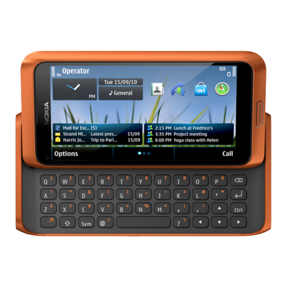
1–10 Table 3 Data ................................ 1–11 Table 4 Messaging .............................. 1–11 Table 5 Power ..............................1–11 List of Figures Figure 1 View of RM-626............................1–5 Issue 1 COMPANY CONFIDENTIAL Page 1 – 3 Copyright © 2011 Nokia. All rights reserved. - Page 16 RM-626 General Information (This page left intentionally blank.) Page 1 – 4 COMPANY CONFIDENTIAL Issue 1 Copyright © 2011 Nokia. All rights reserved.
-
Page 17: Product Selection
(in limited use cases). In PS/CS mode, RM-626 supports DTM with multi slot class 32 (max. 5 RX + 3 TX, sum 6). With EGPRS this means maximum download speed of up to 236.8 kbit/s simultaneously with speech. With GPRS this means maximum download speed of up to 85.6 kbit/s simultaneously with speech. -
Page 18: Product Features And Sales Package
• Scene: automatic, portrait, landscape, night, night portrait, user defined • Colour tone: normal, sepia, B&W, vivid, negative • Zoom (digital): 2x Edit • On device Photo editor and Video editor (manual & automatic) Page 1 – 6 COMPANY CONFIDENTIAL Issue 1 Copyright © 2011 Nokia. All rights reserved. - Page 19 • Nokia XpressPrint – direct printing via USB (PictBridge), Bluetooth (BPP), and WLAN (UPnP), from memory card or via online printing Store • 16 GB internal user memory • Nokia XpressTransfer – easy to transfer and organize photos and video between your device and a compatible PC • Nokia Lifeblog (mobile & PC) Music •...
- Page 20 • Nokia Push to Talk (PoC) Connectivity • Integrated GPS (A-GPS OMA SUPL) • Nokia Maps 3.0, including Friend Finder • WLAN - IEEE802.11 g/b/n with UPnP support • HDMI type C connector • Micro USB interface with USB 2.0 high speed •...
-
Page 21: Product And Module List
Type Music headset WH-205 (inbox) Nokia Wireless Stereo Gateway AD-42W Mini speakers MD-8 MD-9 Hearing aids HDA-12 LPS-5 Wired headsets WH-502 WH-700 WH-701 WH-800 WH-900 Issue 1 COMPANY CONFIDENTIAL Page 1 – 9 Copyright © 2011 Nokia. All rights reserved. -
Page 22: Table 2 Car
Type Nokia Universal Mobile Holder CR-122 Speakerphone HF-310 HF-510 Car kit CK-100 Multimedia car kit CK-300 Display car kit CK-600 Mobile charger DC-6 DC-10 DC-11 Page 1 – 10 COMPANY CONFIDENTIAL Issue 1 Copyright © 2011 Nokia. All rights reserved. -
Page 23: Technical Specifications
Main RF characteristics for GSM850/900/1800/1900 and WCDMA VIII/V/IV/II/I phones Parameter Unit Cellular system GSM850, EGSM900, GSM1800/1900, WCDMA VIII (900), WCDMA V (850), WCDMA IV (1700/2100), WCDMA II (1900) and WCDMA I (2100) Issue 1 COMPANY CONFIDENTIAL Page 1 – 11 Copyright © 2011 Nokia. All rights reserved. - Page 24 EDGE900: +5 … +27 dBm/3.2 mW … 501 mW EDGE1800: +0 … +26 dBm/1.0 mW … 398 mW EDGE1900: +0 … +26d dBm/1.0 mW … 398 mW Page 1 – 12 COMPANY CONFIDENTIAL Issue 1 Copyright © 2011 Nokia. All rights reserved.
-
Page 25: Battery Endurance
Up to 470 h (WCDMA) Environmental conditions Temperature conditions Environmental condition Ambient temperature Notes Normal operation Specifications fulfilled C...+55 Reduced performance Operational for shorts periods C...-15 only C...+70 Issue 1 COMPANY CONFIDENTIAL Page 1 – 13 Copyright © 2011 Nokia. All rights reserved. - Page 26 The standard for electrostatic discharge is IEC 61000-4-2, and this device fulfils level 4 requirements. RoHS This device uses RoHS compliant components and lead-free soldering process. Page 1 – 14 COMPANY CONFIDENTIAL Issue 1 Copyright © 2011 Nokia. All rights reserved.
-
Page 27: Issue 1 Company Confidential Page
Nokia Customer Care 2 — Service Tools and Service Concepts Issue 1 COMPANY CONFIDENTIAL Page 2 – 1 Copyright © 2011 Nokia. All rights reserved. - Page 28 RM-626 Service Tools and Service Concepts (This page left intentionally blank.) Page 2 – 2 COMPANY CONFIDENTIAL Issue 1 Copyright © 2011 Nokia. All rights reserved.
-
Page 29: Table Of Contents
Figure 3 Flashing, certificate restore and product code change ..............2–14 Figure 4 Module jig service concept ......................... 2–15 Figure 5 RF testing and BB/RF tuning concept with module jig..............2–16 Issue 1 COMPANY CONFIDENTIAL Page 2 – 3 Copyright © 2011 Nokia. All rights reserved. - Page 30 RM-626 Service Tools and Service Concepts (This page left intentionally blank.) Page 2 – 4 COMPANY CONFIDENTIAL Issue 1 Copyright © 2011 Nokia. All rights reserved.
-
Page 31: Service Tools
The table below gives a short overview of service devices that can be used for testing, error analysis, and repair of product RM-626. For the correct use of the service devices, and the best effort of workbench setup, please refer to various concepts. -
Page 32: General Tools
The table below gives a short overview of service devices that can be used for testing, error analysis, and repair of product RM-626. For the correct use of the service devices, and the best effort of workbench setup, please refer to various concepts. - Page 33 4 Connect an FBUS cable (if necessary). 5 Start Phoenix service software. Note: Phoenix enables CU-4 regulators via USB when it is started. Reconnecting the power supply requires a Phoenix restart. Issue 1 COMPANY CONFIDENTIAL Page 2 – 7 Copyright © 2011 Nokia. All rights reserved.
-
Page 34: Fps-21
In order to access the SD memory card slots inside FPS-21, the prommer needs to be opened by removing the front panel, rear panel and heatsink from the prommer body. Page 2 – 8 COMPANY CONFIDENTIAL Issue 1 Copyright © 2011 Nokia. All rights reserved. - Page 35 Bluetooth. An ACP-8x charger is needed for BER testing and an AXS-4 cable in case of cordless interface usage testing . Sales package includes: • SB-6 test box • Installation and warranty information Issue 1 COMPANY CONFIDENTIAL Page 2 – 9 Copyright © 2011 Nokia. All rights reserved.
- Page 36 WLAN test requires defined position for the device. SRT-6 Opening tool SRT-6 is used to open phone covers. Note: The SRT-6 is included in the Nokia Standard Toolkit. SS-210 Camera removal tool The camera removal tool SS-210 is used to remove/attach the camera module from/to the socket.
-
Page 37: Cables
The table below gives a short overview of service devices that can be used for testing, error analysis, and repair of product RM-626. For the correct use of the service devices, and the best effort of workbench setup, please refer to various concepts. -
Page 38: Ca-89Ds
Power cable The PCS-1 power cable (DC) is used with a docking station, a module jig or a control unit to supply a controlled voltage. Page 2 – 12 COMPANY CONFIDENTIAL Issue 1 Copyright © 2011 Nokia. All rights reserved. -
Page 39: Service Concepts
POS (Point of Sale) flash concept Figure 2 POS flash concept Type Description Product specific tools BL-4D Battery Other tools FLS-5 POS flash dongle PC with service software Issue 1 COMPANY CONFIDENTIAL Page 2 – 13 Copyright © 2011 Nokia. All rights reserved. -
Page 40: Flashing, Certificate Restore And Product Code Change Option 2
Other devices FPS-21 Flash prommer box AC-35 Power supply PK-1 SW security device SX-4 Smart card PC with service software Cables CA-101 Micro USB cable Page 2 – 14 COMPANY CONFIDENTIAL Issue 1 Copyright © 2011 Nokia. All rights reserved. -
Page 41: Module Jig Service Concept
PK-1 SW security device SX-4 Smart card PC with service software Measurement equipment Cables CA-101 Micro USB cable PCS-1 DC power cable XRS-6 RF cable Issue 1 COMPANY CONFIDENTIAL Page 2 – 15 Copyright © 2011 Nokia. All rights reserved. -
Page 42: Rf Testing And Bb/Rf Tuning Concept With Module Jig
Other tools CU-4 Control unit PK-1 SW security device SX-4 Smart card PC with service software Smart card reader Cables DAU-9S MBUS cable PCS-1 Power cable Page 2 – 16 COMPANY CONFIDENTIAL Issue 1 Copyright © 2011 Nokia. All rights reserved. - Page 43 RM-626 Service Tools and Service Concepts Type Description XRS-6 RF cable USB cable CA-158RS Product specific RF adapter cable Issue 1 COMPANY CONFIDENTIAL Page 2 – 17 Copyright © 2011 Nokia. All rights reserved.
- Page 44 RM-626 Service Tools and Service Concepts (This page left intentionally blank.) Page 2 – 18 COMPANY CONFIDENTIAL Issue 1 Copyright © 2011 Nokia. All rights reserved.
- Page 45 Nokia Customer Care 3 — BB Troubleshooting and Manual Tuning Guide Issue 1 COMPANY CONFIDENTIAL Page 3 – 1 Copyright © 2011 Nokia. All rights reserved.
- Page 46 RM-626 BB Troubleshooting and Manual Tuning Guide (This page left intentionally blank.) Page 3 – 2 COMPANY CONFIDENTIAL Issue 1 Copyright © 2011 Nokia. All rights reserved.
-
Page 47: Table 5 Power
3–49 Audio troubleshooting test instructions..................... 3–49 External earpiece troubleshooting......................3–51 External microphone troubleshooting......................3–52 Internal earpiece troubleshooting ......................3–53 Internal handsfree (IHF) troubleshooting....................3–54 Issue 1 COMPANY CONFIDENTIAL Page 3 – 3 Copyright © 2011 Nokia. All rights reserved. - Page 48 3–63 Figure 17 Component layout, bottom side...................... 3–72 Figure 18 GPS layout and basic test points...................... 3–72 Figure 19 GPS Quick Test window ........................3–73 Page 3 – 4 COMPANY CONFIDENTIAL Issue 1 Copyright © 2011 Nokia. All rights reserved.
- Page 49 RM-626 BB Troubleshooting and Manual Tuning Guide Figure 20 GPS Control dialogue box ......................... 3–74 Issue 1 COMPANY CONFIDENTIAL Page 3 – 5 Copyright © 2011 Nokia. All rights reserved.
- Page 50 RM-626 BB Troubleshooting and Manual Tuning Guide (This page left intentionally blank.) Page 3 – 6 COMPANY CONFIDENTIAL Issue 1 Copyright © 2011 Nokia. All rights reserved.
-
Page 51: Baseband Main Troubleshooting
Always start the troubleshooting procedure by running the Phoenix self tests. If a test fails, please follow the Dead or jammed device diagrams below. If the phone is dead and you cannot perform the self tests, go to troubleshooting . Issue 1 COMPANY CONFIDENTIAL Page 3 – 7 Copyright © 2011 Nokia. All rights reserved. - Page 52 RM-626 BB Troubleshooting and Manual Tuning Guide Troubleshooting flow - Page 1 of 3 Page 3 – 8 COMPANY CONFIDENTIAL Issue 1 Copyright © 2011 Nokia. All rights reserved.
- Page 53 RM-626 BB Troubleshooting and Manual Tuning Guide Troubleshooting flow - Page 2 of 3 Issue 1 COMPANY CONFIDENTIAL Page 3 – 9 Copyright © 2011 Nokia. All rights reserved.
- Page 54 RM-626 BB Troubleshooting and Manual Tuning Guide Troubleshooting flow - Page 3 of 3 Page 3 – 10 COMPANY CONFIDENTIAL Issue 1 Copyright © 2011 Nokia. All rights reserved.
-
Page 55: Power And Charging Troubleshooting
RM-626 BB Troubleshooting and Manual Tuning Guide Power and charging troubleshooting Battery current measuring fault troubleshooting Troubleshooting flow Issue 1 COMPANY CONFIDENTIAL Page 3 – 11 Copyright © 2011 Nokia. All rights reserved. -
Page 56: General Power Checking Troubleshooting
RM-626 BB Troubleshooting and Manual Tuning Guide General power checking troubleshooting Troubleshooting flow Page 3 – 12 COMPANY CONFIDENTIAL Issue 1 Copyright © 2011 Nokia. All rights reserved. -
Page 57: Dead Or Jammed Device Troubleshooting
RM-626 BB Troubleshooting and Manual Tuning Guide Dead or jammed device troubleshooting Troubleshooting flow Issue 1 COMPANY CONFIDENTIAL Page 3 – 13 Copyright © 2011 Nokia. All rights reserved. -
Page 58: Clocking Troubleshooting
RM-626 BB Troubleshooting and Manual Tuning Guide Clocking troubleshooting Troubleshooting flow Page 3 – 14 COMPANY CONFIDENTIAL Issue 1 Copyright © 2011 Nokia. All rights reserved. -
Page 59: Usb Charging Troubleshooting
RM-626 BB Troubleshooting and Manual Tuning Guide USB charging troubleshooting Troubleshooting flow Issue 1 COMPANY CONFIDENTIAL Page 3 – 15 Copyright © 2011 Nokia. All rights reserved. -
Page 60: Interface Troubleshooting
RM-626 BB Troubleshooting and Manual Tuning Guide Interface troubleshooting USB flashing fault troubleshooting Troubleshooting flow Page 3 – 16 COMPANY CONFIDENTIAL Issue 1 Copyright © 2011 Nokia. All rights reserved. -
Page 61: Usb Data Interface Troubleshooting
RM-626 BB Troubleshooting and Manual Tuning Guide USB data interface troubleshooting Troubleshooting flow Issue 1 COMPANY CONFIDENTIAL Page 3 – 17 Copyright © 2011 Nokia. All rights reserved. -
Page 62: Sim Card Troubleshooting
RM-626 BB Troubleshooting and Manual Tuning Guide SIM card troubleshooting Troubleshooting flow Page 3 – 18 COMPANY CONFIDENTIAL Issue 1 Copyright © 2011 Nokia. All rights reserved. - Page 63 RM-626 BB Troubleshooting and Manual Tuning Guide Figure 6 SIM power-on sequence on X2700 Figure 7 SIM connector X2700 contacts Issue 1 COMPANY CONFIDENTIAL Page 3 – 19 Copyright © 2011 Nokia. All rights reserved.
-
Page 64: Memory Troubleshooting
RM-626 BB Troubleshooting and Manual Tuning Guide Memory troubleshooting External memory eMMC troubleshooting Troubleshooting flow Page 3 – 20 COMPANY CONFIDENTIAL Issue 1 Copyright © 2011 Nokia. All rights reserved. -
Page 65: Nor Troubleshooting
NOR flash interface is an electrical interface between the memory and the digital ASIC. It is used for accessing the memory IC for SW instructions and data. Troubleshooting flow Issue 1 COMPANY CONFIDENTIAL Page 3 – 21 Copyright © 2011 Nokia. All rights reserved. -
Page 66: Sdram Troubleshooting
SDRAM interface is an electrical interface between the memory and the digital Asic. It is used for accessing the memory IC for SW instructions and data. Troubleshooting flow Page 3 – 22 COMPANY CONFIDENTIAL Issue 1 Copyright © 2011 Nokia. All rights reserved. -
Page 67: Ive Troubleshooting
L1403/C1466 VBAT supply to BCM2727B J1425 Enable signal to IVE. This needs to be High for IVE to be Up. C1448 19.2MHz clock to IVE Issue 1 COMPANY CONFIDENTIAL Page 3 – 23 Copyright © 2011 Nokia. All rights reserved. -
Page 68: Ive Troubleshooting
RM-626 BB Troubleshooting and Manual Tuning Guide IVE troubleshooting Troubleshooting flow Page 3 – 24 COMPANY CONFIDENTIAL Issue 1 Copyright © 2011 Nokia. All rights reserved. -
Page 69: Tv Out Troubleshooting
Z1650 to Z1653 Common mode choke on HDMI bus N1651 HDMI 5V regulator D1400 BCM2727B IC D1653 HPD signal buffer V1657 HDMI +5V ESD protection Issue 1 COMPANY CONFIDENTIAL Page 3 – 25 Copyright © 2011 Nokia. All rights reserved. - Page 70 The following test points on the PWB help in the effective debugging and troubleshooting. Sr No Signal name Measuring point Description CVBS X2001.1/J2002 SDTV signal Page 3 – 26 COMPANY CONFIDENTIAL Issue 1 Copyright © 2011 Nokia. All rights reserved.
-
Page 71: Hdtv Out Troubleshooting
RM-626 BB Troubleshooting and Manual Tuning Guide HDTV out troubleshooting Troubleshooting flow Issue 1 COMPANY CONFIDENTIAL Page 3 – 27 Copyright © 2011 Nokia. All rights reserved. -
Page 72: Sdtv Out Troubleshooting
RM-626 BB Troubleshooting and Manual Tuning Guide SDTV out troubleshooting Troubleshooting flow Page 3 – 28 COMPANY CONFIDENTIAL Issue 1 Copyright © 2011 Nokia. All rights reserved. - Page 73 RM-626 BB Troubleshooting and Manual Tuning Guide Figure 9 Expected SDTV CVBS PAL signal on Oscilloscope Issue 1 COMPANY CONFIDENTIAL Page 3 – 29 Copyright © 2011 Nokia. All rights reserved.
-
Page 74: Display Module Troubleshooting
If a part of the image is missing, change the display module. If the image is otherwise corrupted, follow the appropriate troubleshooting diagram. Page 3 – 30 COMPANY CONFIDENTIAL Issue 1 Copyright © 2011 Nokia. All rights reserved. -
Page 75: Introduction To Display Troubleshooting
FPC with a 20 pins board to board connector. The following references on the PWB help in the effective debugging and troubleshooting of the display. Issue 1 COMPANY CONFIDENTIAL Page 3 – 31 Copyright © 2011 Nokia. All rights reserved. - Page 76 Sr. No Signal name Measuring point Description L8002/C8005 1.8V supply to display VBAT L8003/C8007 VBAT supply to display J1429 Tearing effect signal from display module. Page 3 – 32 COMPANY CONFIDENTIAL Issue 1 Copyright © 2011 Nokia. All rights reserved.
-
Page 77: Display Fault Troubleshooting
RM-626 BB Troubleshooting and Manual Tuning Guide Display fault troubleshooting Troubleshooting flow Issue 1 COMPANY CONFIDENTIAL Page 3 – 33 Copyright © 2011 Nokia. All rights reserved. -
Page 78: Touch Panel Troubleshooting
RM-626 BB Troubleshooting and Manual Tuning Guide Touch panel troubleshooting Troubleshooting flow Page 3 – 34 COMPANY CONFIDENTIAL Issue 1 Copyright © 2011 Nokia. All rights reserved. -
Page 79: Illumination Troubleshooting
RM-626 BB Troubleshooting and Manual Tuning Guide Illumination troubleshooting Charging illumination troubleshooting Troubleshooting flow Issue 1 COMPANY CONFIDENTIAL Page 3 – 35 Copyright © 2011 Nokia. All rights reserved. -
Page 80: Menu Key Lights Troubleshooting
RM-626 BB Troubleshooting and Manual Tuning Guide Menu key lights troubleshooting Troubleshooting flow Page 3 – 36 COMPANY CONFIDENTIAL Issue 1 Copyright © 2011 Nokia. All rights reserved. -
Page 81: Qwerty Keys Backlight Troubleshooting
RM-626 BB Troubleshooting and Manual Tuning Guide Qwerty keys backlight troubleshooting Troubleshooting flow Issue 1 COMPANY CONFIDENTIAL Page 3 – 37 Copyright © 2011 Nokia. All rights reserved. -
Page 82: Keyboard Troubleshooting
RM-626 BB Troubleshooting and Manual Tuning Guide Keyboard troubleshooting Keys troubleshooting Troubleshooting flow Page 3 – 38 COMPANY CONFIDENTIAL Issue 1 Copyright © 2011 Nokia. All rights reserved. -
Page 83: Qwerty Keyboard Troubleshooting
RM-626 BB Troubleshooting and Manual Tuning Guide Qwerty keyboard troubleshooting Troubleshooting flow Issue 1 COMPANY CONFIDENTIAL Page 3 – 39 Copyright © 2011 Nokia. All rights reserved. -
Page 84: Power Key Troubleshooting
RM-626 BB Troubleshooting and Manual Tuning Guide Power key troubleshooting Troubleshooting flow Page 3 – 40 COMPANY CONFIDENTIAL Issue 1 Copyright © 2011 Nokia. All rights reserved. -
Page 85: Sensors Troubleshooting
RM-626 BB Troubleshooting and Manual Tuning Guide Sensors troubleshooting Slide sensor troubleshooting Troubleshooting flow Issue 1 COMPANY CONFIDENTIAL Page 3 – 41 Copyright © 2011 Nokia. All rights reserved. -
Page 86: Accelerometer Troubleshooting
RM-626 BB Troubleshooting and Manual Tuning Guide Accelerometer troubleshooting Troubleshooting flow Page 3 – 42 COMPANY CONFIDENTIAL Issue 1 Copyright © 2011 Nokia. All rights reserved. -
Page 87: Magnetometer Troubleshooting
• Set the phone and reference compass to the rotating platform • Connect the phone to the PC and start Phoenix Tests • General troubleshooting test • Self-test (ST) • Azimuth check test Issue 1 COMPANY CONFIDENTIAL Page 3 – 43 Copyright © 2011 Nokia. All rights reserved. - Page 88 • No disturbing elements near the table, such as motors, coils, electric currents or similar • Calibrate the phone as described in the user manual • The indicator must be GREEN Page 3 – 44 COMPANY CONFIDENTIAL Issue 1 Copyright © 2011 Nokia. All rights reserved.
- Page 89 • The result is the real angle difference of angles in a 360° degrees continuous round • Criteria: • If the Result(angle) value < 15° degrees GO, otherwise NOGO Issue 1 COMPANY CONFIDENTIAL Page 3 – 45 Copyright © 2011 Nokia. All rights reserved.
-
Page 90: Proximity Sensor Troubleshooting
RM-626 BB Troubleshooting and Manual Tuning Guide Proximity sensor troubleshooting Troubleshooting flow Page 3 – 46 COMPANY CONFIDENTIAL Issue 1 Copyright © 2011 Nokia. All rights reserved. -
Page 91: Als Technical Description And Troubleshooting
1. Place the phone to the calibration jig. 2. Make sure that the Kodak90% reflector is 50 mm above the proximity sensor. 3. Set the phone to Local mode with Phoenix. Issue 1 COMPANY CONFIDENTIAL Page 3 – 47 Copyright © 2011 Nokia. All rights reserved. - Page 92 8. If the Irradiance value is <100, the result is FAIL. Lower the reflector (min. 30 mm) and repeat Step 6. until the value is 100-105. 9. The proximity sensor is tuned. Page 3 – 48 COMPANY CONFIDENTIAL Issue 1 Copyright © 2011 Nokia. All rights reserved.
-
Page 93: Als Troubleshooting
Single-ended external earpiece and differential internal earpiece outputs can be measured either with a single-ended or a differential probe. When measuring with a single-ended probe each output is measured against the ground. Issue 1 COMPANY CONFIDENTIAL Page 3 – 49 Copyright © 2011 Nokia. All rights reserved. - Page 94 L2158 & headset mic L2159 to IHF mono Internal Acoustical HS_L & GND 94 dBSPL digital Input, 1kHz HS_R & GND microphone sine wave to headset Page 3 – 50 COMPANY CONFIDENTIAL Issue 1 Copyright © 2011 Nokia. All rights reserved.
-
Page 95: External Earpiece Troubleshooting
RM-626 BB Troubleshooting and Manual Tuning Guide External earpiece troubleshooting Troubleshooting flow Issue 1 COMPANY CONFIDENTIAL Page 3 – 51 Copyright © 2011 Nokia. All rights reserved. -
Page 96: External Microphone Troubleshooting
RM-626 BB Troubleshooting and Manual Tuning Guide External microphone troubleshooting Troubleshooting flow Page 3 – 52 COMPANY CONFIDENTIAL Issue 1 Copyright © 2011 Nokia. All rights reserved. -
Page 97: Internal Earpiece Troubleshooting
RM-626 BB Troubleshooting and Manual Tuning Guide Internal earpiece troubleshooting Troubleshooting flow Issue 1 COMPANY CONFIDENTIAL Page 3 – 53 Copyright © 2011 Nokia. All rights reserved. -
Page 98: Internal Handsfree (Ihf) Troubleshooting
RM-626 BB Troubleshooting and Manual Tuning Guide Internal handsfree (IHF) troubleshooting Troubleshooting flow Page 3 – 54 COMPANY CONFIDENTIAL Issue 1 Copyright © 2011 Nokia. All rights reserved. -
Page 99: Internal Microphone Troubleshooting
RM-626 BB Troubleshooting and Manual Tuning Guide Internal microphone troubleshooting Troubleshooting flow Issue 1 COMPANY CONFIDENTIAL Page 3 – 55 Copyright © 2011 Nokia. All rights reserved. -
Page 100: Vibra Troubleshooting
SMPS supplies the whole BOB1.0M-b solution from the phone battery supply, VBAT, apart from VIO which is needed for interface signal reference levels. The following figure shows a top level block diagram of the BOB1.0M-b module. Page 3 – 56 COMPANY CONFIDENTIAL Issue 1 Copyright © 2011 Nokia. All rights reserved. - Page 101 The FM radio audio signal is routed to the headset connector through the BB ASIC shared by the phone audio functions. The antenna positions are presented in the following figure. Figure 13 WLAN/Bluetooth and GPS antennas Issue 1 COMPANY CONFIDENTIAL Page 3 – 57 Copyright © 2011 Nokia. All rights reserved.
-
Page 102: Bluetooth/Fm Radio And Wlan Troubleshooting
Open circuit solder joints or Replacement of BOB module Bluetooth device, but unable to component failure of BOB hear audio through functional module (PCM interface) Bluetooth headset Page 3 – 58 COMPANY CONFIDENTIAL Issue 1 Copyright © 2011 Nokia. All rights reserved. - Page 103 Replacement of BOB module ST_BT_WAKEUP_TEST interface (or repair of phone BB) Bluetooth Self Test: Bluetooth ASIC PCM interface Replacement of BOB module ST_LPRF_AUDIO_LINES_TEST (or repair of phone BB) Issue 1 COMPANY CONFIDENTIAL Page 3 – 59 Copyright © 2011 Nokia. All rights reserved.
-
Page 104: Introduction To Wlan Troubleshooting
Repair solution WLAN does not operate as desired Other WLAN device is not Use only certified WLAN with another WLAN device conforming to ETSI/FCC products specifications Page 3 – 60 COMPANY CONFIDENTIAL Issue 1 Copyright © 2011 Nokia. All rights reserved. -
Page 105: Bluetooth And Fm Radio Self Tests In Phoenix
5. Choose Testing → Self Tests. Self Tests window check the following Bluetooth and FM radio related tests: 6. In the • ST_LPRF_IF_TEST • ST_LPRF_AUDIO_LINES_TEST • ST_BT_WAKEUP_TEST Issue 1 COMPANY CONFIDENTIAL Page 3 – 61 Copyright © 2011 Nokia. All rights reserved. -
Page 106: Wlan Self Test In Phoenix
Bluetooth functionality can be checked by transferring a file to another Bluetooth phone. Steps 1. Connect data cable to phone. Phoenix service software. 2. Start Page 3 – 62 COMPANY CONFIDENTIAL Issue 1 Copyright © 2011 Nokia. All rights reserved. -
Page 107: Fmrx Radio Receiver Testing
• Frequency 100MHz • FM deviation 22kHz • Modulation frequency 1kHz • RF level should be varied during the test to obtain good audio signal quality Issue 1 COMPANY CONFIDENTIAL Page 3 – 63 Copyright © 2011 Nokia. All rights reserved. -
Page 108: Wlan Tx And Rx Testing In Phoenix
Note: You may alternately use a known good FM radio broadcast as a test signal. 2. Attach the Nokia headset to the phone’s AV connector. 3. Use Scroll button to autotune to the radio frequency. 4. Set volume to suitable level. - Page 109 Click Start Power Calibration and read the result from the Result box. 10. If TXPowerCal response returns ‘Passed’ results, the WLAN TX BiP test is successful. Issue 1 COMPANY CONFIDENTIAL Page 3 – 65 Copyright © 2011 Nokia. All rights reserved.
-
Page 110: Wlan Tx Bip Testing Procedure In Testing And Tuning Tool
1. Make sure the phone is connected to the PC. Nokia Care Suite application. 2. Start 3. To open the application, double-click the Testing And Tuning Tool icon. Page 3 – 66 COMPANY CONFIDENTIAL Issue 1 Copyright © 2011 Nokia. All rights reserved. - Page 111 4. If the application is able to find a connected phone, the following view will open: 5. Click on the RF Tuning button and select from the drop-down menu: Issue 1 COMPANY CONFIDENTIAL Page 3 – 67 Copyright © 2011 Nokia. All rights reserved.
- Page 112 7. If errors do happen, failed tuning/testing steps are marked with a red color and more detailed results are shown on the screen. Page 3 – 68 COMPANY CONFIDENTIAL Issue 1 Copyright © 2011 Nokia. All rights reserved.
-
Page 113: Bluetooth Troubleshooting
RM-626 BB Troubleshooting and Manual Tuning Guide Bluetooth troubleshooting Troubleshooting flow Issue 1 COMPANY CONFIDENTIAL Page 3 – 69 Copyright © 2011 Nokia. All rights reserved. -
Page 114: Fmrx Receiver Troubleshooting
RM-626 BB Troubleshooting and Manual Tuning Guide FMRX receiver troubleshooting Troubleshooting flow Page 3 – 70 COMPANY CONFIDENTIAL Issue 1 Copyright © 2011 Nokia. All rights reserved. -
Page 115: Wlan Troubleshooting
The GPS components are located on the bottom side of the PWB. Satellite signals are picked up by the GPS antenna in the top end cap. The signal is then processed by the GPS5350 receiver ASIC. Issue 1 COMPANY CONFIDENTIAL Page 3 – 71 Copyright © 2011 Nokia. All rights reserved. - Page 116 RM-626 BB Troubleshooting and Manual Tuning Guide Figure 17 Component layout, bottom side Figure 18 GPS layout and basic test points Page 3 – 72 COMPANY CONFIDENTIAL Issue 1 Copyright © 2011 Nokia. All rights reserved.
-
Page 117: Gps Settings For Phoenix
1. Place phone to Flash Adaptor. 2. Start Phoenix service software. 3. From the File menu, select Scan Product and check that the correct product version is displayed. Issue 1 COMPANY CONFIDENTIAL Page 3 – 73 Copyright © 2011 Nokia. All rights reserved. -
Page 118: Gps Failure Troubleshooting
GPS troubleshooting is broken down into two parts: general GPS failure troubleshooting and GPS basic checks troubleshooting. The GPS failure troubleshooting flow can be followed and, where applicable, will feed into the GPS basic checks troubleshooting flow. Page 3 – 74 COMPANY CONFIDENTIAL Issue 1 Copyright © 2011 Nokia. All rights reserved. - Page 119 RM-626 BB Troubleshooting and Manual Tuning Guide Troubleshooting flow Issue 1 COMPANY CONFIDENTIAL Page 3 – 75 Copyright © 2011 Nokia. All rights reserved.
-
Page 120: Gps Basic Checks Troubleshooting
RM-626 BB Troubleshooting and Manual Tuning Guide GPS basic checks troubleshooting Troubleshooting flow Page 3 – 76 COMPANY CONFIDENTIAL Issue 1 Copyright © 2011 Nokia. All rights reserved. -
Page 121: Baseband Manual Tuning Guide
• When certificate restoring for BB 5 products or IMEI rebuild for DCT-4 products is performed, existing data from Nokia System is programmed in the phone. The phone will be in the same condition as it was when it left the factory for the first time. - Page 122 5. Product code shown on the UI does not matter, because during restoring it will be replaced by the product code which is the latest one stored in Nokia system. 6. It is recommended to perform "Restore"-function without selecting "Flash Product"-option to avoid possible SW downgrade which causes the phone to die.
- Page 123 RM-626 BB Troubleshooting and Manual Tuning Guide 7. Information from phone and Smart Card are read and connection to Tucson server is established. 8. Information from Nokia system is retreived and programmed in the phone. Issue 1 COMPANY CONFIDENTIAL Page 3 – 79...
-
Page 124: Product Code Change
Nokia System, and programmed in the phone. • After successful change, phone specific information in Nokia systems will match the new variant, and it can be used for e.g. certificate restoring. If you perform several product code changes, Nokia system will always be up to date with the latest successful event. - Page 125 Select product code of new variant from list. If the product code you want is not shown, please install correct data package including the variant. Select “OK” and “SWAP”. Issue 1 COMPANY CONFIDENTIAL Page 3 – 81 Copyright © 2011 Nokia. All rights reserved.
- Page 126 BB Troubleshooting and Manual Tuning Guide Information from phone is read and connection to Tucson server is established. If “Flash Product” – option was selected, phone SW is programmed. Page 3 – 82 COMPANY CONFIDENTIAL Issue 1 Copyright © 2011 Nokia. All rights reserved.
- Page 127 RM-626 BB Troubleshooting and Manual Tuning Guide New data retrieved from Nokia system is programmed in the phone. Confirmation about successful event is sent to Nokia system. Issue 1 COMPANY CONFIDENTIAL Page 3 – 83 Copyright © 2011 Nokia. All rights reserved.
-
Page 128: Energy Management Calibration
Energy Management (EM) calibration is performed to calibrate the setting (gain and offset) of AD converters in several channels (that is, battery voltage, BSI, battery current) to get an accurate AD conversion result. Hardware setup: Page 3 – 84 COMPANY CONFIDENTIAL Issue 1 Copyright © 2011 Nokia. All rights reserved. - Page 129 Write and/or repeat the procedure again. Energy Management Calibration window. 10. To end the procedure, close the Issue 1 COMPANY CONFIDENTIAL Page 3 – 85 Copyright © 2011 Nokia. All rights reserved.
- Page 130 RM-626 BB Troubleshooting and Manual Tuning Guide (This page left intentionally blank.) Page 3 – 86 COMPANY CONFIDENTIAL Issue 1 Copyright © 2011 Nokia. All rights reserved.
- Page 131 Nokia Customer Care 4 — Cellular RF troubleshooting Issue 1 COMPANY CONFIDENTIAL Page 4 – 1 Copyright © 2011 Nokia. All rights reserved.
- Page 132 RM-626 Cellular RF troubleshooting (This page left intentionally blank.) Page 4 – 2 COMPANY CONFIDENTIAL Issue 1 Copyright © 2011 Nokia. All rights reserved.
-
Page 133: Table
4–14 VDCDCA (Vlow) level ..........................4–15 level..............................4–15 RF tuning and testing ............................4–16 RF auto tuning and testing with Nokia Care Suite..................4–16 RF auto tuning procedure ..........................4–17 Automatic RF testing with Nokia Care Suite....................4–21 Troubleshooting with Testing And Tuning Tool .................. - Page 134 RM-626 Cellular RF troubleshooting (This page left intentionally blank.) Page 4 – 4 COMPANY CONFIDENTIAL Issue 1 Copyright © 2011 Nokia. All rights reserved.
-
Page 135: General Instructions For Cellular Rf Troubleshooting
RF components have been changed or memory (D3000) is corrupted. RF shield cans Once a peel-off type RF shield can is opened, a repair lid (Nokia code 9501325) should always be installed. RF shielding does not work at all if RF shield cans are left open. -
Page 136: Cellular Rf Key Components
• Älli N7512 + surroundings (Shield C) • QuBBE Z7513 + Ukko PA N7510 (Shield B) • Aura N7509 + surroundings (Shield A) Figure 21 Linko shields Page 4 – 6 COMPANY CONFIDENTIAL Issue 1 Copyright © 2011 Nokia. All rights reserved. -
Page 137: Cellular Rf Main Troubleshooting
The maximum height of the shields is 1.70 mm. Cellular RF main troubleshooting Cellular RF main troubleshooting Context Always start the cellular RF related troubleshooting procedure by following the diagram below. Issue 1 COMPANY CONFIDENTIAL Page 4 – 7 Copyright © 2011 Nokia. All rights reserved. - Page 138 RM-626 Cellular RF troubleshooting Troubleshooting flow — Page 1 of 2 Page 4 – 8 COMPANY CONFIDENTIAL Issue 1 Copyright © 2011 Nokia. All rights reserved.
- Page 139 RM-626 Cellular RF troubleshooting Troubleshooting flow — Page 2 of 2 Issue 1 COMPANY CONFIDENTIAL Page 4 – 9 Copyright © 2011 Nokia. All rights reserved.
-
Page 140: Self Test Troubleshooting
• Tests the basic functionality of the WCDMA transmitter. To get the best out of these instructions you need to have the valid schematics at hand. Page 4 – 10 COMPANY CONFIDENTIAL Issue 1 Copyright © 2011 Nokia. All rights reserved. - Page 141 RM-626 Cellular RF troubleshooting Troubleshooting flow Issue 1 COMPANY CONFIDENTIAL Page 4 – 11 Copyright © 2011 Nokia. All rights reserved.
-
Page 142: Rf Supply Self Test Troubleshooting
RM-626 Cellular RF troubleshooting RF supply self test troubleshooting Troubleshooting flow Page 4 – 12 COMPANY CONFIDENTIAL Issue 1 Copyright © 2011 Nokia. All rights reserved. -
Page 143: Vbat Level
Check the VBAT level at the L7504. The level should be the same as the battery voltage and always on. VIO level Check the VIO level (1.8V) at C2806. The signal is always on when the phone is in local mode. Issue 1 COMPANY CONFIDENTIAL Page 4 – 13 Copyright © 2011 Nokia. All rights reserved. -
Page 144: Vref Level
Follow the instructions given in chapter 'Manual transmitter (TX) testing with Phoenix → GSM transmitter activation' or 'WCDMA transmitter activation'. VHIA (Vhi) level Check the VHIA level (2.6 V) at L7509. Page 4 – 14 COMPANY CONFIDENTIAL Issue 1 Copyright © 2011 Nokia. All rights reserved. -
Page 145: Vdcdca (Vlow) Level
'Manual transmitter (TX) testing with Phoenix → GSM transmitter activation' or 'WCDMA transmitter activation'. Check the VPA voltage level at C7514. Issue 1 COMPANY CONFIDENTIAL Page 4 – 15 Copyright © 2011 Nokia. All rights reserved. -
Page 146: Rf Tuning And Testing
RF components are changed or memory (D3000) is corrupted. RM-626 can be tuned automatically. Auto tuning is designed to align the phone's RF part easily and faster. It performs calibrations, tunings and measurements of RX and TX. The results are displayed and logged in a result file, if initiated. -
Page 147: Rf Auto Tuning Procedure
Nokia Care Suite preparations Install Testing And Tuning Tool add-on application to Nokia Care Suite. Automatic RF testing and tuning is not possible without this application. There is no more support in Phoenix to auto tune RM-626 product. Nokia_firmware_RM-626_EUROPE_10.014_v41.0.exe . This Install the phone specific data package, for example defines phone specific settings. - Page 148 To open the application, double-click Testing And Tuning Tool icon. If the application is able to find a connected phone, the following view will open: Page 4 – 18 COMPANY CONFIDENTIAL Issue 1 Copyright © 2011 Nokia. All rights reserved.
- Page 149 Select Cellular RF Tunings and Tests from the drop-down menu. Select the RF cable used (and possible RF splitter / RF shield box) from the drop-down menu. CA-158RS attenuation values are always taken automatically into account when RM-626 product is connected to Nokia Care Suite tool.
- Page 150 RM-626 Cellular RF troubleshooting Nokia Care Suite and Testing And Tuning Note: The window appearance may differ depending on the Tool versions 10 If no critical errors happen during the low band RF tuning procedure, the following window will pop up: 11 Change the CA-158RS cable to the high band RF connector on the phone PWB.
-
Page 151: Automatic Rf Testing With Nokia Care Suite
RM-626 Cellular RF troubleshooting Nokia Care Suite and Testing And Tuning Note: The window appearance may differ depending on the Tool versions Automatic RF testing with Nokia Care Suite Testing And Tuning Tool add-on application can be used also for non-signalling RF tests. The automatic RF... -
Page 152: Troubleshooting With Testing And Tuning Tool
RM-626 Cellular RF troubleshooting Nokia Care Suite and Testing And Tuning Note: The window appearance may differ depending on the Tool versions. RF Testing selection does all the same measurements as RF Tuning , but does not perform any tunings. - Page 153 Note: Start the more specific troubleshooting always from the chapter troubleshooting . The troubleshooting flow below may be misleading if followed without upper level instructions. Issue 1 COMPANY CONFIDENTIAL Page 4 – 23 Copyright © 2011 Nokia. All rights reserved.
- Page 154 RM-626 Cellular RF troubleshooting Troubleshooting flow — Page 1 of 3 Page 4 – 24 COMPANY CONFIDENTIAL Issue 1 Copyright © 2011 Nokia. All rights reserved.
- Page 155 RM-626 Cellular RF troubleshooting Troubleshooting flow — Page 2 of 3 Issue 1 COMPANY CONFIDENTIAL Page 4 – 25 Copyright © 2011 Nokia. All rights reserved.
-
Page 156: Manual Transmitter (Tx) Testing With Phoenix
1. Set the phone to local mode. 2. Activate the RF controls tool in Phoenix ( Testing → GSM → RF Controls ). 3. Make settings as shown in the figure: Page 4 – 26 COMPANY CONFIDENTIAL Issue 1 Copyright © 2011 Nokia. All rights reserved. - Page 157 (for example CMU–200). Change power level (in “RF Controls” tool) and make sure the power reading follows accordingly. Issue 1 COMPANY CONFIDENTIAL Page 4 – 27 Copyright © 2011 Nokia. All rights reserved.
- Page 158 RM-626 Cellular RF troubleshooting Page 4 – 28 COMPANY CONFIDENTIAL Issue 1 Copyright © 2011 Nokia. All rights reserved.
-
Page 159: Wcdma Transmitter Activation
Optional step (not needed if WCDMA TX activation only required): Check the basic TX parameters using a communication analyzer (for example CMU–200). Issue 1 COMPANY CONFIDENTIAL Page 4 – 29 Copyright © 2011 Nokia. All rights reserved. -
Page 160: Manual Receiver (Rx) Testing With Phoenix
For GSM RSSI measurements, see chapter measurements/GSM RSSI measurement . For a similar test in WCDMA mode, see chapter WCDMA RSSI measurement . Page 4 – 30 COMPANY CONFIDENTIAL Issue 1 Copyright © 2011 Nokia. All rights reserved. -
Page 161: Gsm Rx Chain Activation For Manual Measurements/Gsm Rssi Measurement
1. Set the phone to local mode. RX Control tool in Phoenix (Testing —> WCDMA —> RX Control) . 2. Activate 3. In the RX Control window, make the following settings: Issue 1 COMPANY CONFIDENTIAL Page 4 – 31 Copyright © 2011 Nokia. All rights reserved. -
Page 162: Wcdma Rssi Measurement
RX frequency 2140.0 MHz 1960.0 MHz 2132.4 MHz 881.6 MHz 942.4 MHz Signal generator 2141.0 MHz 1961.0 MHz 2133.4 MHz 882.6 MHz 943.4 MHz frequency Page 4 – 32 COMPANY CONFIDENTIAL Issue 1 Copyright © 2011 Nokia. All rights reserved. -
Page 163: Antenna
PWB and the antenna flex assembly are implemented by C-clip contacts (3 pieces) and two coaxial cables (one for low band and the other for high band). Issue 1 COMPANY CONFIDENTIAL Page 4 – 33 Copyright © 2011 Nokia. All rights reserved. -
Page 164: Antenna Troubleshooting
(both ends) and the cables are undamaged. Check that the C-clips are clearly open and the matching capacitor C7000 (12pF) has been soldered to the PWB. Page 4 – 34 COMPANY CONFIDENTIAL Issue 1 Copyright © 2011 Nokia. All rights reserved. - Page 165 C-clips on the main PWB (see the following figure) and the WLAN/BT antenna flex assembly is visually intact. Check that the C-clips are clearly open. Issue 1 COMPANY CONFIDENTIAL Page 4 – 35 Copyright © 2011 Nokia. All rights reserved.
- Page 166 C-clips on the main PWB (see the following figure) and the GPS antenna flex assembly is visually intact. Check that the C-clips are clearly open. Figure 27 GPS antenna contacts Page 4 – 36 COMPANY CONFIDENTIAL Issue 1 Copyright © 2011 Nokia. All rights reserved.
- Page 167 Nokia Customer Care 5 — Camera Module Troubleshooting Issue 1 COMPANY CONFIDENTIAL Page 5 – 1 Copyright © 2011 Nokia. All rights reserved.
- Page 168 RM-626 Camera Module Troubleshooting (This page left intentionally blank.) Page 5 – 2 COMPANY CONFIDENTIAL Issue 1 Copyright © 2011 Nokia. All rights reserved.
- Page 169 Figure 41 Enlargement of a hot pixel....................... 5–14 Figure 42 Light from the flash has reflected on particles in front of the camera ........5–14 Issue 1 COMPANY CONFIDENTIAL Page 5 – 3 Copyright © 2011 Nokia. All rights reserved.
- Page 170 RM-626 Camera Module Troubleshooting (This page left intentionally blank.) Page 5 – 4 COMPANY CONFIDENTIAL Issue 1 Copyright © 2011 Nokia. All rights reserved.
-
Page 171: Introduction To Camera Module Troubleshooting
Analogous to ISO speed in photographic film. Issue 1 COMPANY CONFIDENTIAL Page 5 – 5 Copyright © 2011 Nokia. All rights reserved. -
Page 172: The Effect Of Image Taking Conditions On Image Quality
The movement of camera or object sometimes cause blurring indoors or in dim lighting conditions because of long exposure time. This is normal; do not change the camera module. Page 5 – 6 COMPANY CONFIDENTIAL Issue 1 Copyright © 2011 Nokia. All rights reserved. - Page 173 In practice, this means that when taking an image indoors and having, for example, a window behind the object, the result is usually poor. This is normal behaviour; do not change the camera module. Issue 1 COMPANY CONFIDENTIAL Page 5 – 7 Copyright © 2011 Nokia. All rights reserved.
- Page 174 Generally this kind of reflections are common in all optical systems. This is normal behaviour; do not change the camera module. Page 5 – 8 COMPANY CONFIDENTIAL Issue 1 Copyright © 2011 Nokia. All rights reserved.
- Page 175 Figure 33 A lens reflection effect caused by sunshine Examples of good quality images Figure 34 Good image taken indoors Figure 35 Good image taken outdoors Issue 1 COMPANY CONFIDENTIAL Page 5 – 9 Copyright © 2011 Nokia. All rights reserved.
-
Page 176: Image Quality Analysis
However, it is possible that a larger particle disturbs the user, causing need for service. Figure 36 Effects of dust on optical path Page 5 – 10 COMPANY CONFIDENTIAL Issue 1 Copyright © 2011 Nokia. All rights reserved. -
Page 177: Testing Camera Image Sharpness
Any particles inside the cavity between the protection window and lens have most probably been trapped there in the assembly phase at a Nokia factory. Unauthorized disassembling of the product can also be the root of the problem. However, in most cases it should be possible to remove the particle(s) by using clean compressed air. - Page 178 A smeared fingerprint may be hard to see on the protective window but if will affect the image quality. These flares can be avoided by cleaning the window with a suitable cloth. Page 5 – 12 COMPANY CONFIDENTIAL Issue 1 Copyright © 2011 Nokia. All rights reserved.
-
Page 179: Faulty Pixels In Images
When examining an image for defect pixels, test images should be viewed as 100% enlargements on a PC monitor. Issue 1 COMPANY CONFIDENTIAL Page 5 – 13 Copyright © 2011 Nokia. All rights reserved. -
Page 180: Flash Photography Problems
• Dust reflections. Dust or water drops in front of the flash unit may reflect strongly to the camera sensor. See the following figure. Figure 42 Light from the flash has reflected on particles in front of the camera Page 5 – 14 COMPANY CONFIDENTIAL Issue 1 Copyright © 2011 Nokia. All rights reserved. -
Page 181: Main (Back) Camera Troubleshooting Flowcharts
RM-626 Camera Module Troubleshooting Main (back) camera troubleshooting flowcharts No recognizable viewfinder image Troubleshooting flow Issue 1 COMPANY CONFIDENTIAL Page 5 – 15 Copyright © 2011 Nokia. All rights reserved. -
Page 182: Bad Image Quality Troubleshooting
The following test points on the PWB help in the effective debugging and troubleshooting. Sr. No Signal name Measuring point Description VCAM_1V8 L1476/C1477 1.8V supply to primary camera VCAM_2V8 L1485/C1483 2.8V supply to primary camera Page 5 – 16 COMPANY CONFIDENTIAL Issue 1 Copyright © 2011 Nokia. All rights reserved. - Page 183 PRI_CAM_CLK R1430 External clock signal to primary camera PRI_CAM_I2C(1:0) R1477, R1478 I2C signals for primary camera Issue 1 COMPANY CONFIDENTIAL Page 5 – 17 Copyright © 2011 Nokia. All rights reserved.
-
Page 184: Secondary Camera Troubleshooting
Camera Module Troubleshooting Troubleshooting flow Secondary camera troubleshooting Context The following references on the PWB help in the effective debugging and troubleshooting of the secondary camera. Page 5 – 18 COMPANY CONFIDENTIAL Issue 1 Copyright © 2011 Nokia. All rights reserved. - Page 185 External clock signal to secondary camera SEC_CAM_SHUTDOWN J2404 Reset signal to secondary camera. SEC_CAM_I2C(1:0) R1487, R1488 I2C signals for secondary camera SEC_CAM_CCP(3:0) V2503, V2504 CCP signals for secondary camera Issue 1 COMPANY CONFIDENTIAL Page 5 – 19 Copyright © 2011 Nokia. All rights reserved.
- Page 186 RM-626 Camera Module Troubleshooting Troubleshooting flow Page 5 – 20 COMPANY CONFIDENTIAL Issue 1 Copyright © 2011 Nokia. All rights reserved.
-
Page 187: Flash Troubleshooting
Measuring point Description VBAT L1500/L1502 VBAT supply to flash driver FLASH_ENABLE J1502 Enable signal for flash driver. This signal needs to be high for enabling regulator. Issue 1 COMPANY CONFIDENTIAL Page 5 – 21 Copyright © 2011 Nokia. All rights reserved. - Page 188 RM-626 Camera Module Troubleshooting Troubleshooting flow Page 5 – 22 COMPANY CONFIDENTIAL Issue 1 Copyright © 2011 Nokia. All rights reserved.
- Page 189 Nokia Customer Care 6 — System Module Issue 1 COMPANY CONFIDENTIAL Page 6 – 1 Copyright © 2011 Nokia. All rights reserved.
- Page 190 RM-626 System Module (This page left intentionally blank.) Page 6 – 2 COMPANY CONFIDENTIAL Issue 1 Copyright © 2011 Nokia. All rights reserved.
- Page 191 6–34 EGSM900 frequencies ............................ 6–34 GSM1800 frequencies............................ 6–35 GSM1900 frequencies............................ 6–37 WCDMA I (2100) Rx frequencies ........................6–38 WCDMA I (2100) Tx frequencies ........................6–39 Issue 1 COMPANY CONFIDENTIAL Page 6 – 3 Copyright © 2011 Nokia. All rights reserved.
- Page 192 Figure 64 Internal microphones diagram......................6–30 Figure 65 Vibra diagram ............................ 6–30 Figure 66 AV connector............................6–30 Figure 67 Linko RF block diagram ........................6–31 Page 6 – 4 COMPANY CONFIDENTIAL Issue 1 Copyright © 2011 Nokia. All rights reserved.
-
Page 193: Introduction
16GB internal mass memory D3200 USB connector Micro USB-AB X3300 SIM connector X2700 Resetto HW reset with power key N2400 Imaging processor D1400 AV connector Standard 3.5mm Issue 1 COMPANY CONFIDENTIAL Page 6 – 5 Copyright © 2011 Nokia. All rights reserved. - Page 194 Sensor and Proximity Sensor Hall sensor Hall2 N1000 (on Qwerty flex) USB charging circuit N3301 Camera socket X1476 Front camera Acme mini H8000 (on UI flex) Page 6 – 6 COMPANY CONFIDENTIAL Issue 1 Copyright © 2011 Nokia. All rights reserved.
- Page 195 RM-626 System Module Key component placement — Main PWB Issue 1 COMPANY CONFIDENTIAL Page 6 – 7 Copyright © 2011 Nokia. All rights reserved.
- Page 196 RM-626 System Module Key component placement — UI flex module Page 6 – 8 COMPANY CONFIDENTIAL Issue 1 Copyright © 2011 Nokia. All rights reserved.
- Page 197 RM-626 System Module Key component placement — Qwerty flex module Issue 1 COMPANY CONFIDENTIAL Page 6 – 9 Copyright © 2011 Nokia. All rights reserved.
- Page 198 RM-626 System Module System module block diagram Page 6 – 10 COMPANY CONFIDENTIAL Issue 1 Copyright © 2011 Nokia. All rights reserved.
- Page 199 RM-626 System Module Board and module connections Issue 1 COMPANY CONFIDENTIAL Page 6 – 11 Copyright © 2011 Nokia. All rights reserved.
-
Page 200: Energy Management
In the table below normal and extreme voltages are shown when a BL-4D battery is used. Table 10 Nominal voltages Voltage Voltage [V] Condition General Conditions Nominal voltage 3.700 Page 6 – 12 COMPANY CONFIDENTIAL Issue 1 Copyright © 2011 Nokia. All rights reserved. -
Page 201: Power Key And System Power Up
SLEEP mode is entered only from PWR_ON mode with the aid of SW when the system’s activity is low. FLASHING FLASHING mode is for SW downloading. Issue 1 COMPANY CONFIDENTIAL Page 6 – 13 Copyright © 2011 Nokia. All rights reserved. -
Page 202: Power Distribution
RM-626 System Module Power distribution Page 6 – 14 COMPANY CONFIDENTIAL Issue 1 Copyright © 2011 Nokia. All rights reserved. -
Page 203: Clocking Scheme
RM-626 System Module Clocking scheme Issue 1 COMPANY CONFIDENTIAL Page 6 – 15 Copyright © 2011 Nokia. All rights reserved. -
Page 204: Sim Interface
Only pre-warning signal is used which is connected to SimDetX input of Gazoo/Pearl via inverter circuit. The following figure shows the principle of SIM circuitry with the removable SIM tray. Figure 46 SIM circuitry with removable tray Page 6 – 16 COMPANY CONFIDENTIAL Issue 1 Copyright © 2011 Nokia. All rights reserved. -
Page 205: Device Memory
Figure 47 BOB1.0M-b module block diagram and application circuit From a troubleshooting point of view, WLAN is tested separately, but BTH and FMRX are checked in parallel. Issue 1 COMPANY CONFIDENTIAL Page 6 – 17 Copyright © 2011 Nokia. All rights reserved. -
Page 206: Gps Interface
D operates in Multi-master mode and the REF clock is requested via AGPS_CLK_REQ signal connected to RAPU genio46. REFOUT_EXT2 single ended 38.4 MHz analog clock from Linko RF is provided to GPSCost4.1D. Page 6 – 18 COMPANY CONFIDENTIAL Issue 1 Copyright © 2011 Nokia. All rights reserved. -
Page 207: Usb
The phone has an interface for USB (Universal Serial Bus). USB is a differential serial bus that provides a wired connectivity between a PC and peripheral devices, as in this case a mobile phone. Issue 1 COMPANY CONFIDENTIAL Page 6 – 19 Copyright © 2011 Nokia. All rights reserved. -
Page 208: Microusb Connector
Touch INT. The Atmel touch module uses VAUX1 for its analogue supply and VIO for its digital supply. Communication with RAPU is via Symbian I2C bus. Page 6 – 20 COMPANY CONFIDENTIAL Issue 1 Copyright © 2011 Nokia. All rights reserved. -
Page 209: Proximity Sensor And Ambient Light Sensor
The ambient light sensor detects the level of ambient light and adjusts the display and key brightness accordingly whenever the display is active. Covering this sensor results in dimmed display and key lights. Figure 53 Proximity sensor and ALS Issue 1 COMPANY CONFIDENTIAL Page 6 – 21 Copyright © 2011 Nokia. All rights reserved. -
Page 210: Imaging And Video
For the HDMI interface, both audio and video data is passed from the host to BCM2727B over MeSSI-16 interface and BCM2727B sends the data to the HDMI connector. Page 6 – 22 COMPANY CONFIDENTIAL Issue 1 Copyright © 2011 Nokia. All rights reserved. -
Page 211: Cameras
The secondary camera is a VGA fixed focus camera module. It is SMIA compliant and is configured by the BCM2727B using I2C control bus. Image data is transferred to the BCM2727B for further processing over a CCP based bus (SEC_CAM_CCP). Issue 1 COMPANY CONFIDENTIAL Page 6 – 23 Copyright © 2011 Nokia. All rights reserved. -
Page 212: Illumination
The second white LED (V2506) is connected to B output of NJOY-3 LED driver and glows for indicating USB charging controlled by SW. This LED is OFF during dead battery charging. Page 6 – 24 COMPANY CONFIDENTIAL Issue 1 Copyright © 2011 Nokia. All rights reserved. -
Page 213: Keyboard Interface
Qwerty keyboard. The sensor is located on the Qwerty flex module and the magnet is located in the tilt assembly. The Hall sensor output generates interrupt to RAPU (GENIO26). Issue 1 COMPANY CONFIDENTIAL Page 6 – 25 Copyright © 2011 Nokia. All rights reserved. -
Page 214: Accelerometer
Power supply voltage is provided from VIO & VAUX1 output of EM ASIC. The magnetometer is used as a city compass sensor. It detects the earth magnetic field density and composes bearing information for navigation applications. The magnetometer has the following features: Page 6 – 26 COMPANY CONFIDENTIAL Issue 1 Copyright © 2011 Nokia. All rights reserved. -
Page 215: Audio Concept
Audio HW architecture TPA6140 (N2000), BoostMono (N2150) along with mixed-signal ASIC Gazoo/Pearl provides the analogue audio output interfaces and RAPU provides the digital audio output interface support. Issue 1 COMPANY CONFIDENTIAL Page 6 – 27 Copyright © 2011 Nokia. All rights reserved. - Page 216 RM-626 System Module Figure 61 Audio block diagram Page 6 – 28 COMPANY CONFIDENTIAL Issue 1 Copyright © 2011 Nokia. All rights reserved.
-
Page 217: Internal Earpiece
Digital microphones used are Knopfler and are connected to Rapu. DigiMic CLK is connected to RAPU Genio72 and DigiMic DATA is connected to Rapu Genio39. Issue 1 COMPANY CONFIDENTIAL Page 6 – 29 Copyright © 2011 Nokia. All rights reserved. -
Page 218: External Earpiece And Microphone
The AV connector handles both audio and video signals output. It has audio left and right signals separately (pins 4 and 5) and the microphone signal wired to pin 3. Figure 66 AV connector Page 6 – 30 COMPANY CONFIDENTIAL Issue 1 Copyright © 2011 Nokia. All rights reserved. -
Page 219: Cellular Rf Technical Description
Receiver (RX) Linko RF has higher integration level compared to previous RF generations and especially more digital design blocks have been integrated to Älli, RF Asic. Issue 1 COMPANY CONFIDENTIAL Page 6 – 31 Copyright © 2011 Nokia. All rights reserved. -
Page 220: Synthesizer
9.5 MHz 7.5 MHz 2.7 MHz • Digital interface to baseband • WCDMA mode • Digital IQ interface • 3 data and 1 clk signals Page 6 – 32 COMPANY CONFIDENTIAL Issue 1 Copyright © 2011 Nokia. All rights reserved. - Page 221 In WCDMA and EDGE mode, the output power is tuned by output level of Älli. The supply voltage in WCDMA mode is adjusted in power levels to optimize the current consumption. Issue 1 COMPANY CONFIDENTIAL Page 6 – 33 Copyright © 2011 Nokia. All rights reserved.
-
Page 222: Frequency Mappings
RM-626 System Module Frequency mappings GSM850 frequencies Page 6 – 34 COMPANY CONFIDENTIAL Issue 1 Copyright © 2011 Nokia. All rights reserved. -
Page 223: Egsm900 Frequencies
RM-626 System Module EGSM900 frequencies Issue 1 COMPANY CONFIDENTIAL Page 6 – 35 Copyright © 2011 Nokia. All rights reserved. -
Page 224: Gsm1800 Frequencies
RM-626 System Module GSM1800 frequencies Page 6 – 36 COMPANY CONFIDENTIAL Issue 1 Copyright © 2011 Nokia. All rights reserved. -
Page 225: Gsm1900 Frequencies
RM-626 System Module GSM1900 frequencies Issue 1 COMPANY CONFIDENTIAL Page 6 – 37 Copyright © 2011 Nokia. All rights reserved. -
Page 226: Wcdma I (2100) Rx Frequencies
RM-626 System Module WCDMA I (2100) Rx frequencies Page 6 – 38 COMPANY CONFIDENTIAL Issue 1 Copyright © 2011 Nokia. All rights reserved. -
Page 227: Wcdma I (2100) Tx Frequencies
RM-626 System Module WCDMA I (2100) Tx frequencies Issue 1 COMPANY CONFIDENTIAL Page 6 – 39 Copyright © 2011 Nokia. All rights reserved. - Page 228 RM-626 System Module WCDMA II (1900) frequencies Page 6 – 40 COMPANY CONFIDENTIAL Issue 1 Copyright © 2011 Nokia. All rights reserved.
- Page 229 RM-626 System Module WCDMA IV (1700/2100) frequencies Issue 1 COMPANY CONFIDENTIAL Page 6 – 41 Copyright © 2011 Nokia. All rights reserved.
- Page 230 RM-626 System Module WCDMA V (850) frequencies Page 6 – 42 COMPANY CONFIDENTIAL Issue 1 Copyright © 2011 Nokia. All rights reserved.
- Page 231 3732 2741 888,2 3552,8 2966 933,2 3732,8 2742 888,4 3553,6 2967 933,4 3733,6 2743 888,6 3554,4 2968 933,6 3734,4 2744 888,8 3555,2 2969 933,8 3735,2 Issue 1 COMPANY CONFIDENTIAL Page 6 – 43 Copyright © 2011 Nokia. All rights reserved.
- Page 232 3760 2776 895,2 3580,8 3001 940,2 3760,8 2777 895,4 3581,6 3002 940,4 3761,6 2778 895,6 3582,4 3003 940,6 3762,4 2779 895,8 3583,2 3004 940,8 3763,2 Page 6 – 44 COMPANY CONFIDENTIAL Issue 1 Copyright © 2011 Nokia. All rights reserved.
- Page 233 3788 2811 902,2 3608,8 3036 947,2 3788,8 2812 902,4 3609,6 3037 947,4 3789,6 2813 902,6 3610,4 3038 947,6 3790,4 2814 902,8 3611,2 3039 947,8 3791,2 Issue 1 COMPANY CONFIDENTIAL Page 6 – 45 Copyright © 2011 Nokia. All rights reserved.
- Page 234 3816 2846 909,2 3636,8 3071 954,2 3816,8 2847 909,4 3637,6 3072 954,4 3817,6 2848 909,6 3638,4 3073 954,6 3818,4 2849 909,8 3639,2 3074 954,8 3819,2 Page 6 – 46 COMPANY CONFIDENTIAL Issue 1 Copyright © 2011 Nokia. All rights reserved.
- Page 235 3084 956,8 3827,2 2860 3648 3085 3828 2861 912,2 3648,8 3086 957,2 3828,8 2862 912,4 3649,6 3087 957,4 3829,6 2863 912,6 3650,4 3088 957,6 3830,4 Issue 1 COMPANY CONFIDENTIAL Page 6 – 47 Copyright © 2011 Nokia. All rights reserved.
- Page 236 RM-626 System Module (This page left intentionally blank.) Page 6 – 48 COMPANY CONFIDENTIAL Issue 1 Copyright © 2011 Nokia. All rights reserved.
- Page 237 Nokia Customer Care Glossary Issue 1 COMPANY CONFIDENTIAL Page Glossary– 1 Copyright © 2011 Nokia. All rights reserved.
- Page 238 RM-626 Glossary (This page left intentionally blank.) Page Glossary– 2 COMPANY CONFIDENTIAL Issue 1 Copyright © 2011 Nokia. All rights reserved.
- Page 239 Clock Timing Sleep and interrupt block of Tiku Continuous wave D/A-converter Digital-to-analogue converter Digital-to-analogue converter Digital Battery Interface DBus DSP controlled serial bus connected between UPP_WD2 and Helgo Issue 1 COMPANY CONFIDENTIAL Page Glossary– 3 Copyright © 2011 Nokia. All rights reserved.
- Page 240 High speed circuit switched data (data transmission connection faster than GSM) Hardware Input/Output IBAT Battery current Integrated circuit ICHAR Charger current Interface Integrated hands free IMEI International Mobile Equipment Identity Page Glossary– 4 COMPANY CONFIDENTIAL Issue 1 Copyright © 2011 Nokia. All rights reserved.
- Page 241 Software tool of DCT4.x and BB5 Personal Information Management Phase locked loop (Phone) Permanent memory General Purpose IO (PIO), USARTS and Pulse Width Modulators PURX Power-up reset Printed Wiring Board Issue 1 COMPANY CONFIDENTIAL Page Glossary– 5 Copyright © 2011 Nokia. All rights reserved.
- Page 242 Universal Energy Management chip (Enhanced version) UEMEK See UEME User Interface UPnP Universal Plug and Play Universal Phone Processor UPP_WD2 Communicator version of DCT4 system ASIC Page Glossary– 6 COMPANY CONFIDENTIAL Issue 1 Copyright © 2011 Nokia. All rights reserved.
- Page 243 Wideband code division multiple access Watchdog WLAN Wireless local area network XHTML Extensible hypertext markup language Zocus Current sensor (used to monitor the current flow to and from the battery) Issue 1 COMPANY CONFIDENTIAL Page Glossary– 7 Copyright © 2011 Nokia. All rights reserved.
-
Page 244: Issue
RM-626 Glossary (This page left intentionally blank.) Page Glossary– 8 COMPANY CONFIDENTIAL Issue 1 Copyright © 2011 Nokia. All rights reserved.