
Related Manuals for Alto S-6


Summary of Contents for Alto S-6
- Page 1 User's Manual 6 CHANNEL MIXING CONSOLE www.altoproaudio.com Version 2.0 Dec. 2002 English...
- Page 2 SAFETY RELATED SYMBOLS CAUTION RISK OF ELECTRIC SHOCK DO NOT OPEN This symbol, wherever used, alerts you to the pre- sence of un-insulated and dangerous voltages with- in the product enclosure. These are voltages that may be sufficient to constitute the risk of electric shock or death.
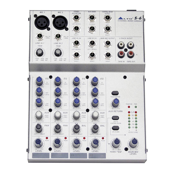
- Page 3 LTO S-6 is an extremely flexible, ultra-low noise 6-channel console, which is the smallest among our range of mixing consoles. It is configured with 2 mono and 2 stereo input channels, each channel is equipped with a variety of key features including a warm, natural sounding EQ, Peak LEDs and PAN/BAL control etc..
-
Page 4: Table Of Contents
TABLE OF CONTENTS 1. INTRODUCTION...4 2. FEATURES...4 3. READY TO START?...4 4. CONTROL ELEMENTS...5 4.1 The MIC/LINE channels 4.2 INPUT LEVEL setting 4.3 STEREO INPUT (CH3 ~ CH6) 4.4 The 3 BANDS EQUALISER 4.5 AUX 4.6 PAN 4.7 PEAK 4.8 LEVEL 4.9 MASTER section 4.10 REAR PANEL 5. -
Page 5: Introduction
MIX or to the other outputs: Control Room and Headphone. Your S-6 is very easy to operate but we advise you to go through each Section of this Manual carefully. In this way you will get the best out of your S-6. -
Page 6: Control Elements
4. CONTROL ELEMENTS MIC 1 BAL OR BAL OR UNBAL UNBAL LINE IN 1 LINE IN 2 TRIM TRIM +15dB -45dB LINE +15dB 60dB 12kHz 12kHz 2.5kHz 80Hz 80Hz POST POST (PRE) (PRE) LEFT RIGHT LEFT PEAK LEVEL LEVEL STEREO AUX SENDS MIC 2 AUX RETURN... -
Page 7: The Mic/Line Channels
4.1 The MIC/LINE channels These are Channel 1 and Channel 2. You can connect balanced, low impedance microphones to the XLR socket. ON the 1/4" phone jack you can connect either a microphone or a line level instrument. You shall never connect an unbalanced microphone to the XLR socket if you do not want to damage both the Microphone and the Mixer. -
Page 8: The 3 Bands Equaliser
Of course a wide number of intermediate positions is available. 4.7 PEAK Inside your S-6 the audio signal is monitored in several different stages and then sent to the PEAK Led. When this Led blinks, it warns you that you are reaching signal saturation and possible distortion. The PEAK Led will blink with a level that is 6dB before actual clipping. -
Page 9: Master Section
-nect microphones when the Phantom Power is on already. - PHANTOM This LED indicates when the Phantom Power is switched on. - PWR This Led indicates when the Power is on in your S-6. PHANTOM PWR PHANTOM PHANTOM AUX RETURN CLIP 2TK TO... - Page 10 - MAIN MIX OUTPUT This stereo output is controlled by the Main Mix Level on the front panel and will send the audio signal to an amplifier. The output level can be varied from - to +15dB. - 2-TRACK IN/OUT Input Use the Tape input if you wish to listen to your Mix from a Taper Recorder or DAT, You can...
-
Page 11: Rear Panel
4.10 REAR PANEL POWER 18VAC~ RATED POWER CONSUMPTION: 11W - POWER This switch is used to turn the Main Power ON and OFF. - 18VAC Used to connect the supplied AC Adapter. CAUTION RISK OF ELECTRIC SHOCK DO NOT OPEN WARNING: SHOCK HAZARD - DO NOT OPEN AVIS: RISQUE DE CHOC ELECTRIQUE... -
Page 12: Installation And Connection
- Connect phantom powered microphones before switching on the +48Volt Phantom Power switch - If you have a power amplifier connected to your S-6 set the Level of the amplifier at no more than 70% - Now, set the CONTROL ROOM/PHONE level at no more than 50%. IN this way you will be able to hear later what you are doing connecting a pair of headphones or a pair of powered studio monitor speakers. - Page 13 b. Some Final Tips on Wiring Configuration You can connect unbalanced equipment to balanced inputs and outputs. Simply follow these schematics. Strain Clamp Strain Clamp 2=Hot(+) 3=Cold(-) Use for Balanced Mic Inputs (For unbalanced use, connect pin 1 to 3) 3-pin XLR Male Plug (seen from soldering side) Ring=Right Signal...
-
Page 14: For The Experts Who Want To Know More
6. FOR THE EXPERTS WHO WANT TO KNOW MORE As we have told you previously in this Manual, the Aux Send Control both on Mono and stereo channels is factory wired as POST-FADER. If you have some skill in electronic components soldering you can modify this setting and have all your AUX sends configured as PRE-FADER. -
Page 15: System Block Diagrams
7. SYSTEM BLOCK DIAGRAMS RIGHT-BUS LEFT-BUS... -
Page 16: Technical Specification
8. TECHNICAL SPECIFICATION Mono input channels Stereo input channels Impedances Equalization Main Mix Section Power supply (AC/AC Adaptor) Physical Microphone input Frequency response Distortion (THD&N) Gain range SNR (Signal to Noise Ratio) Line input Frequency response Distortion (THD&N) Sensitivity range Line input Frequency response Distortion (THD&N) -
Page 17: Warranty
9. WARRANTY 1. WARRANTY REGISTRATION CARD To obtain Warranty Service, the buyer should first fill out and return the enclosed Warranty Registration Card within 10 days of the Purchase Date. All the information presented in this Warranty Registration Card gives the manufacturer a better understanding of the sales status, so as to purport a more effective and efficient after-sales warranty service. - Page 18 SEIKAKU TECHNICAL GROUP LIMITED No. 1, Lane 17, Sec. 2, Han Shi W. Road, Taichung, 401 Taiwan http://www.altomobile.com Tel: 886-4-22313737 email: info@altomobile.com Fax: 886-4-22346757 All rights reserved to ALTO Mobile. Due to continued development in response to customer feedback, product features, specifications and/or internal/external design may be changed without prior notice.