
Related Manuals for Alto AMX-180


Summary of Contents for Alto AMX-180
- Page 1 User's Manual AMX-180/ 18-CHANNEL MIXING CONSOLE/ AMX-180FX WITH DIGITAL EFFECTS www.altoproaudio.com Version 1.0 September 2004 English...
- Page 2 the recommended fuse type as indicated in this SAFETY RELATED SYMBOLS manual. Do not short-circuit the fuse holder. Before replacing the fuse, make sure that the product is CAUTION OFF and disconnected from the AC outlet. RISK OF ELECTRIC SHOCK DO NOT OPEN Protective Ground Before turning the product ON, make sure that it is...
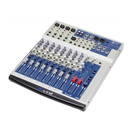
- Page 3 +48 Volt), 4 stereo input channels, 2 stereo aux returns and 2 TK IN. So, in total you have 18 input channels on your AMX-180/AMX-180FX. It is specifically designed for professional application. Seeing is believing, let's meet the LTO AMX-180/AMX-180FX.
-
Page 4: Table Of Contents
TABLE OF CONTENTS 1.INTRODUCTION..............................4 2.FEATURES................................5 3.READY TO START?...............................6 4.CONTROL ELEMENTS............................7 MONO MIC/LINE CHANNELS ........................9 MONO CHANNEL INSERT ..........................9 INPUT LEVEL SETTING ..........................9 LOW CUT SWITCH ............................9 STEREO INPUTS ............................9 +4dBu/-10dBV..............................9 3-BAND EQUALIZER..........................10 AUX SEND CONTROL ..........................10 PAN/BAL CONTROL...........................10 4.10 MUTE/ALT3-4 SWITCH & LED INDICATOR....................10 4.11 SOLO SWITCH &... -
Page 5: Introduction
PA installations. The AMX-180/AMX-180FX mixing console is packed with some key features that can not be found in other consoles of its size: 4 mono (these are provided with ultra low noise microphone preamplifiers and phantom power at +48 Volt) and 4 stereo input channels, and each of them is provided with a 3 bands equalizer for HI, MID and LOW controls;... -
Page 6: Features
2. FEATURES The AMX-180/AMX-180FX mixing console is designed for professional application. It will provide the following features: The common features: 5 MIC input channels with gold plated XLR and balanced LINE inputs 4 stereo input channels with balanced TRS jacks... -
Page 7: Ready To Start
3.3 Before turning on the AMX-180/AMX-180FX you shall connect it to a power amplifier and turn-on the mixer BEFORE the power amplifier. Once you have finished your working session you shall turn the mixer off AFTER the power amplifier. -
Page 8: Control Elements
4. CONTROL ELEMENTS AMX-180 MIC 1 MIC 2 MIC 3 MIC 4 2-TRACK IN/OUT STEREO AUX RETURNS MAIN MIX OUTPUT(BAL/UNBAL) -180 MIC +4dBu MIC +4dBu MIC +4dBu MIC +4dBu J.T. J.T. J.T. J.T. J.T. J.T. J.T. J.T. MAIN OUTPUT MAIN OUTPUT... - Page 9 AMX-180FX MIC 1 MIC 2 MIC 3 MIC 4 2-TRACK IN/OUT STEREO AUX RETURNS MAIN MIX OUTPUT(BAL/UNBAL) -180 MIC +4dBu MIC +4dBu MIC +4dBu MIC +4dBu J.T. J.T. J.T. J.T. J.T. J.T. J.T. J.T. MAIN OUTPUT MAIN OUTPUT 18-CHANNEL MIXING CONSOLE LEFT(MONO) LEFT LEVEL...
-
Page 10: Mono Mic/Line Channels
4.1 MONO MIC/LINE CHANNELS These are channel 1 through channel 4. You can connect balanced, MIC 1 low impedance microphones or a low level signal to the XLR socket. On the 1/4" line jack you can connect either a microphone or a line level instrument such as synthesizers, drum machines, effect pro- J.T. -
Page 11: 3-Band Equalizer
4.7 3-BAND EQUALIZER A 3-band equalizer is provided for each input channel with a wide range of frequency adjustment. - HI This is the treble control. You can use it to get rid of high frequency noises or to boost the sound of cymbals or the high harmonics 12kHz of the human voice. -
Page 12: Peak Led
Note: in AMX-180 model, the returned signal of AUX RETURN 1 will also be routed to AUX RETURN 2 if there is no signal feeding to AUX RETURN 2 sockets, The signal is summed, or mixed in to the main L/R mix bus. -
Page 13: Ctrl Room Output
4.19 CTRL ROOM OUTPUT These 1/4" sockets are used to send the control room signal to the studio monitor speakers or a second set of PA. 4.20 ALT OUTPUT These 1/4" sockets are unbalanced outputs, the signal level to the ALT OUTPUT is adjusted by ALT 3-4 rotary on the front panel. -
Page 14: Power Led
4.30 POWER LED This LED indicates when the power is on in your AMX-180/AMX-180FX. 4.31 SOLO MODE SWITCH This button provides two modes: up for PFL (Pre-Fader-Listen) mode, down for AFL (After-Fader-Listen) mode. Engage the button, the output signal of soloed channel will follow the TRIM, EQ, FADER and PAN/BAL control, and the SOLO ACTIVE LED illuminates. -
Page 15: Rear Panel Description
4.38 REAR PANEL DESCRIPTION CAUTION MODEL RISK OF ELECTRIC SHOCK DO NOT OPEN WARNING: SHOCK HAZARD - DO NOT OPEN AVIS: RISQUE DE CHOC ELECTRIQUE - NE PAS OUVRIR 18VAC~ SERIAL POWER PHANTOM RATED POWER CONSUMPTION: 25W - POWER ON/OFF SWITCH This switch is used to turn the main power ON and OFF. -
Page 16: Installation And Connection
5. INSTALLATION AND CONNECTION Ok, you have got to this point and you are now in the position to successfully operate your AMX-180/AMX-180FX. However, we advise you to read carefully the following section to be the real master of your own mixer. Not paying... - Page 17 5.1. Some Final Tips on Wiring Configuration You can connect unbalanced equipment to balanced inputs and outputs. Simply follow these schemes. Ring=Right Signal Sleeve Ring Strain Clamp Tip=Left Signal Sleeve=Ground/Screen Use for Headphone, Stereo Return 1/4" Stereo (TRS) Jack Plug Sleeve Tip=Signal Strain Clamp...
- Page 18 Ring=Return Signal (Connected together) To Channel Insert Sleeve=Ground/Screen Tip=Signal To Tape or FX Input Sleeve=Ground/Screen 'Tapped' Connection Direct Output Lead (Enables the Insert to be used as a Direct Output while maintaining the channel signal flow) To Processor Input Sleeve=Ground/Screen Tip=Send Signal To Channel Insert Ring=Return Signal...
-
Page 19: For The Experts Who Want To Know More
6. FOR THE EXPERTS WHO WANT TO KNOW MORE As we have told you previously in this manual, the AUX SEND2 control both on mono and on stereo channels is factory wired as POST-FADER. If you have some skill in electronic components soldering you can modify this setting and have all your AUX SENDS configured as PRE-FADER. -
Page 20: Preset List
7. PRESET LIST (For AMX-180FX Model) 01. VOCAL1 Pre-delay Rev. Type Hi Damp Rev Time Room Size 1.00 Hall Tape 1.00 Spring 4.50 3.60 Plate Spring 1.20 3.60 Hall Plate 1.50 Plate Spring 2.40 Tape 0.90 1.50 Plate 1.00 Hall Spring 1.00 Tape... - Page 21 4.00 -0.96 4.00 -12.00 4.00 -0.96 4.00 -12.00 3.60 -0.96 3.60 -12.00 3.60 -0.96 3.60 -12.00 04. SMALL HALL Pre-delay Hi Damp Rev Time Room Size Rev level 2.90 -0.96 2.90 -12.00 2.90 -0.96 2.90 -12.00 2.10 -0.96 2.10 -12.00 2.10 -0.96 2.10...
- Page 22 06. SMALL ROOM Pre-delay Hi Damp Rev Time Room Size Rev level 2.10 -0.96 2.10 -12.00 2.10 -0.96 2.10 -12.00 1.50 -0.96 1.50 -12.00 1.50 -0.96 1.50 -12.00 1.00 -0.96 1.00 -12.00 1.00 -0.96 1.00 -12.00 0.70 -0.96 0.70 -12.00 0.70 -0.96 0.70...
- Page 23 3.60 -0.96 3.60 -12.00 2.90 -0.96 2.90 -12.00 2.10 -0.96 2.10 -12.00 1.30 -0.96 1.30 -12.00 09. SPRING REVERB Pre-delay Hi Damp Rev Time Room Size Rev level -0.96 -12.00 4.50 -0.96 4.50 -12.00 -0.96 -12.00 3.60 -0.96 3.60 -12.00 2.90 -0.96 2.90...
- Page 24 11. STEREO DELAY Delay Right Delay Left F.B. Right F.B. 12. FLANGER Mod. Freq Pitch. Depth Left F.B. Right F.B. 2.79 2.52 2.33 2.25 2.10 1.99 1.75 1.61 1.34 1.22 1.00 0.80 0.65 0.54 0.42 0.16 13. CHORUS Mod. Freq. Pitch.
- Page 25 2.33 -3(0) 1.99 -3(0) 1.70 -3(0) 1.35 -2(0) 1.00 -2(0) 0.50 -2(0) 14. REVERB+DELAY Rev Time Room Size Left Delay Right Delay Left F.B. Right F.B. Rev level 2.90 2.90 2.90 2.90 2.40 2.40 2.40 2.40 2.10 2.10 1.50 1.50 1.50 1.50 1.00...
- Page 26 16. REVERB+CHORUS Rev Time Room Size Mod. Freq. Pitch. Depth Left F.B. Rev level 2.90 4.74 2.90 4.12 2.90 3.67 2.90 3.02 2.90 2.63 2.90 1.99 2.90 1.35 2.90 0.50 1.50 4.74 1.50 4.12 1.50 3.67 1.50 3.02 1.50 2.63 1.50 1.99 1.00...
-
Page 27: System Block Diagram
8. SYSTEM BLOCK DIAGRAM LOGIC SEND SEND SOLO(PFL) SOLO(PFL) AFL-R AFL-L AUX-2 AUX-2 AUX-1 AUX-1 ALT-4(R ALT-4(R ALT-3(L) ALT-3(L) RIGHT-BUS RIGHT-BUS LEFT-BUS LEFT-BUS... -
Page 28: Technical Specification
9. TECHNICAL SPECIFICATION Mono input channels Microphone input Electronically balanced ,discrete input configuration Frequency response 10Hz to 55KHz, 3dB Distortion (THD&N) 0.005% at +4dBu, 1KHz Gain range 0dB to 44dB(MIC) SNR (Signal Noise Rated) 115dB Line input Electronically balanced Frequency response 10Hz to 55KHz, 3dB Distortion (THD&N) 0.005% at +4dBu, 1KHz... -
Page 29: Warranty
10. WARRANTY 10.1 WARRANTY REGISTRATION CARD To obtain Warranty Service, the buyer should first fill out and return the enclosed Warranty Registration Card within10 days of the Purchase Date. All the information presented in this Warranty Registration Card gives the manufacturer a better understanding of the sales status, so as to purport a more effective and efficient after-sales warranty service. - Page 30 No.1, Lane 17, Sec. 2, Han Shi West Road, Taichung, 401 TAIWAN http://www.altoproaudio.com Tel:886-4-22313737 email: alto@altoproaudio.com Fax:886-4-22346757 All rights reserved to ALTO. All features and content might be changed without prior notice. Any photocopy, translation, or reproduction of part of this manual without written permission is forbidden. Copyright...