
Related Manuals for Alto L-8


Summary of Contents for Alto L-8
- Page 1 User's Manual 8-CHANNEL MIXING CONSOLE WITH DIGITAL EFFECTS www.altoproaudio.com Version 1.2 August 2004 English...
- Page 2 the recommended fuse type as indicated in this SAFETY RELATED SYMBOLS manual. Do not short-circuit the fuse holder. Before replacing the fuse, make sure that the product is CAUTION OFF and disconnected from the AC outlet. RISK OF ELECTRIC SHOCK DO NOT OPEN Protective Ground This symbol, wherever used, alerts you to the pre-...
- Page 3 LTO L-8 8-Channel Mixing Console with Digital Effects has 4 mono (these are provided with Ultra Low Noise microphone preamplifiers and Phantom Power at +48 Volt) and 2 stereo input channels, and each of them is provided with a 3 bands graphic equliser for HI, MID and LOW controls.
-
Page 4: Table Of Contents
TABLE OF CONTENTS 1.INTRODUCTION..............................4 2.FEATURES................................5 3.READY TO START?...............................6 4.CONTROL ELEMENTS............................7 The mono MIC/LINE channels........................8 INPUT LEVEL setting...........................8 LOW-CUT FILTER............................8 STEREO INPUTS............................9 The 3 BANDS EQUALISER..........................9 AUX SEND..............................10 PAN................................10 PEAK................................10 LEVEL.................................10 4.10 INSERT...............................10 4.11 MASTER SECTION ...........................11 -MAIN MIX LEVEL -LED METER -2 TRACK signal path -AUX RETURN -POWER LED... -
Page 5: Introduction
2-Track inputs assignable to main mix, control room / headphone outputs. Your L-8 is very easy to operate but we advise you to go through each Section of this Manual carefully. In this way you will get the best out of your L-8. -
Page 6: Features
2. FEATURES The L-8 8 Channel Mixing Console with Digital Effects is designed for professional appliance. It will provide the following features: 5 MIC input channels with gold plated XLRs and balanced LINE input 2 stereo input channels with balanced TRS jacks... -
Page 7: Ready To Start
3.3 Before turning on the L-8 you shall connect it to a power amplifier and turn-on the mixer BEFORE the power amplifier. Once you have finished your working session you shall turn the mixer off AFTER the power amplifier. -
Page 8: Control Elements
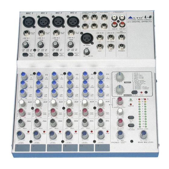
4. CONTROL ELEMENTS MIC 1 MIC 2 MIC 3 MIC 4 STEREO AUX RETURN AUX SEND 2-TRACK IN/OUT LEFT(MONO) RIGHT 8-CHANNEL MIXING CONSOLE DIGITAL EFFECTS LEFT WITH RIGHT TAPE IN TAPE OUT BAL OR BAL OR BAL OR BAL OR LINE IN 5/6 LINE IN 7/8 FOOTSWITCH... -
Page 9: The Mono Mic/Line Channels
4.1 The mono MIC/LINE channels These are Channel 1 through Channel 4. You can connect balanced, low im- MIC 1 pedance microphones to the XLR socket. On the 1/4" phone jack you can connect either a microphone or a line level instrument. You shall never connect an unbalanced microphone to the XLR socket if you do not want to damage both the Microphone and the Mixer. -
Page 10: Stereo Inputs
4.4 STEREO INPUTS LINE IN 5/6 LINE IN 7/8 These are Channel 5 through 8. They are organised in stereo pair and they are provided with 1/4" TRS phone sockets. LEFT (MONO) LEFT (MONO) If you connect only the left jack, the input will operate MIC (MONO) in mono mode. -
Page 11: Aux Send
LEFT RIGHT 4.8 PEAK Inside your L-8 the audio signal is monitored in several different stages PEAK and then sent to the PEAK Led. When this Led blinks, it warns you that you are reaching signal saturation and possible distortion. The PEAK Led will blink with a level that is 6dB before actual clipping. -
Page 12: Master Section
- POWER LED This LED indicates when the Power is on in your L-8. - PHANTOM LED This LED indicates when the Phantom Power is switched on. -
Page 13: Bit Digital Effects
- 24 BIT DIGITAL EFFECTS PRESETS 1. VOCAL 1 2. VOCAL 2 3. LARGE HALL Adjust this knob to select the right effect you wish 4. SMALL HALL 5. LARGE ROOM to perform. There are total 16 options for you: several 6. -
Page 14: 2-Track In/Out
- AC INLET WITH FUSE HOLDER Use it to connect your L-8 to the Main AC with the supplied AC cord. Please check the Voltage available in your Country and make sure the Voltage for your L-8 before attempting to connect your L-8 to the Main AC. -
Page 15: Installation And Connection
5. INSTALLATION AND CONNECTION Ok, you have got to this point you are now in the position to successfully operate your L-8. However, we advise you to read carefully the following section to be the real Master of your own Mix. Not paying attention enough to the Input signal level, to the routing of the signal and the assignment of the signal will result in unwanted distortion, a corrupted signal or no sound at all. - Page 16 5.1 SOME FINAL TIPS ON WIRING CONFIGURATION You can connect unbalanced equipment to balanced inputs and outputs. Simply follow these schematics. Ring=Right Signal Sleeve Ring Strain Clamp Tip=Left Signal Sleeve=Ground/Screen Use for Headphone, Stereo Return 1/4" Stereo (TRS) Jack Plug Sleeve Tip=Signal Strain Clamp...
- Page 17 Ring=Return Signal (Connected together) To Channel Insert Sleeve=Ground/Screen Tip=Signal To Tape or FX Input Sleeve=Ground/Screen 'Tapped' Connection Direct Output Lead (Enables the Insert to be used as a Direct Output while maintaining the channel signal flow) To Processor Input Sleeve=Ground/Screen Tip=Send Signal To Channel Insert Ring=Return Signal...
-
Page 18: For The Experts Who Want To Know More
6. FOR THE EXPERTS WHO WANT TO KNOW MORE As we have told you previously in this Manual, the Aux Send 2 Control both on Mono and on stereo channels is factory wired as POST-FADER. If you have some skill in electronic components soldering you can modify this setting and have all your AUX sends configured as PRE-FADER. -
Page 19: Preset List
7. PRESET LIST 01. VOCAL1 Pre-delay Rev. Type Hi Damp Rev Time Room Size 1.00 Hall Tape 1.00 Spring 4.50 3.60 Plate Spring 1.20 3.60 Hall Plate 1.50 Plate Spring 2.40 Tape 0.90 1.50 Plate 1.00 Hall Spring 1.00 Tape 2.10 4.50 Plate... - Page 20 4.00 -0.96 4.00 -12.00 4.00 -0.96 4.00 -12.00 3.60 -0.96 3.60 -12.00 3.60 -0.96 3.60 -12.00 04. SMALL HALL Pre-delay Hi Damp Rev Time Room Size Rev level 2.90 -0.96 2.90 -12.00 2.90 -0.96 2.90 -12.00 2.10 -0.96 2.10 -12.00 2.10 -0.96 2.10...
- Page 21 06. SMALL ROOM Pre-delay Hi Damp Rev Time Room Size Rev level 2.10 -0.96 2.10 -12.00 2.10 -0.96 2.10 -12.00 1.50 -0.96 1.50 -12.00 1.50 -0.96 1.50 -12.00 1.00 -0.96 1.00 -12.00 1.00 -0.96 1.00 -12.00 0.70 -0.96 0.70 -12.00 0.70 -0.96 0.70...
- Page 22 3.60 -0.96 3.60 -12.00 2.90 -0.96 2.90 -12.00 2.10 -0.96 2.10 -12.00 1.30 -0.96 1.30 -12.00 09. SPRING REVERB Pre-delay Hi Damp Rev Time Room Size Rev level -0.96 -12.00 4.50 -0.96 4.50 -12.00 -0.96 -12.00 3.60 -0.96 3.60 -12.00 2.90 -0.96 2.90...
- Page 23 11. STEREO DELAY Delay Right Delay Left F.B. Right F.B. 12. FLANGER Mod. Freq Pitch. Depth Left F.B. Right F.B. 2.79 2.52 2.33 2.25 2.10 1.99 1.75 1.61 1.34 1.22 1.00 0.80 0.65 0.54 0.42 0.16 13. CHORUS Mod. Freq. Pitch.
- Page 24 2.33 -3(0) 1.99 -3(0) 1.70 -3(0) 1.35 -2(0) 1.00 -2(0) 0.50 -2(0) 14. REVERB+DELAY Rev Time Room Size Left Delay Right Delay Left F.B. Right F.B. Rev level 2.90 2.90 2.90 2.90 2.40 2.40 2.40 2.40 2.10 2.10 1.50 1.50 1.50 1.50 1.00...
- Page 25 16. REVERB+CHORUS Rev Time Room Size Mod. Freq. Pitch. Depth Left F.B. Rev level 2.90 4.74 2.90 4.12 2.90 3.67 2.90 3.02 2.90 2.63 2.90 1.99 2.90 1.35 2.90 0.50 1.50 4.74 1.50 4.12 1.50 3.67 1.50 3.02 1.50 2.63 1.50 1.99 1.00...
-
Page 26: System Block Diagrams
8. SYSTEM BLOCK DIAGRAMS... -
Page 27: Technical Specification
9. TECHNICAL SPECIFICATION Mono input channels Microphone input electronically balanced, discrete input configuration Frequency response 10Hz to 55kHz, + Distortion (THD & N) 0.005% at +4dBu, 1kHz Gain range 0dB to 60dB (MIC) SNR (Signal to Noise Ratio) 115dB Line input electronically balanced Frequency response 10Hz to 55kHz, +... - Page 28 Power supply Main voltage USA/Canada 100 120V~, 60Hz Europe 210 240V~, 50Hz U.K./Australia 240V~, 50Hz Power Consumption 25 watts Fuse 100 120V~ : T500mAL 210 240V~ : T250mAL Main connection Standard IEC receptacle Physical Dimension (W D H) 245mm 268mm 24/73mm (9.64" 10.54" 0.94"/2.87") Net weight 3.0Kg (6.62lb) Shipping weight...
-
Page 29: Warranty
10. WARRANTY 1. WARRANTY REGISTRATION CARD To obtain Warranty Service, the buyer should first fill out and return the enclosed Warranty Registration Card within 10 days of the Purchase Date. All the information presented in this Warranty Registration Card gives the manufacturer a better understanding of the sales status, so as to purport a more effective and efficient after-sales warranty service. - Page 30 No.1, Lane 17, Sec. 2, Han Shi West Road, Taichung, 401 TAIWAN http://www.altoproaudio.com Tel:886-4-22313737 email: alto@altoproaudio.com Fax:886-4-22346757 All rights reserved to ALTO. All features and content might be changed without prior notice. Any photocopy, translation, or reproduction of part of this manual without written permission is forbidden. Copyright...