Yamaha DTX-Multi 12 Service Manual
Electronic percussion pad
Hide thumbs
Also See for DTX-Multi 12:
- Firmware update manual (4 pages) ,
- Owner's manual (116 pages) ,
- Manual (24 pages)
Table of Contents
Advertisement
Quick Links
QQ
3 7 63 1515 0
TE
L 13942296513
www
• OPTION(別売品)
MAT1
.
ED
011962
DTX-MULTI12 20091125-94500
MAT1 20091125-5250
http://www.xiaoyu163.com
x
ao
u163
y
i
2 9
8
SERVICE MANUAL
SERVICE MANUAL
Q Q
3
6 7
1 3
1 5
CONTENTS(目次)
Specifications(総合仕様) ...................................3/4
Panel Layout(パネルレイアウト) ...........................5
Circuit Board Layout (ユニットレイアウト) ..........6
Wiring (結線図) ............................................................8
Disassembly Procedure(分解手順) ...................9
LSI PIN DESCRIPTION(LSI 端子機能表) ..................14
IC BLOCK DIAGRAM(IC ブロック図) .......................16
Circuit Boards(シート基板図) ............................18
Test Program(テストプログラム) ..................24/37
(ファイルのセーブ&ロード) ..................................50/53
Updating(アップデート) ........................................56
FORMAT OF USB MEMORY DEVICE
(USB 記憶装置のフォーマット(初期化) ) ..................58
(ファクトリーセット) ..................................................59
Display Messages(メッセージリスト) ..........60/62
Boot Sequence(起動シーケンス) ...................64/65
BLOCK DIAGRAM(ブロックダイアグラム)
Circuit Diagram(回路図)
co
.
Copyright (c) Yamaha Corporation. All rights reserved. PDF
9 4
2 8
0 5
8
2 9
9 4
2 8
m
HAMAMATSU, JAPAN
9 9
9 9
'09.11
&
Advertisement
Table of Contents

Related Manuals for Yamaha DTX-Multi 12


Summary of Contents for Yamaha DTX-Multi 12
- Page 1 (USB 記憶装置のフォーマット(初期化) ) ....58 INITIAL FACTORY SETTING (ファクトリーセット) ..........59 DISPLAY MESSAGES(メッセージリスト) ..60/62 BOOT SEQUENCE(起動シーケンス) ....64/65 PARTS LIST BLOCK DIAGRAM(ブロックダイアグラム) • OPTION(別売品) CIRCUIT DIAGRAM(回路図) u163 MAT1 011962 HAMAMATSU, JAPAN DTX-MULTI12 20091125-94500 Copyright (c) Yamaha Corporation. All rights reserved. PDF ’09.11 MAT1 20091125-5250 &...
-
Page 2: Saving Data
IMPORTANT NOTICE This manual has been provided for the use of authorized Yamaha Retailers and their service personnel. It has been assumed that basic service procedures inherent to the industry, and more specifically Yamaha Products, are already known and understood by the users, and have therefore not been restated. -
Page 3: Specifications
Power Consumption 6W (DTXM12 and PA-150 adaptor) Size and weight 345 (w) x 319 (d) x 96 (h) mm; 3.3 kg Power adaptor (PA-5D/PA-150 or an equivalent recommended by Yamaha), Package Contents Owner’s Manual (this booklet), Data List booklet, DVD-ROM u163... - Page 4 DTX-MULTI 12 3 7 63 1515 0 総合仕様 パッド部 パッド数 外部入力 5 (3ゾーン対応×1, モノラル× 4) 音源部 最大同時発音数 64音 波形メモリー 100MB相当(16bitリニア換算) ボイス数 ドラム/パーカッション:1,061音色 キーボード:216音色 ドラムキット数 プリセット:50キット ユーザー:200キット エフェクター バリエーション×42タイプ、コーラス×6タイプ、リバーブ×6タイプ、マスター EQ(5バンド) トリガー部 パッドファンクション ドラムキットINC/DEC、パターンINC/DEC、テンポ INC/DEC、タップテンポ、クリックON/ OFF、コントロールチェンジ送信 ウェーブ 読み込み可能ウェーブ数 ウェーブデータビット 16bit 波形メモリー...
-
Page 5: Panel Layout(パネルレイアウト
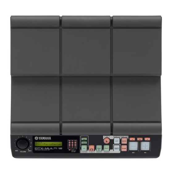
DTX-MULTI 12 3 7 63 1515 0 PANEL LAYOUT(パネルレイアウト) • Front Panel(フロントパネル) ≤≤≤≤≤YAMAHA <<DTX-MULTI≤12>> o !0 • Side Panel(サイドパネル) L 13942296513 • Rear Panel(リアパネル) #0 #1 q [VOLUME] dial !7 [+/INC] button q VOLUME (マスターボリューム) !7 [+/INC] ボタン w Display !8 [USB TO DEVICE] port w LCD 画面... -
Page 6: Circuit Board Layout (ユニットレイアウト
DTX-MULTI 12 3 7 63 1515 0 CIRCUIT BOARD LAYOUT(ユニットレイアウト) <Top view> PAD UNIT R (パッドユニットR) PAD UNIT F (パッドユニットF) FRONT CASE ASSEMBLY L 13942296513 (フロントAss’ y) <Top view> u163... - Page 7 DTX-MULTI 12 3 7 63 1515 0 • FRONT CASE ASSEMBLY (フロントAss’ y) LCD MODULE <Bottom view> (LCDモジュール) • PAD UNIT R (F) (パッドユニットR (F) ) PAD ASSEMBLY (パッドユニット組立品) <Bottom view> L 13942296513 • PAD ASSEMBLY (パッドユニット組立品) PAD SHEET SWITCH (パッドシートSW)...
- Page 8 http://www.xiaoyu163.com 3 7 6 3 1 5 1 5 0 to SENSOR UNIT ST (PAD3) to SENSOR UNIT CT (PAD2) to SENSOR UNIT ST (PAD1) to PAD SHEET SWITCH (Rear side) to PAD SHEET SWITCH (Front side) to SENSOR UNIT ST (PAD4) CN304 (8P) to SENSOR UNIT CT (PAD5)
-
Page 9: Disassembly Procedure(分解手順
DTX-MULTI 12 3 7 63 1515 0 DISASSEMBLY PROCEDURE(分解手順) Precautions(注意事項) Notes on Flat Cable ※ フラットケーブルの注意 Contacts are visible from the back. Pay attention not to 接点が裏面から透けて見えます。コネクタにケーブルの表・ insert and install the cable to the connector inversely. 裏を逆に差込まないように注意して取り付けてください。 (Photo 1) (写真... - Page 10 DTX-MULTI 12 3 7 63 1515 0 PAD UNIT F パッドユニット F (所要時間 : 約 3 分) (Time required: About 3 minutes) Remove the pad unit R. (See procedure 1.) パッドユニット R を外します。 (1 項参照) Remove the four (4) screws marked [150B] and six [150B] のネジ...
- Page 11 DTX-MULTI 12 3 7 63 1515 0 Remove the two (2) screws marked [JK40] and fi ve (5) [JK40] のネジ 2 本と U 字金具 5 個を外して、 JK シー angle brackets, U and separate the JK circuit board and トとシールド JK を分離します。 (図 4)...
- Page 12 DTX-MULTI 12 3 7 63 1515 0 PN Circuit Board, LCD Module, PN シート、LCD モジュール、VR シート VR Circuit Board パッドユニット R を外します。 (1 項参照) Remove the pad unit R. (See procedure 1.) パッドユニット F を外します。 (2 項参照) Remove the pad unit F. (See procedure 2.) フロント...
- Page 13 DTX-MULTI 12 3 7 63 1515 0 Sensor Unit CT, Sensor Unit ST, センサユニット CT、センサユニット ST、 Pad Sheet Switch パッドシート SW (所要時間 : 各約 2 分) (Time required: About 2 minutes each) ※ ここでは、パッドユニット R 側の手順を記載します。 パッドユニット F 側も同様に外すことができます。...
-
Page 14: Lsi Pin Description(Lsi 端子機能表
DTX-MULTI 12 3 7 63 1515 0 LSI PIN DESCRIPTION(LSI 端子機能表) R8A02032BG (X8810A00) CPU (SWX02) DM: IC8 OUTER OUTER NAME FUNCTION NAME FUNCTION Ground VSSPLL PLL analog ground ADC analog input 2 Wave memory data bus 6 ADC analog input 1... - Page 15 DTX-MULTI 12 3 7 63 1515 0 OUTER OUTER NAME FUNCTION NAME FUNCTION MA15 Wave memory address bus 15 Parallel port A6 MA16 Wave memory address bus 16 Parallel port A7 MA17 Wave memory address bus 17 VCCQ Power supply +3.3 V...
-
Page 16: Ic Block Diagram(Ic ブロック図
DTX-MULTI 12 3 7 63 1515 0 IC BLOCK DIAGRAM(IC ブロック図) SN74LV14PWR (X6688A0R) SN74LVC1G32DCKR (X5825A00) SN74LV245APWR (X3693A0R) DM: IC5 JK: IC319 JK: IC333335 JK: IC307 2-Input OR Gate TC74VHCT245AF (XV242B00) Hex Inverter PN: IC501 Octal 3-State Bus Transceiver IN B... - Page 17 DTX-MULTI 12 3 7 63 1515 0 TC4066BF(EL,N,F) (XD103A00) R5520H001B-T1-F (X7569A00) JK: IC316 DM: IC16 Quad Bilateral Switch USB High-Side Power Switch IN/OUT1 OUT/IN1 CONT1 OUT/IN2 CONT4 IN/OUT2 IN/OUT4 GATE CURRENT CONTROL LIMIT CONT2 OUT/IN4 FLAG CONT3 OUT/IN3 DELAY...
-
Page 18: Circuit Boards(シート基板図
DTX-MULTI 12 3 7 63 1515 0 BD9040FV (YA575A00) JK: IC306 DC-DC Converter 5.5V Reg 3.0V Reg EN_SS VREG5 VREG3 – + – BOOT O/S Check OUTH – – UVLO UVLO 3.8V 2.5V – COMP DGND – OUTL BOOT... - Page 19 DTX-MULTI 12 3 7 63 1515 0 PN Circuit Board 13-17/ FOOT SW/ HH CTRL VOICE MIDI WAVE UTILITY L 13942296513 SHIFT EXIT to DM-CN5 STORE ENTER – < > u163 Component side(部品側) Pattern side(パターン側) 2NA-WR84770...
-
Page 20: Dtx-Multi
DTX-MULTI 12 3 7 63 1515 0 JK Circuit Board to SENSOR UNIT CT (PAD2) to SENSOR UNIT CT (PAD5) to SENSOR UNIT ST (PAD6) to SENSOR UNIT ST (PAD1) to SENSOR UNIT ST (PAD3) to SENSOR UNIT ST (PAD4) - Page 21 DTX-MULTI 12 3 7 63 1515 0 VR Circuit Board MASTER VOLUME Component side(部品側) Pattern side(パターン側) to PAD SHEET SWITCH (Rear side) to PAD SHEET SWITCH (Front side) to DM-CN8 to DM-CN6 L 13942296513 HH CTRL AUX IN L/MONO...
- Page 22 DTX-MULTI 12 3 7 63 1515 0 JK Circuit Board L 13942296513 B’ DM Circuit Board to JK-CN302 to JK-CN303 to JK-CN301 to PN-CN501 u163 not installed not installed to LCD MODULE Component side(部品側) JK: 2NA-WR84760 DM: 2NA-WR84750...
- Page 23 DTX-MULTI 12 3 7 63 1515 0 L 13942296513 B’ Pattern side(パターン側) DM Circuit Board TO DEVICE TO HOST u163 Pattern side(パターン側) JK: 2NA-WR84760 DM: 2NA-WR84750...
-
Page 24: Test Program
DTX-MULTI 12 3 7 63 1515 0 TEST PROGRAM Tests item list Item Outline Test Code LCD,LED Check visually if the LCD and LED are turned on. A0 01 00 Panel SW Operate the panel switches and check operation. - Page 25 MANUAL MODE: · Press the [EXIT] button to go to test item 44 “Exit”. Turn on the power to DTX-MULTI 12 while holding down · Press the [ENTER] button and the following screen will the [KIT] and [ENTER] buttons simultaneously.
- Page 26 DTX-MULTI 12 3 7 63 1515 0 Send following commands to change limit value of each test 02. Panel SW item 03 to 14 “PadSW&Xt IN test”, 17 to 21 “Trigger IN test” (refer to page 27), 36 to 41 “Trig(S) IN test” (refer to [Test Code] page 34) when the unit is ready for MIDI test code.
- Page 27 DTX-MULTI 12 3 7 63 1515 0 [How to quit test] 17. Trigger IN13, 18. Trigger IN14, In case of OK, press the [+/INC] button to proceed to the next 19. Trigger IN15, 20. Trigger IN16, test. 21. Trigger IN17 In case of NG, press the [EXIT] button 5 times and the following screen will appear.
- Page 28 DTX-MULTI 12 3 7 63 1515 0 [Judgment indication] 17:Trigger IN13 In case of OK: XtIN ○○:XX 22:HiHat XtIN ○○XX: NG due to signal leak of XX to the channel ○○ In case of NG: None 17:Trigger IN13 [MIDI code output for judgment result]...
- Page 29 DTX-MULTI 12 3 7 63 1515 0 [How to quit test] 25. MIDI In case of OK, press the [+/INC] button to proceed to the next test. [Test Code] Press the [EXIT] button to return to the “test number selection A0 19 00 screen”...
- Page 30 DTX-MULTI 12 3 7 63 1515 0 Press the [ENTER] button after the following screen appeared. [Test method] Press the [ENTER] button to execute the test. 27:USB-ToHost After the screen changes to the following indication, insert a ConnectUSB![ENT] USB memory and press the [ENTER] button again.
- Page 31 DTX-MULTI 12 3 7 63 1515 0 [Check item] [Test method] · [OUTPUT L/MONO]: Frequency: 1 kHz ± 1.5 Hz Press the [ENTER] button to execute the test. Waveform: Sine wave The [MASTER] volume and [PHONES] volume should be set Level: +3.0 ±...
- Page 32 DTX-MULTI 12 3 7 63 1515 0 [Test method] [Initial indication] Press the [ENTER] button to execute the test. 31:AUX IN(ph) Input sine wave to the Lch and Rch of the [AUX IN] terminal Press [ENTER] with standard monaural plug connected to the [OUTPUT] terminal and measure output waveform level and distortion of the [OUTPUT L/MONO] and [OUTPUT R] terminals.
- Page 33 DTX-MULTI 12 3 7 63 1515 0 [Check item] [MIDI code output for judgment result] Check the test result indicated on the LCD. OK: A0 21 02 NG: A0 21 03 [Judgment indication] In case of OK: [How to quit test] Press the [+/INC] button to proceed to next test.
- Page 34 DTX-MULTI 12 3 7 63 1515 0 35. RAM [Test contents] Add signal looped from the [PHONES] terminal to the JK circuit board PH connector (CN305.310) and check the [Test Code] A0 23 00 followings: · The inputted signal is inputted to the CPU at the proper value ·...
- Page 35 DTX-MULTI 12 3 7 63 1515 0 44. Exit 36:Trig(S) IN04 BadCR:XX [Test Code] A0 2C 00 BAD CR XX: NG due to waveform attenuation value of XX [Initial indication] [MIDI code output for judgment result] 44:Exit OK: A0 XX 02...
- Page 36 DTX-MULTI 12 3 7 63 1515 0 Cycle the power to DTXM12 and check that the ON/OFF click noise meets the following requirements with the [MASTER] and [PHONES] volume set to MAX. [OUTPUT L/MONO]: 500 mVpp or less (load of 10 Ω) [OUTPUT R]: 500 mVpp or less (load of 10 Ω)
- Page 37 DTX-MULTI 12 3 7 63 1515 0 テストプログラム テスト項目一覧 番号 項目 概要 テストコード LCD,LED LCD と、LED の点灯を、目視で確認します。 A0 01 00 Panel SW パネルスイッチを操作し、動作を確認します。 A0 02 00 PadSW&Xt IN01 A0 03 00 PadSW&Xt IN02 A0 04 00 PadSW&Xt IN03 A0 05 00 PadSW&Xt IN04...
- Page 38 ※ 特に指示のない限り、これらの値を変更する必要は ありません。 [STORE] ボタンを押すと、 テスト項目 43. FactorySet (48 ページ参照)が実行され、下記画面が表示されます。 A. テストエントリー MANUAL MODE: 44:Exit ● [KIT] ボタンと [ENTER] ボタンを同時に押しながら、 [EXIT]or[ENT] DTX-MULTI 12 の電源を立ち上げます。 L 13942296513 オープニング画面終了後、下記バージョン画面が表示 · [EXIT] ボタンを押すと、テスト項目 44. Exit に進み されます。 ます。 · [ENTER] ボタンを押すと、以下の画面が表示されま B:*.*** す。 F:*.*** W:*.***...
- Page 39 DTX-MULTI 12 3 7 63 1515 0 バージョン画面が数秒間表示された後、下記パッド検 [ 判定結果の MIDI コード出力 ] 査用閾値設定画面へ移動します。 なし at:36-41 x:02,10 [ テストの終了方法 ] cr:0c-1f sw&x:04 [EXIT] ボタンを押して「テストナンバー選択画面」に戻 ります。 この画面が表示されたら、MIDI テストコード待ちと [+/INC] ボタンを押して、次のテストに進みます。 なります。 画面に表示された、テスト項目 03. ∼ 14. PadSW&Xt IN テスト、 17. ∼ 21. Trigger IN テスト (40 ページ参照) 、...
- Page 40 DTX-MULTI 12 3 7 63 1515 0 [ 判定結果の MIDI コード出力 ] [ 判定結果の MIDI コード出力 ] OK: A0 XX 02 OK: A0 02 02 NG: A0 XX 03 NG: なし XX は、テストコードを参照してください。 [ テストの終了方法 ] [ テストの終了方法 ] OK の時は、[+/INC] ボタンを押して次のテストに進み...
- Page 41 DTX-MULTI 12 3 7 63 1515 0 [ 判定結果の表示 (例) ] その後コントローラを離して最大値を正常に認識するこ OK の時: とを確認します。 そして再度コントローラを押し、最小値を正常に認識す 17:Trigger IN13 ることを確認します。 [ チェック項目 ] NG の時: LCD に表示されるテスト結果を確認します。 ハイハットコントローラを押しても検査が進まない場合 17:Trigger IN13 は NG です。 tooHi:XX [ 判定結果の表示 ] too Hi XX: OK の時:...
- Page 42 DTX-MULTI 12 3 7 63 1515 0 [ 判定結果の表示 ] [ 判定結果の MIDI コード出力 ] OK の時: OK: A0 18 02 NG: なし 23:Foot SW(ftsw) [ テストの終了方法 ] OK の時は、[+/INC] ボタンを押して次のテストに進み NG の時: なし ます。 NG の時は、[EXIT] ボタンを押して「テストナンバー選 [ 判定結果の MIDI コード出力 ] 択画面」に戻ります。...
- Page 43 DTX-MULTI 12 3 7 63 1515 0 26. USB-ToDevice [ テスト内容 ] [USB TO DEVICE] 端子とのループバックテストにより、 [ テストコード ] [USB TO HOST] 端子が正常に動作することを確認しま A0 1A 00 す。 [ 最初の表示 ] [ テスト方法 ] [ENTER] ボタンを押して、テストを実行させます。 26:USB-ToDevice 下記画面に表示が変わった後、USB ケーブルにて [USB Press [ENTER] TO DEVICE] 端子と...
- Page 44 DTX-MULTI 12 3 7 63 1515 0 [ テスト方法 ] [ テスト内容 ] [ENTER] ボタンを押して、テストを実行させます。 [OUTPUT]、[PHONES] 端子より、規程された信号が出 [MASTER] ボリューム、[PHONES] ボリュームは最大と 力されていることを確認します。 します。 [ テスト方法 ] [OUTPUT L/MONO]、[OUTPUT R] 端子共に標準フォン プラグを差し込み、各出力の周波数・波形・レベル及び [ENTER] ボタンを押して、テストを実行させます。 歪率を測定します。 [MASTER] ボリューム、[PHONES] ボリュームは最大と 測定後、[OUTPUT R] 端子に差し込んだプラグを抜き、...
- Page 45 DTX-MULTI 12 3 7 63 1515 0 [ テスト方法 ] [ 最初の表示 ] [ENTER] ボタンを押して、テストを実行させます。 31:AUX IN(ph) [AUX IN] 端子の Lch、 Rch に SIN 波を入力し、 [OUTPUT] Press [ENTER] 端 子 に 標 準 モ ノ ラ ル プ ラ グ を 差 込 み、[OUTPUT L/ MONO]、[OUTPUT R] 端子の出力波形レベル及び歪率...
- Page 46 DTX-MULTI 12 3 7 63 1515 0 [ チェック項目 ] [ 判定結果の MIDI コード出力 ] LCD に表示されるテスト結果を確認します。 OK: A0 21 02 NG: A0 21 03 [ 判定結果の表示 ] [ テストの終了方法 ] OK の時: [+/INC] ボタンを押して次のテストに進みます。 32:ROM (IC10) 34. ROM (IC13) NG の時:...
- Page 47 DTX-MULTI 12 3 7 63 1515 0 35. RAM [ テスト内容 ] JK シート PH コネクタ(CN305‒310)に、[PHONES] 端 [ テストコード ] 子からループさせた信号を加え、 A0 23 00 ・ 入力された信号が適切な値で CPU に入力されている こと [ 最初の表示 ] ・ 他の入力に信号の漏れが無いこと ・ 波形の減衰値が適切であること 35:RAM を確認します。 Press [ENTER] 各テストのループバック先は、...
- Page 48 DTX-MULTI 12 3 7 63 1515 0 44. Exit 36:Trig(S) IN04 BadCR:XX [ テストコード ] A0 2C 00 BAD CR XX: 波形の減衰値が XX のため NG [ 最初の表示 ] [ 判定結果の MIDI コード出力 ] 44:Exit OK: A0 XX 02 Press [ENTER] NG:...
- Page 49 DTX-MULTI 12 3 7 63 1515 0 本 体 の 電 源 を ON/OFF し、[MASTER]、[PHONES] ボ リュームが最大時の ON/OFF クリックノイズが、次の条 件を満たすことを確認します。 [OUTPUT L/MONO]: 500 mVpp 以下(負荷 10 kΩ) [OUTPUT R]: 500 mVpp 以下(負荷 10 kΩ) [PHONES] Lch: 800 mVpp 以下(負荷 33 Ω)...
- Page 50 DTX-MULTI 12 3 7 63 1515 0 SAVING and LOADING A FILE Saving a File Specify a file type using the Type parameter, and press the [ENTER] button. Plug a USB memory device into the USB TO DE- The Name page (UTIL7-1-2) will open. Set a name for the fi...
- Page 51 Plug the USB memory device containing the required files into the USB TO DEVICE port on When you have selected the file to be loaded, the side of the DTX-MULTI 12. press the [ENTER] button. Navigate to the Load File page (UTIL7-2) and If “All”, “AllKit”, “AllWave”, “AllPattern”, “AllTrig-...
- Page 52 DTX-MULTI 12 3 7 63 1515 0 If “Trigger” was selected: When you have selected the file to be loaded, UTIL7-2-3 <Src> press the [ENTER] button. You will be asked to confi rm that the data is to be loaded.
- Page 53 DTX-MULTI 12 3 7 63 1515 0 ファイルのセーブ&ロード ファイルのセーブ(保存) ファイルタイプを設定したら、[ENTER] ボタンを 押します。 USB 記憶装置を本体の USB TO DEVICE 端子に接 UTIL7-1-2 Name 画面が表示されます。 続します。 UTIL7-1-2 <FILE> NOTE Name=[ALL_DATA] ・ USB 記憶装置は、そのままではご使用になれない場合がありま す。その場合は、フォーマット(初期化)を行なってから使用 ファイル名 してください。 (58 ページ参照) セーブするファイルのファイル名を設定します。 [UTILITY] ボタンを押してユーティリティーモード [ < ]/[ > ] ボタンでカーソル (点滅位置) を移動し、...
- Page 54 DTX-MULTI 12 3 7 63 1515 0 ファイルのロード(読み込み) [‒/DEC]/[+/INC] ボタンを押して、 ロードするファ イルを選択します。UTIL7-2-1 で選択したファイル タイプにより、ロード可能なファイルだけが表示さ UTIL7-2 <FILE> れます。1 ファイルをロードする場合は、そのファ Load File イルが含まれる All ファイルが表示されます(例 : 1 ユーザーキットの場合は AllKit) 。ただし All から 1 USB 記憶装置などにセーブしておいたファイルを、 ファイルをロードすることはできません。 本体の記憶域にロード(読み込み)します。 ファイルを選択したら、 [ENTER] ボタンを押します。 本体でセーブしたファイルが保存されている USB 記憶装置を、本体側面の...
- Page 55 DTX-MULTI 12 3 7 63 1515 0 選択した 1 ファイルのロード先を選択します。 ファイルを選択したら、 [ENTER] ボタンを押します。 [‒/DEC]/[+/INC] ボタンを押して、ロード先の番 ファイルロードの確認画面が表示されます。 号(ユーザーキット、 ウェーブ、 ユーザーパターン、 Load File ユーザートリガー)を選択します。 Are you sure? ● Kit の場合 UTIL7-2-4 <Dst> [ENTER] ボタンを押して、ロードを実行します。 U001:User Kit ロード実行中は以下のような画面が表示されます。 ● Wave の場合 Now loading...
- Page 56 DTX-MULTI 12 3 7 63 1515 0 UPDATING(アップデート) Check the version before updating. アップデート前のバージョンを確認します。 q Turn on the power while pressing down the [SHIFT] ① [SHIFT] ボタンを押しながら電源 ON します。 button. ② バージョン確認画面にてアップデート前のバー w Turn off the power after check the version before ジョン確認後、電源を...
- Page 57 DTX-MULTI 12 3 7 63 1515 0 Update write screen update write 画面 WAVE Writing.99% WAVE Writing.99% T SHUTDOWN!! T SHUTDOWN!! Update complete screen update complete 画面 WAVE Writing.99% Completed. T SHUTDOWN!! Reboot MULTI 12. • The [CLICK] LED will fl ash in red to indicate that ・...
- Page 58 NOTE • In certain cases, USB memory devices formatted on a computer ・ コンピューターでフォーマットした USB 記憶装置は、本体では will not be recognized by the DTX-MULTI 12. Be sure, therefore, 使用できない場合があります。 フォーマットは必ず本体で行なっ to always use this instrument to format memory devices that will てください。...
- Page 59 UTIL8 UTIL8 FACTORY SET FACTORY SET In the FACTORY SET section, you can restore all of the 本体内のユーザー設定の全データ(ユーザーキッ DTX-MULTI 12’s user data (i.e., all User kits, waves, ト、ユーザートリガー、ユーザーパターン、ウェー User patterns, User triggers, and utility parameters) to ブ、ユーティリティー)を初期化します。 default settings. 注意...
- Page 60 DTX-MULTI 12 3 7 63 1515 0 DISPLAY MESSAGES Message Full meaning This message is displayed to confi rm whether or not you wish to proceed with the selected operation. Are you sure? This message is displayed if you attempt to perform a pattern management task even though a Preset pattern is Choose user pattern.
- Page 61 DTX-MULTI 12 3 7 63 1515 0 Message Full meaning This message is displayed if the selected audio fi le is write protected and cannot be overwritten. Sample is protected. Sample is too long. This message is displayed if the audio fi le is too long to be loaded.
- Page 62 DTX-MULTI 12 3 7 63 1515 0 メッセージリスト メッセージ 説 明 Are you sure? [YES]/[NO] 各操作を実行したときの、確認を求める表示です。 プリセットパターンを選択している状態で、 パターンジョブをしようとしたときに表示されます。ユー Choose user pattern. ザーパターンを選択してから、パターンジョブを行なってください。 Completed. ロード、セーブ、フォーマット、ジョブなどの実行が完了したときに表示されます。 Connecting USB device... USB 記憶装置を接続中です。 Copy protected. 著作権保護されているデジタルオーディオソースのため、ウェーブ編集などができません。 Executing... フォーマット中や、ジョブの実行中に表示されます。そのままお待ちください。 File already exists. 同じ名前のファイルがすでに存在しています。 File not found.
- Page 63 DTX-MULTI 12 3 7 63 1515 0 メッセージ 説 明 Seq data is not empty. 録音モードへ入る際、空のパターンが無い場合に表示されます。 シーケンサー用の内部メモリーが一杯で、レコーディングやジョブの実行、USB 記憶装置からのデー Seq memory full. タのロードができない場合に表示されます。 不要なユーザーパターンを消去してから、操作をやりなおしてください。 System memory crashed. フラッシュ ROM へのデータ書き込みに失敗した場合に表示されます。 USB 記憶装置に異常な電流が流れたので接続を遮断しました。接続している USB 記憶装置を外した USB connection terminated. 上で [ENTER] ボタンを押してください。 USB 記憶装置の容量が一杯でファイルがセーブできないときに表示されます。新しい USB 記憶装置...
- Page 64 DTX-MULTI 12 3 7 63 1515 0 BOOT SEQUENCE LCD backlight is turned on Turns on power without any message CPU RESET signal L→H No message appears on the screen Canceling CPU RESET <IC5‑6> Initializing CPU Starts accessing to the...
- Page 65 DTX-MULTI 12 3 7 63 1515 0 起動シーケンス LCDバ ッ ク ラ イ ト点灯、表示無し 電源ON 画面表示無し CPU RESET信号 (L→H) CPU RESET解除 <IC5-6> CPU初期化 SDRAMのアクセス 開始(CS確認) Flash ROM Program <IC9-20> 領域をSDRAMへコピー 通常モードProgram開始 アナログMute解除 <DM CN8-8> 音源部初期化 DAC Mute解除 <IC14-5, IC15-5>...
-
Page 66: Parts List
http://www.xiaoyu163.com 3 7 63 1515 0 PARTS LIST CONTENTS(目次) OVERALL ASSEMBLY(総組立) ........2 FRONT CASE ASSEMBLY(フロント Ass'y) ....5 PAD UNIT F(パッドユニット F) ........6 PAD UNIT R(パッドユニット R) ........7 PAD ASSEMBLY(パッド組立品) ........8 ELECTRICAL PARTS(電気部品) ......9–19 L 13942296513 OPTION(別売品)... - Page 67 http://www.xiaoyu163.com DTXM12 3 7 63 1515 0 OVERALL ASSEMBLY(総組立) PAD UNIT R: See page 7 (パッドユニットR) PAD UNIT F: See page 6 (パッドユニットF) 130 x3 JK SHEET ASSEMBLY 130 x5 (JKシート FRONT CASE ASSEMBLY: Ass’ y) See page 5 (フロントAss’ y) L 13942296513 160 x3 150 x2...
- Page 68 http://www.xiaoyu163.com DTXM12 3 7 63 1515 0 L 13942296513 BOSS should be lower than the boss. (ボス) ( がボスよりも低いこと) JK SHEET ASSEMBLY(JKシートAss’ y) JK50 JK60 JK10 JK40 JK30 x5 u163 JK20...
- Page 69 http://www.xiaoyu163.com DTXM12 3 7 63 1515 0 PART NO. DESCRIPTION 部 品 名 REMARKS REF NO. RANK OVERALL ASSEMBLY 総 組 立 DTXM12 OVERALL ASSEMBLY 総 組 立 (WR54380) WR489900 BOTTOM CASE ASSEMBLY ボ ト ム ケ ー ス A s s ’ y SHEET SHIELD シ...
- Page 70 http://www.xiaoyu163.com DTXM12 3 7 63 1515 0 FRONT CASE ASSEMBLY(フロント Ass'y) 80 x3 90 x4 L 13942296513 PART NO. DESCRIPTION 部 品 名 REMARKS REF NO. QTY RANK FRONT CASE ASSEMBLY フ ロ ン ト A s s ’ y DTXM12 FRONT CASE ASSEMBLY (WR84650) フ...
- Page 71 http://www.xiaoyu163.com DTXM12 3 7 63 1515 0 PAD UNIT F(パッドユニット F) <Bottom view> PAD ASSEMBLY: See page 8 (パッド組立品) <Cross-section view A-A > <Bottom view> (断面図A ‒ A) L 13942296513 PART NO. DESCRIPTION 部 品 名 REMARKS REF NO. QTY RANK PAD UNIT F パ...
- Page 72 http://www.xiaoyu163.com DTXM12 3 7 63 1515 0 PAD UNIT R(パッドユニット R) <Bottom view> PAD ASSEMBLY: See page 8 (パッド組立品) <Cross-section view B-B > (断面図B ‒ B) <Bottom view> L 13942296513 PART NO. DESCRIPTION 部 品 名 REMARKS REF NO. QTY RANK PAD UNIT R パ...
- Page 73 http://www.xiaoyu163.com DTXM12 3 7 63 1515 0 PAD ASSEMBLY(パッド組立品) <Top view> <Top view> SENSOR UNIT ST (センサユニットST) SENSOR UNIT CT (センサユニットCT) L 13942296513 SENSOR UNIT ST SENSOR UNIT ST <Bottom view> (センサユニットST) (センサユニットST) SENSOR UNIT CT (センサユニットCT) PART NO. DESCRIPTION 部...
- Page 74 http://www.xiaoyu163.com DTXM12 3 7 63 1515 0 ELECTRICAL PARTS(電気部品) PART NO. DESCRIPTION 部 品 名 REMARKS REF NO. RANK ELECTRICAL PARTS 電 気 部 品 DTXM12 WQ704100 CIRCUIT BOARD D M シ ー ト (WR84750)(YA414B0) WQ704200 CIRCUIT BOARD J K シ...
- Page 75 http://www.xiaoyu163.com DTXM12 3 7 63 1515 0 PART NO. DESCRIPTION 部 品 名 REMARKS REF NO. RANK RD457100 CARBON RESISTOR (CHIP) 10.0K 63M J RECT. チ ッ プ 抵 抗 RD454470 CARBON RESISTOR (CHIP) 47.0 63M J RECT. チ ッ プ...
- Page 76 http://www.xiaoyu163.com DTXM12 3 7 63 1515 0 PART NO. DESCRIPTION 部 品 名 REMARKS REF NO. RANK WH206600 RESISTOR ARRAY 68 X 4 抵 抗 ア レ イ RA31 WH205800 RESISTOR ARRAY 33 X 4 抵 抗 ア レ イ RA32 WH205800 RESISTOR ARRAY 33 X 4...
- Page 77 http://www.xiaoyu163.com DTXM12 3 7 63 1515 0 DM and JK/VR PART NO. DESCRIPTION 部 品 名 REMARKS REF NO. RANK RD454470 CARBON RESISTOR (CHIP) 47.0 63M J RECT. チ ッ プ 抵 抗 RD455270 CARBON RESISTOR (CHIP) 270.0 63M J RECT. チ...
- Page 78 http://www.xiaoyu163.com DTXM12 3 7 63 1515 0 JK/VR PART NO. PART NO. DESCRIPTION DESCRIPTION 部 部 品 品 名 名 REMARKS REMARKS REF NO. REF NO. RANK RANK L301 VH74610R CHOCK COIL PLT09H-2003R チ ョ ー ク コ イ ル R402 VC729000 METAL OXIDE FILM RESISTOR 18.0 1W J...
- Page 79 http://www.xiaoyu163.com DTXM12 3 7 63 1515 0 JK/VR PART NO. DESCRIPTION 部 品 名 REMARKS REF NO. RANK C509 US14510R CERAMIC CAPACITOR (CHIP) 0.1000 25V Z RECT. チ ッ プ セ ラ( F ) C527 US14510R CERAMIC CAPACITOR (CHIP) 0.1000 25V Z RECT. チ...
- Page 80 http://www.xiaoyu163.com DTXM12 3 7 63 1515 0 JK/VR PART NO. DESCRIPTION 部 品 名 REMARKS REF NO. RANK R413 RD156100 CARBON RESISTOR (CHIP) 1.0K 1/4 J TP チ ッ プ 抵 抗 -416 RD156100 CARBON RESISTOR (CHIP) 1.0K 1/4 J TP チ...
- Page 81 http://www.xiaoyu163.com DTXM12 3 7 63 1515 0 JK/VR PART NO. DESCRIPTION 部 品 名 REMARKS REF NO. RANK C345 WN789100 CERAMIC CAPACITOR (CHIP) 0.3300 50V K KAKUT チ ッ プ セ ラ( B ) C347 WN789100 CERAMIC CAPACITOR (CHIP) 0.3300 50V K KAKUT チ...
- Page 82 http://www.xiaoyu163.com DTXM12 3 7 63 1515 0 JK/VR PART NO. DESCRIPTION 部 品 名 REMARKS REF NO. RANK IC306 YA575A00 IC BD9040FV I C DC-DC CONVERTER IC307 X6688A0R IC SN74LV14APWR I C INVERTER IC308 XV190A00 IC NJM2904M I C OP AMP IC312 X3505A00 IC NJM2068M-D(TE2)
- Page 83 http://www.xiaoyu163.com DTXM12 3 7 63 1515 0 JK/VR and PN PART NO. DESCRIPTION 部 品 名 REMARKS REF NO. RANK TR306 V 4 7 6 7 5 0 0 TRANSISTOR 2SD0601ARL/AQL Q,R,S ト ラ ン ジ ス タ 2 S D TR306 VV556400 TRANSISTOR 2SC2412K Q,R,S TP ト...
- Page 84 http://www.xiaoyu163.com DTXM12 3 7 63 1515 0 PART NO. DESCRIPTION 部 品 名 REMARKS REF NO. RANK C504 US625100 CERAMIC CAPACITOR (CHIP) 0.100 10V K RECT. チ ッ プ セ ラ( B J ) C505 US14510R CERAMIC CAPACITOR (CHIP) 0.1000 25V Z RECT. チ...
- Page 85 http://www.xiaoyu163.com MAT1 3 7 63 1515 0 OPTION(別売品) • MAT1 10 10a L 13942296513 ACCESSORY(付属品) BOLT (クランプボルト) PART NO. DESCRIPTION 部 品 名 REMARKS REF NO. QTY RANK OVERALL ASSEMBLY 立 MAT1 総 組 OVERALL ASSEMBLY (WR56270) 総 組 立 V841930R ROD CLAMP ASSEMBLY TP65S ロ...
- Page 86 http://www.xiaoyu163.com 3 7 63 1515 0 CIRCUIT DIAGRAM CONTENTS(目次) BLOCK DIAGRAM(ブロックダイアグラム) ......3 CIRCUIT DIAGRAM(回路図) DM (001, 002) ..............4-5 JK (001‒002) ................ 6-7 PN ....................8 VR ....................8 L 13942296513 Notation for Circuit Diagrams (回路図表記上の注意) 1. How to identify inter-sheet connectors (シート間コネクタの読み方について)...
- Page 87 http://www.xiaoyu163.com 3 7 63 1515 0 WARNING Components having special characteristics are marked and must be replaced with parts having specifi cation equal to those originally installed. 印の部品は、安全を維持するために重要な部品です。交換する場合は、安全のために必ず 指定の部品をご使用ください。 Note: See parts list for details of circuit board component parts. 注:シートの部品詳細はパーツリストをご参照ください。...
- Page 88 BLOCK DIAGRAM (DTX-MULTI 12) 3 7 6 3 1 5 1 5 0 DTX-MULTI 12 IC338 (8P) IC331 (16P) 3zone PAD1 PAD2 PAD3 IC322 JK307 (8P) IC323 (8P) IC332 Dual trigger (16P) JK308 IC324 (8P) Dual trigger JK309 IC336...
- Page 89 DM CIRCUIT DIAGRAM 1/2 (001) (DTX-MULTI 12) 3 7 6 3 1 5 1 5 0 DTX-MULTI 12 REGULATOR +1.2V REGULATOR +3.3V <M-7> BA33BC0FP (X5889A0R) R1172H121D-T1-F (X9292A00) D1F60 (VS20110R) REGULATOR +3.3V REGULATOR +1.2V DIODE 1.0A 600V DM: IC1 DM: IC7 DM: D2, D3 <002 M-7>...
- Page 90 DM CIRCUIT DIAGRAM 2/2 (002) (DTX-MULTI 12) 3 7 6 3 1 5 1 5 0 DTX-MULTI 12 NJM78M05DL1A (XS534A00) USB HIGH-SIDE REGULATOR +5V POWER SW. DM: IC4 <001 N-9> <001 O-11> to LCD MODULE <001 N-9> 1: INPUT...
- Page 91 JK CIRCUIT DIAGRAM 1/2 (001) (DTX-MULTI 12) 3 7 6 3 1 5 1 5 0 DTX-MULTI 12 μPC2909T-E1 (XT441A0R) S3V20 (VR313500) REGULATOR +9V DIODE JK: IC301 JK: D301 DC-DC CONVERTER AUX IN – OP AMP 1: INPUT OP AMP...
- Page 92 JK CIRCUIT DIAGRAM 2/2 (002) (DTX-MULTI 12) 3 7 6 3 1 5 1 5 0 DTX-MULTI 12 to SENSOR UNIT ST (PAD1) DA204K (V374900R) OP AMP DIODE ARRAY 2A X2 JK: DA301–317, DA324, DA325 <001 I-9> OP AMP...
- Page 93 PN, VR CIRCUIT DIAGRAM (DTX-MULTI 12) 3 7 6 3 1 5 1 5 0 DTX-MULTI 12 1SS355 TE-17 (VT332900) Transistor Array DIODE 1A 40V PN: D501–516 to DM-CN5 <Page 5: I-3> TRANSCEIVER 1: ANODE 2: CATHODE Transistor Array...