
Related Manuals for NETGEAR GS700TS 724TS


Summary of Contents for NETGEAR GS700TS 724TS
-
Page 1: Installation Guide
GS700TS (724TS, 748TS) Series Hardware Installation Guide NETGEAR, Inc. 4500 Great America Parkway Santa Clara, CA 95054 USA 202-10332-01 November 2007... -
Page 2: Technical Support
In the interest of improving internal design, operational function, and/or reliability, NETGEAR reserves the right to make changes to the products described in this document without notice. NETGEAR does not assume any liability that may occur due to the use or application of the product(s) or circuit layout(s) described herein. -
Page 3: Regulatory Compliance Information
This transmitter must not be co-located or operating in conjunction with any other antenna or transmitter. FCC Declaration Of Conformity We NETGEAR, Inc., 4500 Great America Parkway, Santa Clara, CA 95054, declare under our sole responsibility that GS700TS Smart Switch with Gigabit Ports... -
Page 4: Canadian Department Of Communications Radio Interference Regulations
Tested to Comply with FCC Standards FOR HOME OR OFFICE USE Modifications made to the product, unless expressly approved by NETGEAR, Inc., could void the user's right to operate the equipment. Canadian Department of Communications Radio Interference Regulations GS700TS Smart Switch with Gigabit Ports... -
Page 5: Table Of Contents
Step 5: Installing an SFP GBIC Module ...2-32 Step 6: Installing a Device ...2-33 Step 7: Applying AC Power ...2-34 Step 8: Managing the Switch through a Web Browser or the PC Utility for Initial Configuration ...2-35 Chapter 3 Physical Description Front and Back Panel Configuration ...3-19... - Page 6 Appendix A Troubleshooting Troubleshooting Chart ... A-1 Additional Troubleshooting Suggestions ... A-2 Network Adapter Cards ... A-2 Configuration ... A-2 Switch Integrity ... A-2 Auto-negotiation ... A-3 Appendix B Technical Specifications Network Protocol and Standards Compatibility ... B-1 Management ... B-1 Interface ...
-
Page 7: About This Guide
Congratulations on the purchase of the NETGEAR Smart Switch. The NETGEAR ® GS700TS Installation Manual describes how to install, configure and troubleshoot the smart switch. The information in this manual is intended for readers with intermediate computer and Internet skills. -
Page 8: How To Use This Manual
Scope. This manual is written for the GS700TS according to these specifications: Product Version Manual Publication Date Note: Product updates are available on the NETGEAR, Inc. web site at http://kbserver.netgear.com/main.asp. How to Use This Manual The HTML version of this manual includes the following: •... -
Page 9: Revision History
– Click the print icon in the upper left of the window. Tip: If your printer supports printing two pages on a single sheet of paper, you can save paper and printer ink by selecting this feature. • Printing the Full Manual - Use the Complete PDF Manual link at the top left of any page. –... -
Page 10: Introduction
The NETGEAR Smart Switch is a state-of-the-art, high-performance, IEEE-compliant network solution designed for users who require a large number of ports and want the power of Gigabit connectivity to eliminate bottlenecks, boost performance, and increase productivity. To simplify installation, the switch is shipped ready for use out of the box. - Page 11 SFP GBIC modules. The NETGEAR Smart Switch can be used as a desktop to build a small network that enables you to have 1000 Mbps access to a file server. With full-duplex enabled, the switch port connected to the server or PC can provide 2000 Mbps throughput.
-
Page 12: Switch Features
GS700TS Hardware Installation Guide Figure 1-1 Switch Features The following list identifies the key features of the NETGEAR Smart Switch. • 24/48 RJ-45 10/100/1000M auto-sensing Giga switching ports. • Four Small Form-factor Pluggable (SFP) GBIC slots, which function as combo ports. Combo ports are single ports with two physical connections, SFP fiber and RJ-45 copper. -
Page 13: Stacking
• The devices support full Netgear Smart Switch functionality and provide full compatibility with the following IEEE standards: – IEEE 802.3i, (10Base-T) – IEEE 802.3u (100Base-TX, 100Base-FX) – IEEE 802.3x (Full-duplex flow control) – IEEE 802.3ab (1000Base-T) – IEEE 802.3z (1000Base-X) –... -
Page 14: Package Contents
A device can operate in one of the following modes: • Stand-alone – The unit runs as a general switch and does not run the stacking application. • Master Unit – Manages the Stack and is responsible for the configuration. - Page 15 NETGEAR Smart Switch • Rubber footpads for tabletop installation • Power cord • Rack-mount Kit for installing the switch in a 19-inch rack • Installation Guide • Smart Switch Resource CD with SmartWizard Discovery and User’s manual • Warranty/Support Information Card If any item is missing or damaged, contact the place of purchase immediately.
-
Page 16: Installation
This chapter describes the installation procedures for your NETGEAR Smart Switch. Switch installation involves the following steps: Step 1: Preparing the Site Step 2: Installing the Switch Step 3: Checking the Installation Step 4: Connecting Devices to the Switch Step 5: Installing an SFP GBIC Module... -
Page 17: Step 2: Installing The Switch
Step 2: Installing the Switch The NETGEAR Smart Switch can be installed on a flat surface or in a standard 19-inch rack. Installing the Switch on a Flat Surface The switch ships with four self-adhesive rubber footpads. Stick one rubber footpad on each of the four concave spaces on the bottom of the switch. -
Page 18: Step 3: Checking The Installation
GS700TS Hardware Installation Guide 5. Tighten the screws with a #2 Phillips screwdriver to secure the switch in the rack. Figure 2-1 Note: Always install devices from the bottom of the to the top. This will prevent the rack from over balancing and toppling over. -
Page 19: Step 4: Connecting Devices To The Switch
Step 4: Connecting Devices to the Switch The following procedure describes how to connect PCs to the switch’s RJ-45 ports. The NETGEAR Smart Switch contains Auto Uplink™ technology, which allows you to attach devices using either straight-through or crossover cables. -
Page 20: Step 6: Installing A Device
GS700TS Hardware Installation Guide 2. Press firmly to ensure the module seats into the connector Figure 2-3 Step 6: Installing a Device The device can operate as part of a stack. The HX stacking ports on the back of the device are used for connecting the devices in a stack. -
Page 21: Step 7: Applying Ac Power
For more information on stacking see the NETGEAR Smart Switch User Guide. Step 7: Applying AC Power NETGEAR Smart Switch does not have an ON/OFF switch. The method of applying or removing AC power is by connecting or disconnecting the power cord. Before connecting the power cord, select a grounded 3-pronged AC source that is not controlled by a wall switch, which can turn off power to the switch. -
Page 22: Step 8: Managing The Switch Through A Web Browser Or The Pc Utility For Initial Configuration
Step 8: Managing the Switch through a Web Browser or the PC Utility for Initial Configuration The NETGEAR Smart Switch contains software for viewing, changing, and monitoring the way it works. This management software is not required for the switch to work. You can use the ports without using the management software. -
Page 23: Physical Description
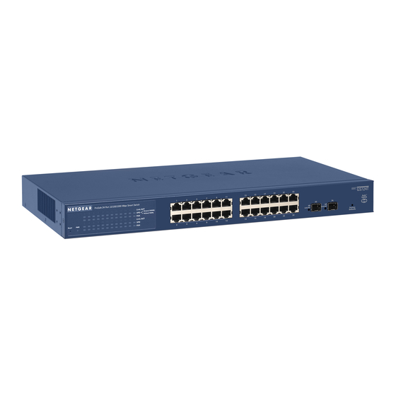
Front and Back Panel Configuration GS724TS Front and Back Panels The NETGEAR GS724TS Smart Switch is a 24-Port 10/100/1000 + 4-Port SFP Combo port switch, with each RJ45 ports capable of sensing the line speed and negotiating the operation duplex mode with the link partner automatically. -
Page 24: Gs748Ts Front And Back Panels
Two 19 pin HX stacking ports for full-duplex stacking linking. GS748TS Front and Back Panels The NETGEAR GS748TS Smart Switch is a 48-Port 10/100/1000 + 4-Port SFP Combo port smart stackable switch, with each RJ45 ports capable of sensing the line speed and negotiating the operation duplex mode with the link partner automatically. -
Page 25: Led Designations
Figure 3-2 illustrates the NETGEAR GS748TS Smart Switch back panel: Figure 3-4 The back panel contains the following: • A 100-240VAC/50-60 Hz universal input, which is a standard AC power receptacle for accommodating the supplied power cord. • Two 19 pin HX stacking ports for full-duplex stacking linking. -
Page 26: Port Leds
• Off - Switch acts as a slave member in a stack of switches. • Solid Green - Switch acts as a master unit in a stack of switches. The Stack Master LED is lit if there is an active stack link, and the unit is in stack mode. -
Page 27: Device Hardware Interfaces
Factory Defaults Button RJ-45 Ports RJ-45ports are auto-sensing ports. When inserting a cable into an RJ-45 port, the switch automatically ascertains the maximum speed (10 or 100 or 1000 Mbps) and duplex mode (half- or full-duplex) of the attached device. All ports support only Unshielded Twisted-Pair (UTP) cable terminated with an 8-pin RJ-45 plug. -
Page 28: Sfp Gbic Module
The GBIC module bays accommodate standard SFP GBIC modules, such as the AGM731F, AGM732F, or AGM733 from NETGEAR, allowing fiber connections on the network. The module bay is a combo port, sharing a connection with an RJ-45 port. Being a combo port, only one type of connection can be active at any given time. -
Page 29: Appendix A Troubleshooting
This chapter provides information about troubleshooting the NETGEAR Smart Switch. The topics include the following: • Troubleshooting Chart • Additional Troubleshooting Suggestions Troubleshooting Chart The following table lists symptoms, causes, and solutions of possible problems. Table A-1. Troubleshooting Chart Symptom Cause Power LED is off. -
Page 30: Additional Troubleshooting Suggestions
AC power from the switch and then reconnect AC source. If the problem continues, contact NETGEAR technical support. In North America, call 1-888-NETGEAR. If you are outside of North America, please refer to the support information card included with your product. -
Page 31: Auto-Negotiation
The RJ-45 ports negotiate the correct duplex mode and speed if the device at the other end of the link supports auto-negotiation. If the device does not support auto negotiation, the switch only determines the speed correctly and the duplex mode defaults to half-duplex. -
Page 32: Technical Specifications
Appendix B Technical Specifications Network Protocol and Standards Compatibility IEEE 802.3i 10Base-T IEEE 802.3u 100Base-TX,FX IEEE 802.3ab 1000Base-T IEEE 802.3z 1000Base-X IEEE 802.3x flow control IEEE 802.1x IEEE 802.1D Management IEEE 802.1Q Static VLAN (Up to 128 ranging from 2 to 4K) IEEE 802.1p Class of Service (CoS) Port-based QoS (options High/Normal) Port Trunking LACP... -
Page 33: Performance Specifications
Performance Specifications Forwarding modes: Store-and-forward Bandwidth: 68 Gbps (for GS724TS) / 116 Gbps (for GS748TS) Stacking Port Bandwidth: 20 Gbps Address database size: 4K media access control (MAC) addresses per system Mean Time Between Failure (MTBF): 167,355 hours for GS724TS, 125,566 hours for GS748TS Power Supply Power Consumption: 35.1W for GS724TS, 78.36W for GS748TS 100-240VAC/50-60 Hz universal input... -
Page 34: Electromagnetic Immunity
Electromagnetic Immunity EN 55022 (CISPR 22), Class A Safety CE mark, commercial UL listed (UL 1950) / CUL IEC950 / EN60950 Modules AGM731F 1000Base-SX SFP GBIC for multimode fiber AGM732F 1000Base-LX SFP GBIC for single mode fiber AGM733 1000Base-LZ GBIC for long haul single mode fiber Technical Specifications v1.0, November 2007... - Page 35 1U 1-3 8-pin 2-9 AC Power 2-6, 2-7 AGM731F 2-10 AGM732F 2-10 AGM733 2-10 Applying AC Power 4-17 Attaching Switch to a Rack 4-15 Auto Sensing 1-2 Auto Uplink 2-9, 2-10 Auto-negotiating 1-3 Auto-sensing 2-9 Back-pressure 1-3 Brackets 4-14 Category 5 Unshielded Twisted-Pair 1-2...
- Page 36 Rubber footpads 1-4 SFP GBIC Module 2-10 SFP Link/ACT LED 2-8 SFP Module Bay 4-17 Site Requirements 4-13 Small Form-factor Pluggable (SFP) 1-2 Smart Switch Resource CD 1-4 SmartWizard Discovery 1-2 Straight-through 2-9 Support Information Card 1-4 System LEDs 2-9 Temperature 4-14...
- Page 37 User’s Manual 1-4 UTP 4-16 Ventilation 4-14 VLAN 1-1 Warranty 1-4 Web-based Graphical User Interface 1-1 Index-3 v1.0, November 2007...
- Page 38 Index-4 v1.0, November 2007...