FujiFilm FinePix S6000fd Service Manual
Hide thumbs
Also See for FinePix S6000fd:
- Specifications (2 pages) ,
- Quick start (2 pages) ,
- Owner's manual (196 pages)
Table of Contents
Advertisement
BECAUSE THIS PRODUCTIS RoHS LEAD-FREE COMPLIANT, USE THE DESIG-
NATED AFTER-SELES PARTS AND THE DESIGNATED LEAD-FREE SOLDER WHEN
PERFORMING REPAIRS. (Refer to page 3 to page 5)
THE COMPONENTS IDENTIFIED WITH THE MARK "
DIAGRAM AND IN THE PARTS LIST ARE CRITICAL FOR SAFETY.
PLEASE REPLACE ONLY WITH THE COMPONENTS SPECIFIED ON THE SCHEMATIC
DIAGRAM AND IN THE PARTS LIST.
IF YOU USE PARTS NOT SPECIFIED, IT MAY RESULT IN A FIRE AND AN
ELECTRICAL SHOCK.
FUJI PHOTO FILM CO., LTD.
FinePix S6000fd/
CAUTION
WARNING
DIGITAL CAMERA
SERVICE MANUAL
US/EU/EG/EE/AS/CH/JP-Model
" ON THE SCHEMATIC
S6500fd
Ref.No.:ZM00647-100
Printed in Japan 2006.09
Advertisement
Table of Contents

Related Manuals for FujiFilm FinePix S6000fd


Summary of Contents for FujiFilm FinePix S6000fd
-
Page 1: Digital Camera
DIGITAL CAMERA FinePix S6000fd/ S6500fd SERVICE MANUAL US/EU/EG/EE/AS/CH/JP-Model CAUTION BECAUSE THIS PRODUCTIS RoHS LEAD-FREE COMPLIANT, USE THE DESIG- NATED AFTER-SELES PARTS AND THE DESIGNATED LEAD-FREE SOLDER WHEN PERFORMING REPAIRS. (Refer to page 3 to page 5) WARNING THE COMPONENTS IDENTIFIED WITH THE MARK “... - Page 2 FinePix S6000fd/S6500fd Service Manual SAFETY CHECK-OUT After correcting the original problem, perform the following safety check before return the product to the customer. 1. Check the area of your repair for unsoldered or poorly CAUTION: FOR CONTINUED soldered connections. Check the entire board surface PROTECTION AGAINST FIRE for solder splasher and bridges.
- Page 3 FinePix S6000fd/S6500fd Service Manual RoHS lead-free compliance Because this product is RoHS lead-free compliant, use the designated after-sales parts and the designated lead-free solder when performing repairs. <Background & Overview> With the exception of parts and materials expressly excluded from the RoHS directive (*1), all the internal connections and component parts and materials used in this product are lead-free compliant (*2) under the European RoHS directive.
- Page 4 FinePix S6000fd/S6500fd Service Manual Setting temperature during lead-free soldering • Lead-free solder melting temperature The melting point of eutectic (Sn-Pb) solder is 183°C, while the melting point of lead-free solder (Sn-Ag-Cu) is 30°C higher at 220°C. • Soldering iron tip temperature The temperature setting for the soldering iron used should be such that the tip of the soldering iron is at the correct bonding temperature for the connection.
- Page 5 FinePix S6000fd/S6500fd Service Manual Solder wire (thread) Use the lead-free solders specified below. Solder type: Sn96.5Ag3Cu0.5 (Displayed symbol: SnAgCu) Wire diameter: 0.6, 0.8 or 1.0 mm Sample: lead-free Wire diameter 0.8mm Solder type (Displayed symbol) SnAgCu Flux Conventional flux can be used.
-
Page 6: Table Of Contents
CONTENTS FinePix S6000fd/S6500fd Service Manual CONTENTS 1. General ............1-1 3-6. Circuit Diagrams ..........3-5 3-6-1. AV BLOCK ..........3-5 1-1. Product specification .......... 1-1 3-6-2. CAMERA BLOCK ........3-6 1-2. Explanation of Terms .......... 1-4 3-6-3. DCDC BLOCK ........3-7 1-3. - Page 7 CONTENTS FinePix S6000fd/S6500fd Service Manual CONTENTS 4. Adjustments ..........4-1 6. Parts List ............6-1 4-1. Important point before Adjustment ..... 4-1 6-1. Packing and Accessories ........6-1 4-1-1. The handling of image files in internal 6-1-1. US-model ..........6-1 memory ..........
- Page 8 FinePix S6000fd/S6500fd Service Manual MEMO...
-
Page 9: General
FinePix S6000fd/S6500fd Service Manual 1. General 1-1. Product specification System Model Digital camera FinePix S6000fd / FinePix S6500fd Effective pixels 6.3 million pixels 1/1.7-inch Super CCD HR Storage media Internal memory (approx. 10 MB)/xD-Picture Card (16/32/64/128/256/512 MB/1 GB/2 GB) File format Still image: DCF-compliant Compressed: Exif ver.2.2 JPEG, DPOF-compatible... - Page 10 1. General FinePix S6000fd/S6500fd Service Manual System Focus Mode: Single-AF, Continuous AF, Manual focus/One-touch AF (when using Manual focus) AF system: TTL contrast-type, AF-assist illuminator AF frame selection: AF (CENTER), AF (MULTI), AF(AREA) White balance Automatic scene recognition/Preset (Fine, Shade, Fluorescent (Daylight),...
- Page 11 1. General FinePix S6000fd/S6500fd Service Manual Input/Output Terminal A/V OUT NTSC/PAL-type (with monaural sound) (Audio/Visual output) Digital input/output USB 2.0 High-Speed/PTP (Picture Transfer Protocol) DC input socket AC Power Adapter AC-5VX (sold separately) Power Supply and Others Power supply Use one of the following: •...
-
Page 12: Explanation Of Terms
1. General FinePix S6000fd/S6500fd Service Manual 1-2. Explanation of Terms Deactivated batteries: Leaving an Ni-MH battery unused in storage for a long period may cause a rise in the level of substances that inhibit current flow inside the battery and result in a dormant battery. -
Page 13: Names Of External Components
1. General FinePix S6000fd/S6500fd Service Manual 1-3. Names of External Components Zoom ring Power switch Focus ring Shutter button Exposure compensation button Continuous shooting button Mode dial Microphone Flash Focus mode selector switch (One-touch AF) button Strap mount AF-assist illuminator... - Page 14 1. General FinePix S6000fd/S6500fd Service Manual Diopter adjustment dial Viewfinder (EVF) Intelligent Face Detection button EVF/LCD (monitor selector) button Digital zoom button Indicator lamp 4-direction ( ) button LCD monitor MENU/OK button DISP (Display)/ Photo mode ( ) button BACK button...
-
Page 15: Disassembly
2. Disassembly FinePix S6000fd/S6500fd Service Manual 2. Disassembly 2-1. Names of internal Components MSW PWB ASSY R CASE ASSY KSW PWB ASSY FRAME LCD LCD CONST REINFORCEMENT LCD FLASH CONST RSW PWB ASSY MAIN PWB ASSY EVF UNIT CONST ASSY HOLDER BATTRY... -
Page 16: Removing The Rear Const
2. Disassembly FinePix S6000fd/S6500fd Service Manual 2-2. Removing the REAR CONST (1) Remove the 2 screws (M1.7 x 9.0). (2) Remove the 3 screws (M1.7 x 3.5). (3) Apply pressure in the direction of the arrow to disengage the catch for section A. - Page 17 2. Disassembly FinePix S6000fd/S6500fd Service Manual (5) Unlock the connector and remove the LCD FPC. (6) Unlock the connector and remove the MAIN-KSW FPC. [Notes on Assembly] Fit the REAR CONST into the F CASE with the CARD COVER open (to prevent damage to SW551).
-
Page 18: Disassembling The Rear Const
2. Disassembly FinePix S6000fd/S6500fd Service Manual 2-3. Disassembling the REAR CONST (1) Remove the 4 screws (M1.7 x 4.0). (2) Remove the 4 screws (M1.7 x 4.0B). (3) Remove the LCD FRAME. (4) Unlock connector CN802 and remove the KSW-MSW FFC. -
Page 19: Removing The Main Pwb Assy And Flash Pwb Assy
2. Disassembly FinePix S6000fd/S6500fd Service Manual 2-4. Removing the MAIN PWB ASSY and FLASH PWB ASSY (1) Remove the 2 wire harnesses in the direction of the arrow. (2) Remove the 2 FPCs in the direction of the arrow. (3) Remove the 2 FFCs in the direction of the arrow. - Page 20 2. Disassembly FinePix S6000fd/S6500fd Service Manual (9) Peel off the TAPE CONDENSER. (10) Discharge the main capacitor. Take care not to touch the main capacitor terminals before discharging the capacitor. (11) Push the connector catch upwards. (12) Remove the connector (FLASH CONST) in the direction of the arrow.
-
Page 21: Removing The Holder Battery
2. Disassembly FinePix S6000fd/S6500fd Service Manual 2-5. Removing the HOLDER BATTERY (1) Remove the screw (M1.7 x 9.0). (2) Remove the HOLDER BATTERY in the direction of the arrow. [Notes on Assembly] During HOLDER BATTERY assembly, set the RELEASE LEVER to OFF (to prevent damage to SW902 and SW903). -
Page 22: Removing The Lens Assy
2. Disassembly FinePix S6000fd/S6500fd Service Manual 2-6. Removing the LENS ASSY (1) Remove the 2 screws (M1.7 x 4.0). (2) Remove the MAIN FRAME in the direction of the arrow. (3) Remove the 4 screws (M2.0 x 10.0). (4) Remove the LENS ASSY in the direction of the arrow. -
Page 23: Removing The Lens Holder
2. Disassembly FinePix S6000fd/S6500fd Service Manual 2-7. Removing the LENS HOLDER (1) Remove the wire harness (SPEAKER). (2) Remove the 4 screws (M2.0 x 9.0). (3) Remove the LENS HOLDER in the direction of the arrow. (4) Remove the wire harness (MIC). - Page 24 2. Disassembly FinePix S6000fd/S6500fd Service Manual [Notes on Assembly] • Arrange the MIC wire harness as shown in the figure on the right. • Arrange the SPEAKER wire harness as shown in the figure on the right. • Assemble with the focus mode selector switch set to the "S"...
-
Page 25: Removing The Flash Const
2. Disassembly FinePix S6000fd/S6500fd Service Manual 2-8. Removing the FLASH CONST (1) Remove the 2 screws (M1.7 x 4.0). (2) Remove the FLASH CONST in the direction of the arrow. [Assembly] Assemble by performing the disassembly procedure in reverse. 2-9. -
Page 26: Specifications For The Sheet Component Attachment Locations
2. Disassembly FinePix S6000fd/S6500fd Service Manual 2-10. Specifications for the sheet component attachment locations 2-10-1. Affixing the REINFORCEMENT LCD (1) Attach the LCD FRAME TAPE to the LCD FRAME as shown in the figure on the right. (2) Align the LCD FRAME bosses and attach the REINFORCEMENT LCD. -
Page 27: Affixing The Mf Sheet
2. Disassembly FinePix S6000fd/S6500fd Service Manual 2-10-2. Affixing the MF SHEET (1) Attach the MF SHEET to the MAIN FRAME as shown in the figure on the right. (2) Stick the UL TAPE around the central section of the MF SHEET, ensuring that the MF SHEET and the EMI SHEET CCD on the CCD FPC are not touching. - Page 28 2. Disassembly FinePix S6000fd/S6500fd Service Manual MEMO 2-14...
-
Page 29: Schematics
3. Schematics FinePix S6000fd/S6500fd Service Manual 3. Schematics 3-1. Cautions <Cautions when replacing parts> • Do not reuse removed parts. Always use new parts. • Note that the negative side of tantalum condensers is readily damaged by heat. • Except for chemical condensers and tantalum condensers, voltage is not displayed on condensers with a voltage resistance of 50V or less. -
Page 30: Description Of Main Block Functions
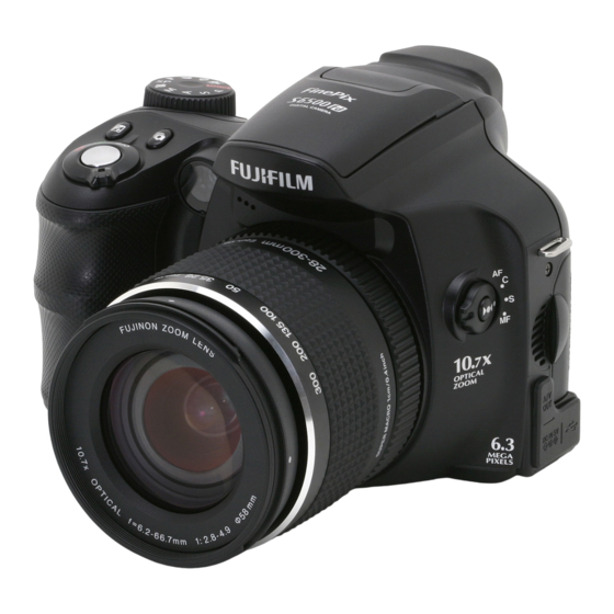
The 10.7x zoom lens provided on the FinePix S6000fd uses high-definition Fujinon optics and an ultra-wide 28-300 mm focal range, so you can use just one lens for almost any type of shot. At 28 mm it is perfect for landscapes and snapshots while the 300 mm focal length is ideal for sporting events, concerts and portraits. -
Page 31: Block Diagram
3. Schematics FinePix S6000fd/S6500fd Service Manual 3-4. Block Diagram MAIN PWB IC201 LED Dr TK11880F-G MC-10036F1 AF ASSIST LED IC501 IC102 o l l IC452 LC15009A IC951 ØV ØH IC451 Motor Drv. R2A30404NP i n i IC151 IC651 AV_DET FLASH... -
Page 32: Overall Connection Diagram
3. Schematics FinePix S6000fd/S6500fd Service Manual 3-5. Overall connection Diagram AF LED EVF FPC 1 2 3 4 5 6 7 8 8 7 6 5 4 3 2 1 FGB165-0061 6FHJ-SM1-GB-TBLFSN AF LED BLK SPEAKER- MIC_UNIT PLUMGER_UNIT 1 2 3 4 5 6 7 8 9... -
Page 33: Circuit Diagrams
3. Schematics FinePix S6000fd/S6500fd Service Manual 3-6. Circuit Diagrams 3-6-1. AV BLOCK... -
Page 34: Camera Block
3. Schematics FinePix S6000fd/S6500fd Service Manual 3-6-2. CAMERA BLOCK... -
Page 35: Dcdc Block
3. Schematics FinePix S6000fd/S6500fd Service Manual 3-6-3. DCDC BLOCK... -
Page 36: Evf Block
3. Schematics FinePix S6000fd/S6500fd Service Manual 3-6-4. EVF BLOCK... -
Page 37: Fdi Block
3. Schematics FinePix S6000fd/S6500fd Service Manual 3-6-5. FDI BLOCK... -
Page 38: Flash Jack Block
3. Schematics FinePix S6000fd/S6500fd Service Manual 3-6-6. FLASH JACK BLOCK 3-10... -
Page 39: Key Block
3. Schematics FinePix S6000fd/S6500fd Service Manual 3-6-7. KEY BLOCK 3-11... -
Page 40: Ksw Block
3. Schematics FinePix S6000fd/S6500fd Service Manual 3-6-8. KSW BLOCK 3-12... -
Page 41: Lcd Block
3. Schematics FinePix S6000fd/S6500fd Service Manual 3-6-9. LCD BLOCK 3-13... -
Page 42: Motor Block
3. Schematics FinePix S6000fd/S6500fd Service Manual 3-6-10. MOTOR BLOCK 3-14... -
Page 43: Pman Block
3. Schematics FinePix S6000fd/S6500fd Service Manual 3-6-11. PMAN BLOCK 3-15... -
Page 44: Process Block (Io)
3. Schematics FinePix S6000fd/S6500fd Service Manual 3-6-12. PROCESS BLOCK (IO) 3-16... -
Page 45: 3-6-.13 Process Block (Pw)
3. Schematics FinePix S6000fd/S6500fd Service Manual 3-6-.13 PROCESS BLOCK (PW) 3-17... -
Page 46: Process Block (Sys)
3. Schematics FinePix S6000fd/S6500fd Service Manual 3-6-14. PROCESS BLOCK (SYS) 3-18... -
Page 47: Af Led Block
3. Schematics FinePix S6000fd/S6500fd Service Manual 3-6-15. AF LED BLOCK 3-6-16. CCD FPC BLOCK 3-19... -
Page 48: Cn Block
3. Schematics FinePix S6000fd/S6500fd Service Manual 3-6-17. CN BLOCK 3-6-18. FSW BLOCK 3-20... -
Page 49: Emi Block
3. Schematics FinePix S6000fd/S6500fd Service Manual 3-6-19. EMI BLOCK 3-21... -
Page 50: Lcd Data 7 Block
3. Schematics FinePix S6000fd/S6500fd Service Manual 3-6-20. LCD DATA 7 BLOCK 3-22... -
Page 51: Media Block
3. Schematics FinePix S6000fd/S6500fd Service Manual 3-6-21. MEDIA BLOCK 3-6-22. MSW BLOCK 3-23... -
Page 52: Plunger Block
3. Schematics FinePix S6000fd/S6500fd Service Manual 3-6-23. PLUNGER BLOCK 3-6-24. USB BLOCK 3-24... -
Page 53: Rsw Block
3. Schematics FinePix S6000fd/S6500fd Service Manual 3-6-25. RSW BLOCK 3-6-26. XE BLOCK 3-25... -
Page 54: Ssw Block
3. Schematics FinePix S6000fd/S6500fd Service Manual 3-6-27. SSW BLOCK 3-26... -
Page 55: Mounted Parts Diagrams
3. Schematics FinePix S6000fd/S6500fd Service Manual 3-7. Mounted Parts Diagrams 3-7-1. FSW PWB ASSY 3-27... -
Page 56: Ksw Pwb Assy
3. Schematics FinePix S6000fd/S6500fd Service Manual 3-7-2. KSW PWB ASSY 3-28... -
Page 57: Msw Pwb Assy
3. Schematics FinePix S6000fd/S6500fd Service Manual 3-7-3. MSW PWB ASSY 3-29... -
Page 58: Rsw Pwb Assy
3. Schematics FinePix S6000fd/S6500fd Service Manual 3-7-4. RSW PWB ASSY 3-30... -
Page 59: Ssw Pwb Assy
3. Schematics FinePix S6000fd/S6500fd Service Manual 3-7-5. SSW PWB ASSY 3-31... -
Page 60: Xe Pwb Assy
3. Schematics FinePix S6000fd/S6500fd Service Manual 3-7-6. XE PWB ASSY 3-32... -
Page 61: Flash Pwb Assy
3. Schematics FinePix S6000fd/S6500fd Service Manual 3-7-7. FLASH PWB ASSY 3-33... -
Page 62: Main Pwb Assy
3. Schematics FinePix S6000fd/S6500fd Service Manual 3-7-8. MAIN PWB ASSY 3-34... -
Page 63: Adjustments
4. Adjustments FinePix S6000fd/S6500fd Service Manual 4. Adjustments 4-1. Important point before Adjustment 4-1-1. The handling of image files in internal memory This camera has internal memory, image files stored in the internal memory should be handled as described below when the camera is replaced or repaired. -
Page 64: Important Point Adjustment When Replacing Major Parts
4. Adjustments FinePix S6000fd/S6500fd Service Manual 4-1-2. Important point Adjustment when Replacing Major Parts Adjust the item shown by ¡ in the table below at the part replacement of LENS ASSY, MAIN PWB, FLASH ASSY and LCD CONST. (Other part replacements need not be adjusted.) -
Page 65: Use Jig List
LCD adjustment Common with the FinePix S304 *1: Please downloaded from Web server (http://fujifilm-di.intranets.com/). *2: Select one the power cable suitable each country. *3: S9000/9500 Zoom drive jig is a Jig by which the thing that the zoom position match of the shading compensation adjustment automatically does becomes possible. -
Page 66: Adjustment Software Installation
4. Adjustments FinePix S6000fd/S6500fd Service Manual 4-5. Adjustment software installation 4-5-1. Various downloading software decompressions, preservation methods, and notes The PC adjustment softwares are in a specified Web server, and both of these are the compression of ZIP form files. -
Page 67: Installation Of Dsc Jig Driver
4. Adjustments FinePix S6000fd/S6500fd Service Manual 4-5-2. Installation of DSC jig driver * Since this camera uses the USB for communications with the personal computer, in order to start the PC adjustment software, [the DSC jig driver] needs to be installed in the personal computer beforehand. -
Page 68: Initial Settings Of The Adjustment Software
4. Adjustments FinePix S6000fd/S6500fd Service Manual 4-6. Initial Settings of the Adjustment Software * The initial settings are already written in the "FFW.ini" file, therefore perform the following procedure to the letter. Note that, if you change file names, the software will not start up. - Page 69 4. Adjustments FinePix S6000fd/S6500fd Service Manual <Step 3> Select the "EVR&Comm." tab ([1] in Fig. 4-6-3) in the "Customize" dialog box that appears. Set the "EVR&Comm." items as follows. Item Details etc (-V2) Check LANC page Check <Fig. 4-6-3> <Step 4>...
- Page 70 4. Adjustments FinePix S6000fd/S6500fd Service Manual [ Setting when S9000/9500 Zoom drive jig is used ] Always use this jig for AF adjustment. But it can be used for either manual or automatic adjustment for shading. A zoom drive jig is not required for manual adjustment.
-
Page 71: Starting The Adjustment Software
4. Adjustments FinePix S6000fd/S6500fd Service Manual 4-7. Starting the Adjustment Software <Step 1> Double-click on [FFW.EXE] (Fig. 4-5-3) in the folder copied to the C drive (see ‘4-5-1. Various downloading software decompressions, preservation methods and notes’) to display the adjustment software start-up screen. - Page 72 4. Adjustments FinePix S6000fd/S6500fd Service Manual <Step 4> FinePix S6000fd_S6500fd Jig Mode Setup Screen 1. Set the Jig mode by using [Power cable jig (5V)]. 1) Set the mode to the [AUTO] mode. 2) Set the focus mode to the [S-AF].
- Page 73 4. Adjustments FinePix S6000fd/S6500fd Service Manual <Step 6> FinePix S6000fd_6500fd_W adjustment item select screen 0. [ R ] : Flash memory reset *Only use for when the MAIN PWB has been replaced. 1. [ F 4 ] : CCD Defect Correction / OFD Adjustment 2.
-
Page 74: R] : Flash Memory Reset
4. Adjustments FinePix S6000fd/S6500fd Service Manual 4-8. [R] : Flash Memory Reset <Note> Only reset the flash memory when the MAIN PWB ASSY has been replaced. When the MAIN PWB ASSY has been replaced, always reset the flash memory before making any other adjustments. - Page 75 4. Adjustments FinePix S6000fd/S6500fd Service Manual <Step 2> Flash memory reset (EVR) AND Internal Memory Format < Attention > When the MAIN PWB ASSY has been replaced, always reset the flash memory before making any other adjustments. Only reset the flash memory when the MAIN PWB ASSY has been replaced.
-
Page 76: F4] : Ccd Defect Correction / Ofd Adjustment
4. Adjustments FinePix S6000fd/S6500fd Service Manual 4-9. [F4] : CCD Defect Correction / OFD Adjustment CCD data input is required when the LENS ASSY or MAIN PWB ASSY is replaced. [Method of acquiring CCD data] 1. When you exchange LENS ASSY -->... - Page 77 4. Adjustments FinePix S6000fd/S6500fd Service Manual < Use the pattern box for Camera adjustment > Turn on the power supply in the pattern box. Afterwards, wait for about ten minutes so that the source of light may stabilize. Pattern BOX...
- Page 78 4. Adjustments FinePix S6000fd/S6500fd Service Manual <Step 3> 610W0052 CCD Defect Correction / OFD Adjustment < Preparations > (1) Enter the 8-digit ccdserial number in the CCD Data Input dialog box. The file extrension need not be entered. (2) Insert the floppy disk in the A: drive (floppy disk drive) on the PC.
- Page 79 4. Adjustments FinePix S6000fd/S6500fd Service Manual <Step 4> CCD Defect Correction / OFD adjustment is completed. Press the [Enter] key to return to the Adjustment Item Selection Screen. <Fig. 4-9-5> 4-17...
-
Page 80: F5] : Camera Adjustment
4. Adjustments FinePix S6000fd/S6500fd Service Manual 4-10. [F5] : Camera Adjustment (shutter adjustment, adjustment for reduced aperture sensitivity, ISO sensitivity adjustment, white balance adjustment, AE adjustment, offset level adjustment) < Setup for Camera Adjustment> < Importance! > 1. Calibrate the pattern box before adjusting the camera. - Page 81 4. Adjustments FinePix S6000fd/S6500fd Service Manual <Step 1> Select [F5] Camera Adjustment on the [Adjustment Items Select] screen. --> The [Camera Adjustment Preparation] screen appears. <Step 2> Run the adjustment in accordance with the instructions on the screen. Camera Adjustment <...
- Page 82 4. Adjustments FinePix S6000fd/S6500fd Service Manual <Step 4> Squeezing sensitivity decreasing rate adjustment (1) Set the distance between the camera and pattern box. (2) Place the LB140 filter in front of the lens. When preparations are complete, press the [Enter] key.
- Page 83 4. Adjustments FinePix S6000fd/S6500fd Service Manual <Step 6> WB adjustment with filter (1) Set the distance between the camera and pattern box. (2) Place the LB140 filter in front of the lens. When preparations are complete, press the [Enter] key.
- Page 84 4. Adjustments FinePix S6000fd/S6500fd Service Manual <Step 8> WB adjustment with filter (high sensitivity) (1) Set the distance between the camera and pattern box. (2) Place the LB140 filter in front of the lens. When preparations are complete, press the [Enter] key.
- Page 85 4. Adjustments FinePix S6000fd/S6500fd Service Manual <Step 10> Transfer efficiency adjustment (1) Set the distance between the camera and pattern box. (2) Place the LB140 filter in front of the lens. When preparations are complete, press the [Enter] key. LB140 filter ------------------------------ 30mm or less.
-
Page 86: S ]: Shading Compensation Adjustment
4. Adjustments FinePix S6000fd/S6500fd Service Manual 4-11. [ S ]: Shading compensation adjustment (Shading compensation adjustment) < Setup for Shading compensation adjustment > < Importance! > 1. Calibrate the pattern box before adjusting the shading. 2. Ensure that shading adjustment is carried out in dark surroundings (ideally in a darkroom environment). - Page 87 4. Adjustments FinePix S6000fd/S6500fd Service Manual <Step 2> Set the zoom position in Zoom position Darken the surrounding, and press enter key of PC. <Fig. 4-11-2> --> The [Zoom setting of [12] position] screen appears. <Step 3> Set the zoom position in...
- Page 88 4. Adjustments FinePix S6000fd/S6500fd Service Manual <Step 4> Set the zoom position in Zoom position Out of alignment to the zoom position <Fig. 4-11-4> --> The [Zoom setting of [27] position] screen appears. <Step 5> Set the zoom position in...
- Page 89 4. Adjustments FinePix S6000fd/S6500fd Service Manual <Step 6> Set the zoom position in Zoom position Out of alignment to the zoom position <Fig. 4-11-6> --> The [Zoom setting of [1] position] screen appears. <Step 7> Set the zoom position in...
- Page 90 4. Adjustments FinePix S6000fd/S6500fd Service Manual <Step 8> Set the zoom position in Zoom position Out of alignment to the zoom position <Fig. 4-11-8> --> Write the adjustment data to the flash ROM when adjustment has been completed correctly. --> The [Shading compensation adjustment Complete] screen appears.
-
Page 91: F6] : Af Adjustment
4. Adjustments FinePix S6000fd/S6500fd Service Manual 4-12. [F6] : AF Adjustment <Setup for AF Adjustment> (1) Set the camera in the zoom drive jig. (2) Set up the camera so that the distance from the multi-stripe chart to the front edge of the camera's filter ring is 897.3±1 (3) Illuminate the AF chart with a light source. - Page 92 4. Adjustments FinePix S6000fd/S6500fd Service Manual <Step 2> Run the adjustment in accordance with the instructions on the screen. <Note> Always use a 800mm conversion lens. AF Adjustment < AF Adjustment Preparations > (1) Prepare a 800mm conversion lens. (2) Prepare a S9100/S9600 Multi-stripe chart.
- Page 93 4. Adjustments FinePix S6000fd/S6500fd Service Manual <Step 4> AF Adjustment (900mm) (1) Remove the conversion lens. (2) Adjust the position of the camera so that the center of the S9100/S9600 Multi-stripe chart is displayed in the camera LCD. When preparations (1) - (2) are complete, press the [Enter] key.
-
Page 94: F7] : Flash Adjustment
4. Adjustments FinePix S6000fd/S6500fd Service Manual 4-13. [F7] : Flash Adjustment <Setup for Flash Adjustment> (1) As flash adjustment is readily affected by external light, ensure that the vicinity of the gray chart is very dark. (2) Ensure that distance is measured from the front of the camera during flash adjustment. - Page 95 4. Adjustments FinePix S6000fd/S6500fd Service Manual <Step 3> Flash Adjustment (1) Adjust brightness so that the periphery of the gray chart is as dark as possible. (2) Adjust the camera so that the entire chart is shown on the LCD monitor.
-
Page 96: F1] : Battery Voltage Adjustment
4. Adjustments FinePix S6000fd/S6500fd Service Manual 4-14. [F1] : Battery Voltage Adjustment <Setup for Battery Voltterge Adjustment> (1) When adjusting the battery voltage, supply power (5.0V) to the camera from the [Power Cable Jig] before setting the jig mode. (2) Always measure input voltage in the vicinity of the DC IN terminal. - Page 97 4. Adjustments FinePix S6000fd/S6500fd Service Manual <Step 2> Run the adjustment in accordance with the instructions on the screen. Battery Voltage Adjustment (IPS2) <Preparations> 1. Check that the Power Cable Jig and the camera are connected. *If not, return to the Jig Mode Setup screen, and connect the Power Cable Jig and the camera.
- Page 98 4. Adjustments FinePix S6000fd/S6500fd Service Manual <Step 4> Battery Voltage Adjustment (IPS2) (1) Supply 4.40V (+0.02V/-0.00V). When preparations are complete, press the [Enter] key. Result= (2) Supply 4.00V (+0.02V/-0.00V). When preparations are complete, press the [Enter] key. <Fig. 4-14-3> —> The [7.20V Input] screen appears.
- Page 99 4. Adjustments FinePix S6000fd/S6500fd Service Manual <Step 6> Battery Voltage Adjustment (IPS2) (1) Supply 4.40V (+0.02V/-0.00V). When preparations are complete, press the [Enter] key. Result= (2) Supply 4.00V (+0.02V/-0.00V). When preparations are complete, press the [Enter] key. Result= (3) Supply 7.20V (+0.02V/-0.00V).
-
Page 100: F2] : Mode Dial Adjustment
4. Adjustments FinePix S6000fd/S6500fd Service Manual 4-15. [F2] : Mode Dial Adjustment <Setup for Mode Dial Adjustment> (1) When adjusting the Mode Dial, supply power (5.0V) to the camera from the [Power Cable Jig] before setting the jig mode. (2) Always measure input voltage in the vicinity of the DC IN terminal. - Page 101 4. Adjustments FinePix S6000fd/S6500fd Service Manual <Step 2> Mode Dial Adjustment (1) Set the mode dial to [AUTO]. (2) Please input 5.00+-0.01V from DC-IN Jack. Press the [Enter] key of PC after setting the camera. Press [1] key to PC when not proceeding to the next step.
-
Page 102: F11] : Video Adjustment
4. Adjustments FinePix S6000fd/S6500fd Service Manual 4-16. [F11] : Video Adjustment <Setup for Video Adjustment> (1) Set up the PCI-2746C board in the computer as explained in the instructions for the video adjustment jig. (2) If the waveform of the brightness signal (Y) or color signal (C) does not appear in the “WAVE No. 0” window during adjustments, check the connections of the video adjustment jig. - Page 103 4. Adjustments FinePix S6000fd/S6500fd Service Manual <Step 2> Run the adjustment in accordance with the instructions on the screen. Video Adjustment < Video Adjustment Preparations > (1) Connect the camera and video adj. jig with the video cable. (2) Confirm Video jig is connected with the video cable.
-
Page 104: F3] : Lcd Adjustment
4. Adjustments FinePix S6000fd/S6500fd Service Manual 4-17. [F3] : LCD Adjustment <Setup for LCD Adjustment> (Set up the PCI-2747C board in the computer as explained in the instructions for the LCD adjustment Jig. PC for adjustments and checks Fine Pix S6000fd/S6500fd... - Page 105 4. Adjustments FinePix S6000fd/S6500fd Service Manual <Step 3> LCD Adjustment < LCD Adjustment Preparations > (1) Check that the LCD adjustment xD-Picture card has been inserted in the camera. (2) Attach the sensor of the LCD adjustment jig to the center of the LCD monitor.
-
Page 106: F8] : Firmware Download
4. Adjustments FinePix S6000fd/S6500fd Service Manual 4-18. [F8] : Firmware Download Attention : When the download of the firmware is needed, FUJI SERVICE BULLETIN is contacted from FTYO/QA. Till then, disregard this item. <Setup for Firmware Download> FinePix S6000fd/S6500fd PC for adjustment and checks... - Page 107 4. Adjustments FinePix S6000fd/S6500fd Service Manual <Step 2> Firmware download is completed (1) Remove the DC Jack cable from the camera. (2) Turn off power lever switch. (3) Reconnect DC Jack cable. (4) Switch camera power ON while pressing the shutter button.
-
Page 108: F12] : End Setting
3. USB ID write details 1) USB ID write requires that the USB device (in this case FinePix S6000fd/S6500fd) be unique throughout the world. For this reason, each device has a unique ID as determined by the USB standard. If multiple devices with the same USB ID are connected to a single PC, the PC will be unable to identify each USB device, thus preventing operation. - Page 109 4. Adjustments FinePix S6000fd/S6500fd Service Manual <Step 1> Select [F12] End Setting on the [Adjustment Items Select] screen. —> The [End Setting Description] screen appears. <Step 2> Run the adjustment in accordance with the instructions on the screen. End Setting...
- Page 110 4. Adjustments FinePix S6000fd/S6500fd Service Manual <Step 4> Destination setting The destination is selected from an undermentioned list, according to third character from left side of the serial number. The third character <A> FinePix S6000fd J-model 0 to 9 <B> FinePix S6000fd US-model A to H,J,K <C>...
- Page 111 4. Adjustments FinePix S6000fd/S6500fd Service Manual <Step 6> USB ID Selected U.S.A.. Press the [Enter] key! <Fig. 4-19-5> —> The [FinePix S6000fd_6500fd Adjustment End] screen appears. <Step 7> FinePix S6000fd_6500fd Adjustment is completed. 1) Remove USB cable from the camera.
- Page 112 4. Adjustments FinePix S6000fd/S6500fd Service Manual MEMO 4-50...
-
Page 113: Inspection
5. Inspection FinePix S6000fd/S6500fd Service Manual 5. Inspection 5-1. Required Measuring Equipment Measuring equipment Remarks Power supply AC adapter (AC-5V), Regurated power supply Digital voltmeter For general use Ammeter For general use (able to measure 1mA or less) Power Cable Jig... -
Page 114: Inspection And Factory Settings
5. Inspection FinePix S6000fd/S6500fd Service Manual 5-3. Inspection and Factory Settings Sequemnce Item Mode Preparations for adjustment Method of adjustment Measuring Measurement points (measurement points, subject, other) (VRs, waveforms, required values) equipment and jigs (VRs, positions) External visual (1) Observe the camera. - Page 115 5. Inspection FinePix S6000fd/S6500fd Service Manual Sequemnce Item Mode Preparations for adjustment Method of adjustment Measuring Measurement points (measurement points, subject, other) (VRs, waveforms, required values) equipment and jigs (VRs, positions) Resolution check Auto mode (1) Use a macro resolution...
- Page 116 5. Inspection FinePix S6000fd/S6500fd Service Manual Sequemnce Item Mode Preparations for adjustment Method of adjustment Measuring Measurement points (measurement points, subject, other) (VRs, waveforms, required values) equipment and jigs (VRs, positions) Playback check Playback (1) Plug the AV cable into the (1) Check that the LCD image camera.
- Page 117 5. Inspection FinePix S6000fd/S6500fd Service Manual Sequemnce Item Mode Preparations for adjustment Method of adjustment Measuring Measurement points (measurement points, subject, other) (VRs, waveforms, required values) equipment and jigs (VRs, positions) Initialization (1) Set Macro mode to the (1) 4-way button (left) default setting.
- Page 118 5. Inspection FinePix S6000fd/S6500fd Service Manual Sequemnce Item Mode Preparations for adjustment Method of adjustment Measuring Measurement points (measurement points, subject, other) (VRs, waveforms, required values) equipment and jigs (VRs, positions) Factory setting (1) Mode dial (1) AUTO (2) Flash...
-
Page 119: Parts List
6. Parts List FinePix S6000fd/S6500fd Service Manual 6. Parts List 6-1. Packing and Accessories 6-1-1. US-model A104 A113 A112 A111 A106 A120 A108 A107 A119 A102 A118 A117 A110 A116 A105 A114 A115 A103 A101 A109 Ref No. Parts No. -
Page 120: Jp-Model
6. Parts List FinePix S6000fd/S6500fd Service Manual 6-1-2. JP-model A104 A113 A112 A111 A107 A106 A108 A117 A102 A110 A115 A116 A105 A114 A103 A101 A118 A109 Ref No. Parts No. Description Comment A101 FZ06668-100 UNITARY BOX A102 FZ06670-100 SHEET MOLD T... -
Page 121: Eu-Model
6. Parts List FinePix S6000fd/S6500fd Service Manual 6-1-3. EU-model A104 A113 A112 A111 A116 A125 A106 A108 A124 A123 A107 A122 A121 A102 A120 A119 A110 A118 A105 A114 A115 A103 A101 A109 A117 N.S.=Not Supply Ref No. Parts No. -
Page 122: Eg-Model
6. Parts List FinePix S6000fd/S6500fd Service Manual 6-1-4. EG-model A104 A113 A112 A111 A116 A106 A108 A107 A120 A102 A119 A110 A118 A105 A114 A115 A103 A101 A109 A117 Ref No. Parts No. Description Comment A101 FZ06669-100 UNITARY U.BOX A102... -
Page 123: Ee-Model
6. Parts List FinePix S6000fd/S6500fd Service Manual 6-1-5. EE-model A104 A113 A112 A111 A116 A106 A108 A107 A102 A119 A110 A118 A105 A114 A115 A103 A101 A109 A117 Ref No. Parts No. Description Comment A101 FZ06669-100 UNITARY U.BOX A102 FZ06670-100... -
Page 124: Ee-Model (Jp Production)
6. Parts List FinePix S6000fd/S6500fd Service Manual 6-1-6. EE-model (JP Production) A104 A113 A112 A111 A116 A106 A108 A107 A102 A119 A110 A118 A105 A114 A115 A103 A101 A109 A117 Ref No. Parts No. Description Comment A101 FZ06669-100 UNITARY U.BOX... -
Page 125: As-Model
6. Parts List FinePix S6000fd/S6500fd Service Manual 6-1-7. AS-model A104 A113 A112 A111 A116 A106 A108 A107 A102 A119 A110 A118 A105 A114 A115 A103 A101 A109 A117 Ref No. Parts No. Description Comment A101 FZ06669-100 UNITARY U.BOX A102 FZ06670-100... -
Page 126: Ch-Model
6. Parts List FinePix S6000fd/S6500fd Service Manual 6-1-8. CH-model A104 A113 A112 A111 A115 A106 A108 A118 A107 A117 A102 A110 A116 A105 A114 A103 A119 A101 A109 Ref No. Parts No. Description Comment A101 FZ06668-300 UNITARY BOX A102 FZ06670-100... -
Page 127: Cabi Front Block
6. Parts List FinePix S6000fd/S6500fd Service Manual 6-2. Cabi Front Block 6-2-1. US/JP-model Ref No. Parts No. Description Comment K TAPE M201 BU03374-101 F CASE ASSY M202 BB19588-100 RELEASE BUTTON M237 M235 M203 BB19134-100 CSP RELEASE M229 M204 BB19557-100 AE BUTTON... -
Page 128: Eu/Eg/Ee-Model
6. Parts List FinePix S6000fd/S6500fd Service Manual 6-2-2. EU/EG/EE-model Ref No. Parts No. Description Comment K TAPE M201 BU03374-101 F CASE ASSY M202 BB19588-100 RELEASE BUTTON M237 M235 M203 BB19134-100 CSP RELEASE M229 M204 BB19557-100 AE BUTTON M220 M205 BB18675-100... -
Page 129: Ee-Model (Jp Production)
6. Parts List FinePix S6000fd/S6500fd Service Manual 6-2-3. EE-model (JP Production) Ref No. Parts No. Description Comment K TAPE M201 BU03374-101 F CASE ASSY M202 BB19588-100 RELEASE BUTTON M237 M235 M203 BB19134-100 CSP RELEASE M229 M204 BB19557-100 AE BUTTON M220... -
Page 130: As-Model
6. Parts List FinePix S6000fd/S6500fd Service Manual 6-2-4. AS-model Ref No. Parts No. Description Comment K TAPE M201 BU03374-101 F CASE ASSY M202 BB19588-100 RELEASE BUTTON M237 M235 M203 BB19134-100 CSP RELEASE M229 M204 BB19557-100 AE BUTTON M220 M205 BB18675-100... -
Page 131: Ch-Model
6. Parts List FinePix S6000fd/S6500fd Service Manual 6-2-5. CH-model Ref No. Parts No. Description Comment K TAPE M201 BU03374-101 F CASE ASSY M202 BB19588-100 RELEASE BUTTON M237 M235 M203 BB19134-100 CSP RELEASE M229 M204 BB19557-100 AE BUTTON M220 M205 BB18675-100... -
Page 132: Cabi Rear Block
6. Parts List FinePix S6000fd/S6500fd Service Manual 6-3. Cabi Rear Block 6-3-1. US/EU/EG/EE/AS/CH-model Ref No. Parts No. Description Comment M301 M301 BU03375-100 R CASE ASSY M302 BB19016-100 EYE PIECE M303 BB19563-100 GUIDE LIGHT M304 BB19018-100 SHEET SW M305 BB14959-300 LABEL... -
Page 133: Jp-Mode
6. Parts List FinePix S6000fd/S6500fd Service Manual 6-3-2. JP-mode Ref No. Parts No. Description Comment M301 M301 BU03375-100 R CASE ASSY M302 BB19016-100 EYE PIECE M303 BB19563-100 GUIDE LIGHT M304 BB19018-100 SHEET SW M305 BB14959-300 LABEL M319 M312 M306 BB19013-100... - Page 134 6. Parts List FinePix S6000fd/S6500fd Service Manual MEMO 6-16...
-
Page 135: Electrical Parts
6. Parts List FinePix S6000fd/S6500fd Service Manual 6-4. Electrical parts [NOTE] The components indicated by mark are critical for safety. * Due to standardization, replacement in the parts list may be different from When indicated parts by reference number, please include the parts list specified in the circuit or the components used on the set. - Page 136 6. Parts List FinePix S6000fd/S6500fd Service Manual MEMO 6-18...
-
Page 137: Appendix
7. Appendix FinePix S6000fd/S6500fd Service Manual 7. Appendix 7-1. List of Related Technical Updates Issued To ensure that after-sales srevice is performed accuratety, keep a record here of the technical updates issued that cover this device. Technical Update No. Date... - Page 138 FUJI PHOTO FILM CO., LTD. 26-30, Nishiazabu 2-chome, Minato-ku, Tokyo 106-8620, Japan.