Table of Contents
Advertisement
OPERATING AND INSTALLATION MANUAL
EN
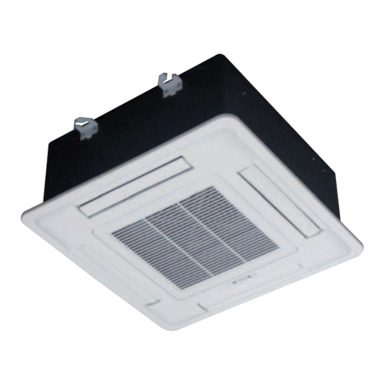
- FAN COIL CASSETTE
MODELS
EN) Please read this guide carefully before
switching on the appliance.
a-CHD U-2T 606÷2209
a-CHD U-4T 706÷2209
I-Chd U-2T 706÷2209
Advertisement
Table of Contents

Related Manuals for CLIMAVENETA a-CHD U-2T 606+2209


Summary of Contents for CLIMAVENETA a-CHD U-2T 606+2209
- Page 1 OPERATING AND INSTALLATION MANUAL - FAN COIL CASSETTE MODELS a-CHD U-2T 606÷2209 a-CHD U-4T 706÷2209 i-CHD U-2T 706÷2209 EN) Please read this guide carefully before switching on the appliance.
-
Page 2: Table Of Contents
AFTER SALES DEPARTMENT - RESIDENTIAL BUSINESS Via Duca d’Aosta 121 - 31031 Mignagola di Carbonera (TV) ITALY Tel: +39.0424.509500 - Fax: +39.0424.509563 www.climaveneta.com - info@climaveneta.com DESCRIPTION OF THE APPLIANCE The fan coils are appliances intended for high quality civil WALL-MOUNTED CONTROL use. -
Page 3: Application
APPLICATION General CAREFULLY READ THIS MANUAL BEFORE INSTALLING The appliances are supplied with hot/cold water depending THE APPLIANCE on whether the environment is being heated/cooled. The Cassette fan coil are designed for use in commercial and private environments with false ceilings. The Cassette The manufacturer/seller cannot be held liable for any loss or fan-coil units are exclusively built for air heating, filtering, damage caused as a result of incorrect... -
Page 4: Basic Safety Rules
BASIC SAFETY RULES General Using electrically-operated products implies the observance • Fan-coil units should only be carried at suitable points. of certain basic safety rules, such as those given below: When carrying fan-coil units, gloves should be worn for safety reasons. Using electrically-operated products implies the observance •... -
Page 5: Operating Limits
OPERATING LIMITS General Cassette fan-coil and heat exchanger: Valves with thermoelectric actuator: • Maximum temperature of heat vector fluid = 80°C • Refer to instruction sheet present inside kit valve-unit. • Minimum temperature of refrigerant fluid: min 2°C • Maximum working pressure: 1400 KPa Other technical data •... -
Page 6: Unit Drawings
PROJECT SPECIFICATIONS General PROJECT SPECIFICATIONS i-CHD U-2T Frame in galvanised steel insulated with self-extinguishing Hydraulic connections. Manual air valve with outlet connect- closed-cell polyethylene blanket of suitable thickness to limit ed to the condensate collecting tray. Plastic condensate col- heat loss and noise to a minimum. Airflow grille in ABS. lecting tray housing the condensate drain pump and float. - Page 7 UNIT DRAWINGS General a-CHD U-2T 1108 a-CHD U-2T 2209 i-CHD U-2T 1108 i-CHD U-2T 2209 G3/4" water outlet Drainage Drainage G3/4" water outlet Drain hole for external drain pan G3/4" water intel G3/4" water intel Drain hole for external drain pan Mounting Mounting brackets...
- Page 8 UNIT DRAWINGS General a-CHD U-4T 706 a-CHD U-4T 1108 G3/4"hot water outlet G3/4"chilled water outlet G3/4"hot water outlet G3/4"chilled water outlet Drainage Drainage G3/4"chilled water inlet Drain hole for external drain pan G3/4"hot water inlet G3/4"hot water inlet Drain hole for external drain pan G3/4"chilled water inlet Mounting brackets...
- Page 9 UNIT DRAWINGS General a-CHD U-4T 2209 G3/4"hot water outlet G3/4"chilled water outlet Drainage G3/4"chilled water inlet Drain hole for external drain pan G3/4"hot water inlet Mounting brackets Fresh Air Flange Ø100 branch duct...
-
Page 10: Technical Data
TECHNICAL DATA General a-CHD U-2T Models a-CHD 606 a-CHD 706 a-CHD 1108 a-CHD 2209 Version U-2T U-2T U-2T U-2T Air flow rate Vel.5* 1380 Vel.4 1640 Vel.3* 1970 Vel.2 1050 2130 Vel.1* 1300 2250 Total cooling capacity (1) Vel.5* 1,41 3,57 7,69 Vel.4... - Page 11 TECHNICAL DATA General a-CHD U-4T Models a-CHD 706 a-CHD 1108 a-CHD 2209 Version U-4T U-4T U-4T Air flow rate Vel.5* 1090 Vel.4 1640 Vel.3* 1970 Vel.2 1050 2130 Vel.1* 1300 2250 Total cooling capacity (1) Vel.5* 2,42 3,18 5,36 Vel.4 2,76 5,46 5,99...
- Page 12 TECHNICAL DATA General i-CHD U-2T Models i-CHD 706 i-CHD 1108 i-CHD 2209 Version U-2T U-2T U-2T Air flow rate Vel.3 Vel.2 1380 Vel.1 1300 2100 Total cooling capacity (1) Vel.3 1,41 3,13 5,87 Vel.2 3,28 Vel.1 4,56 10,6 Sensible cooling capacity (1) Vel.3 1,11 2,52...
- Page 13 DROP PRESSURE AND CORRECTION FACTOR General 2-pipe units (without valve assembled) 1108 2209 800 1000 1200 1400 1600 1800 2000 (l/h) 4-pipe units in COOLING mode (without valve assembled) 1108 2209 (l/h) 4-pipe units in HEATING mode (without valve assembled) 1108 2209 (l/h)
- Page 14 INDOOR UNIT INSTALLATION Installation WHERE TO INSTALL INDOOR UNIT There should not be any heat source or steam near the unit. Where there is no obstacle in the air passages in >100 cm and out of the unit. Cassette has to be installed in: •...
-
Page 15: Installation Installation
INSTALLATION OF VALVE UNIT Installation • To install the valves, see the instructions shown on the If the proposed connections are not respected, there will valve kit instruction sheet. To make the connection to the be the risk that the water overflows from the condensate Cassette, please make reference to the unit drawings. - Page 16 DUCT INSTALLATION Installation Fresh Air Duct dimension (mm)
- Page 17 DUCT INSTALLATION Installation Ductable outlet air connections Branch Duct Connection CHD – cassette units have primary air flow connection. • The side opening allows separate ductwork to be installed They are equipped with inlets for treated air on the corner of for branch ducting.
- Page 18 DUCT INSTALLATION Installation Branch Duct Installation Procedure 1. Look for the yellow sticker on the casing for location of 3. Knock out the pre-cut hole. branch duct or fresh air intake connections. 4. Connect the flange on to the opening with Φ3 mm. x 12 2.
- Page 19 WATER CONNECTIONS Installation a-CHD U-2T 1108 a-CHD U-2T 2209 i-CHD U-2T 1108 i-CHD U-2T 2209 G3/4" water outlet Drainage Drainage G3/4" water outlet Drain hole for external drain pan G3/4" water intel G3/4" water intel Drain hole for external drain pan a-CHD U-4T 706 a-CHD U-4T 1108 G3/4"hot water outlet...
- Page 20 WATER CONNECTIONS Installation • When a piping is connected to the unit main body or removed from it, be sure to use two wrenches to fasten it. (See the figure 1) Carefully insulate pipes, valve assemblies and coil con- nections to avoid condensation forming on the pipes and dripping on the false ceiling.
-
Page 21: Valve Unit Installation
ELECTRICAL CONNECTION Installation • To access the unit’s electrical panel, remove the air grille Power supply, control and valve wiring and remove the electrical box cover, as shown in Figure 1. The fan coils feature a board with screw terminal block for connecting the wires from the wall-mounted controller and the valves. - Page 22 ELECTRICAL CONNECTION Installation Louver control Control of louver opening can be managed: 1. Manually (standard configuration) 2. Automatically: during installation, automatic louver opera- tion can be set up by connecting the special motor power supply cables available on the unit (accessible through the grill opening) to the main terminal block in the electri- cal box (see Fig.
- Page 23 ELECTRICAL CONNECTION Installation Mounting Front Panel Assembly 1. Remove return grille from front panel. 2. Move the front panel to casing. 3. Tighten 4 screws as shown in Figure 1 and Figure 2.
- Page 24 ELECTRICAL CONNECTION Installation a-CHD 606÷2209 C65403161F ATTENTION FACTORY WIRING STEP. STEP. Pre-wired sensor cable. FIELD WIRING For use when connecting MOTOR MOTOR to ~S FULL CONTROL 3 + 4 1 + 2 WIRING CONNECTIONS ALARM (NC) X-DIS TO THERMOSTAT RELAY HIGH FAN SPEED 230VAC MEDIUM FAN SPEED...
- Page 25 ELECTRICAL CONNECTION Installation i-CHD 706÷2209 FACTORY Black WIRING Blue Cooling Valve Orange FIELD Heating Valve Brown WIRING AUTO ON/OFF iK - EKW NOTE: AUTO ON/OFF SIGNAL CONNECT TS2 ONLY WITH 4 PIPE UNIT. Grey LOW VOLTAGE MODULATING SIGNAL LEGEND: Green 0-10 Vdc NOTE: EKW Wall-mounted Environment Thermostat...
- Page 26 ELECTRICAL CONNECTION Installation Single electrical connections: cassette unit with wall-mounted control For electrical connections of CHD cassette fan-coil refer to following electrical diagrams. Do not refer to wiring dia- grams present on instruction sheet of wall-mounted controls. a-CHD 606÷2209 + ATW - MTW FIELD WIRING WATER TEMP.
- Page 27 ELECTRICAL CONNECTION Installation Single electrical connections: cassette unit with wall-mounted control For electrical connections of CHD cassette fan-coil refer to following electrical diagrams. Do not refer to wiring dia- grams present on instruction sheet of wall-mounted controls. i-CHD 706÷2209 + ATW - MTW FIELD WIRING WATER TEMP.
- Page 28 ELECTRICAL CONNECTION Installation Multiple connection cassette fan-coil with wall-mounted controls For electrical connections of CHD cassette fan-coil refer to following electrical diagrams. Do not refer to wiring dia- grams present on instruction sheet of wall-mounted controls. a-CHD 606÷2209 + ATW - MTW...
- Page 29 ELECTRICAL CONNECTION Installation Multiple connection cassette fan-coil with wall-mounted controls For electrical connections of CHD cassette fan-coil refer to following electrical diagrams. Do not refer to wiring dia- grams present on instruction sheet of wall-mounted controls. i-CHD 706÷2209 + ATW - MTW...
- Page 30 ELECTRICAL CONNECTION Installation Single electrical connections: cassette unit with wall-mounted control For electrical connections of CHD cassette fan-coil refer to following electrical diagrams. Do not refer to wiring dia- grams present on instruction sheet of wall-mounted controls. i-CHD 706÷2209 + iK + EKW + iHB Black Blue FIELD WIRING...
- Page 31 ELECTRICAL CONNECTION Installation Multiple connection cassette fan-coil with wall-mounted controls For electrical connections of CHD cassette fan-coil refer to following electrical diagrams. Do not refer to wiring dia- grams present on instruction sheet of wall-mounted controls. i-CHD 706÷2209 + iK + EKW + iHB...
-
Page 32: Wall-Mounted Controls
WALL-MOUNTED CONTROLS User MTW wall-mounted control The MT control is used to regulate the air (3 speeds), the temperature through electronic thermostat, to select the sum- mer/winter mode of operation and to switch the fan coil on/off. Function selector Temperature selecto Adjust the temperature as Cooling required by... - Page 33 WALL-MOUNTED CONTROLS User DESCRIPTION OF FUNCTIONS CONFIGURATION OF THE MTW CONTROL SUMMER mode of operation Analog inputs The Summer mode is selected by setting the mode selector Air sensor input included in MTW control: on the relative symbol . In this mode the resources are - analog input used for temperature control.
- Page 34 WALL-MOUNTED CONTROLS User ATW wall-mounted control The ATW control is used to regulate the air (3 speeds + auto), the temperature through electronic thermostat, to select the sum- mer/winter/auto mode of operation and to switch the fan coil on/off. Temperature selector Speed selector Adjust the temperature as Select the fan speed pushing the...
- Page 35 WALL-MOUNTED CONTROLS User DESCRIPTION OF FUNCTIONS CONFIGURATION OF THE ATW CONTROL SUMMER mode of operation Analog inputs The Summer mode is selected by setting the mode selector Air sensor input included in ATW control: on the relative symbol - analog input used for temperature control. In this mode the resources are managed as follows: Water sensor input (kit included): - the summer mode valve is always ON;...
- Page 36 CHD. Easy control installation thanks to 2 wires connection. EKW control could be installed in Building Management System (e.g. Idrorelax system by Climaveneta) via Modbus protocol. Temperature selector Speed selector...
- Page 37 WALL-MOUNTED CONTROLS User DESCRIPTION OF FUNCTIONS Hot Start function This function is available in the heating mode and it only SUMMER mode of operation activates the fan if the water is hot enough. It is not available The Summer mode is selected by setting the mode selector if the heating element is installed.
- Page 38 WALL-MOUNTED CONTROLS User i-HB POWER BOARD i-HB power board gives electrical supply to i-CHD managing • Installation in Master-Slave network with two wires con- EC fan brushless motor. nection • Addressing dip-switch for multiple installation as well as i-HB power board has the following technical characteristics: plant configuration •...
- Page 39 Building Management Sys- coil. Interface with LCD screen with user-friendly icons. Con- tem (e.g. Idrorelax system by Climaveneta) via Modbus pro- trol kit for universal wall-mounted installation. tocol. Installation and management of Master-Slave system Selection of functioning mode (OFF/summer/winter/AUTO), up to 8 units without any additional interfaces.
- Page 40 WALL-MOUNTED CONTROLS User WINTER mode of operation Weekly timer operation The Winter mode is selected by setting the mode selector iK offers weekly timer function, according with 4 preset pro- on the relative symbol grams and 1 program configurable by end-user. Tempera- In this mode the resources are managed as follows: ture set-point could be managed on three levels (T1, T2, - the summer mode valve is always OFF;...
- Page 41 MAINTENANCE Service CLEANING THE AIR FILTERS Before inspection and maintenance of the unit, always set the main power switch to “OFF” to cut off power sup- ply. • Remove the air grille from the front frame, using the catch- • Remove the air filter as shown in the figure. •...
-
Page 42: Operating Guide
MAINTENANCE Service Fan-coil units must be disconnected from mains power and HEAT EXCHANGER COIL: secured against unintentional re-connection before any No ordinary maintenance required. maintenance work. All work must be in accordance with all applicable safety and health rules and regulations. FILTER: Filter Maintenance The filter pad may be cleaned or Using a suitable tool, unhook the filter holder strip and... -
Page 43: Malfunction And Corrective Actions
MALFUNCTIONS AND CORRECTIVE ACTIONS Service MALFUNCTION POSSIBLE CAUSES CORRECTIVE ACTION Fan does not run Fan coil unit not switched on Switch on fan-coil unit No power Check fusing/mains power Cabling not connected Connect cabling (qualified person only) The supply is stopped by the float switche Verify the float Low air flow Low fan speed... - Page 44 88 Bai Yun Rd, Pudong Xinghuo New dev. zone 201419 Shanghai China Tel 008 621 575 055 66 Fax 008 621 575 057 97 Climaveneta Polska Sp. z o.o. Ul. Sienkiewicza 13A 05-120 Legionowo Poland Tel +48 22 766 34 55-57 Fax +48 22 784 39 09 info@climaveneta.pl...