Table of Contents
Advertisement
OPERATING AND INSTALLATION MANUAL
I
- VENTILCONVETTORE CASSETTE
GB
- FAN COIL CASSETTE
FR
- VENTILO-CONVECTEURS CASSETTE
DE
- KASSETTEN-KLIMAKONVEKTOREN
ES
- VENTILADORES CONVECTORES CASSETTE
MODELLI
MODELS
MODÈLES
MODELLE
MODELOS
I)
Vi preghiamo di leggere con attenzione
il presente manuale prima di mettere in
funzione l'apparecchio.
GB) Please read this guide carefully before
switching on the appliance.
FR) Nous vous prions de bien vouloir lire
attentivement ce mode d'emploi avant
de mettre l'appareil en fonction.
DE) Bitte lesen Sie vor der Inbetriebnahme
des Geräts aufmerksam diese
Bedienungsanleitung.
ES) Les rogamos lean con atención el
presente manual antes de encender el
aparato.
CHD U-2T 506-1209
CHD U-4T 506-1209
Advertisement
Table of Contents

Related Manuals for CLIMAVENETA CHD U-2T 506


Summary of Contents for CLIMAVENETA CHD U-2T 506
- Page 1 - VENTILCONVETTORE CASSETTE - FAN COIL CASSETTE - VENTILO-CONVECTEURS CASSETTE - KASSETTEN-KLIMAKONVEKTOREN - VENTILADORES CONVECTORES CASSETTE MODELLI MODELS CHD U-2T 506-1209 MODÈLES CHD U-4T 506-1209 MODELLE MODELOS Vi preghiamo di leggere con attenzione il presente manuale prima di mettere in funzione l’apparecchio.
-
Page 2: Table Of Contents
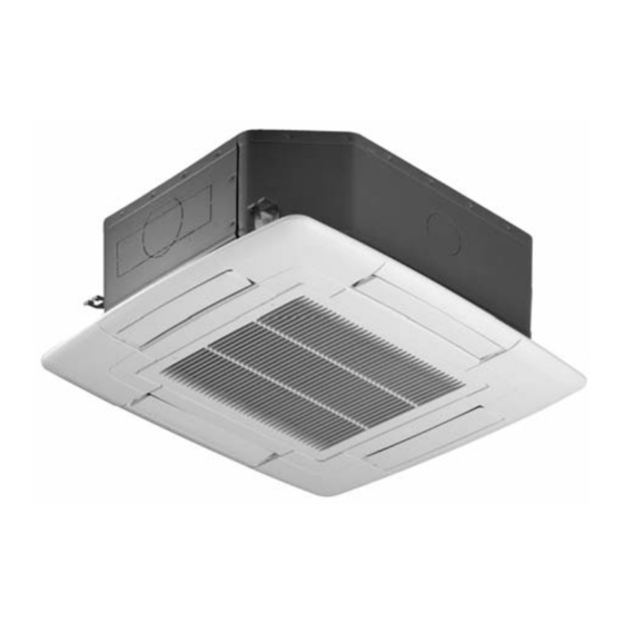
AFTER SALES DEPARTMENT - RESIDENTIAL BUSINESS Via Duca d’Aosta 121 - 31031 Mignagola di Carbonera (TV) ITALY Tel: +39.0424.509500 - Fax: +39.0424.509563 www.climaveneta.com - info@climaveneta.com DESCRIPTION OF THE APPLIANCE The fan coils are appliances intended for high quality civil and aluminium fins use. -
Page 3: Application
APPLICATION General CAREFULLY READ THIS MANUAL BEFORE INSTALLING The appliances are supplied with hot/cold water depending THE APPLIANCE on whether the environment is being heated/cooled. The Cassette fan coil are designed for use in commercial and private environments with false ceilings. The Cassette The manufacturer/seller cannot be held liable for any loss or fan-coil units are exclusively built for air heating, filtering, damage caused as a result of incorrect... -
Page 4: Chd U-2T 606
BASIC SAFETY RULES General Using electrically-operated products implies the observance When carrying fan-coil units, gloves should be worn for of certain basic safety rules, such as those given below: safety reasons. • Lifting tackle and gear must have sufficient capacity. Using electrically-operated products implies the observance •... -
Page 5: Chd U-2T 706
OPERATING LIMITS General Cassette fan-coil and heat exchanger: Other technical data • Maximum temperature of heat vector fluid = 80°C All other important technical data (dimensions, weights, con- • Minimum temperature of refrigerant fluid = 5°C nections, noise emissions, etc.) are given elsewhere in this •... -
Page 6: Unit Drawings
UNIT DRAWINGS General CHD U-2T 506-706 CHD U-4T 506-706 CHD U-2T 809-1209 CHD U-4T 809-1209... -
Page 7: Technical Data
TECHNICAL DATA General Models CHD 506 CHD 606 CHD 706 CHD 809 CHD 1109 CHD 1209 Version U-2T U-2T U-2T U-2T U-2T U-2T Air flow rate Turbo speed 1050 1400 1700 1800 Max speed 1100 1300 1400 Med speed 1100 1200 Min speed Total cooling capacity (1) -
Page 8: Chd U-4T 1109
TECHNICAL DATA General Models CHD 506 CHD 606 CHD 706 CHD 909 CHD 1109 CHD 1209 Versione U-4T U-4T U-4T U-4T U-4T U-4T Air flow rate Turbo speed 1050 1500 1700 1800 Max speed 1150 1300 1400 Med speed 1100 1200 Min speed Total cooling capacity (1) -
Page 9: Chd U-2T 1109
CHD 506 - 706 MODELS (U-2T E U-4T VERSION) Unit pressure drop (2-Pipe) Unit pressure drop (4-Pipe) (without valve assembly) (without valve assembly) CHD U-4T 506 -706 (HEATING CIRCUIT) CHD U-2T 506 - 706 CHD U-4T 506 -706 (COOLING CIRCUIT) Model Capacity Fan speed Turbo Max... - Page 10 DROP PRESSURE AND CORRECTION FACTOR General CHD 809 - 1209 MODELS (U-2T E U-4T VERSION) Unit pressure drop (2-Pipe) Unit pressure drop (4-Pipe) (without valve assembly) (without valve assembly) CHD 909 - 1209 CHD 809 CHD 909 - 1209 CHD 909 - 1209 CHD 809 CHD 909 - 1209 CHD 809...
-
Page 11: Chd U-2T 1209
INDOOR UNIT INSTALLATION Installation WHERE TO INSTALL INDOOR UNIT There should not be any heat source or steam near the unit. Where there is no obstacle in the air passages in and out of the unit. Cassette has to be installed in: •... -
Page 12: Valve Unit Installation
INSTALLATION OF VALVE UNIT Installation • For the installation of the valves, follow the instruction of The valves used must stop the entering of the water the producer; to make the connection to the Cassette, when there is no electrical feeding. please make reference to the unit drawings. - Page 13 WATER CONNECTIONS Installation Typical water piping diagram Field supply Water in Shut off valve Water out Fan coil unit Water out Shut off valve Water in 3-way motorized valve CHD 506-706 CHD 809-1209 2 Pipe 2 Pipe 4 Pipe 4 Pipe...
-
Page 14: Hydraulic Connections
WATER CONNECTIONS Installation • When a piping is connected to the unit main body or removed from it, be sure to use two wrenches to fasten it. (See the figure) Carefully insulate pipes, valve assemblies and coil con- nections to avoid condensation forming on the pipes and dripping on the false ceiling. -
Page 15: Auxiliary Tray Installation
WATER CONNECTIONS Installation Auxiliary tray installation CHD 506-706 (U-2T e U-4T) INSULATION SCREW M4x20MM SCREW M4x20MM 1. REMOVE THE PLASTIC CAP SCREW M4x20MM 2. INSTALLATION AUXILIARY DRAIN PAN Auxiliary tray installation CHD 809-1209 (U-2T e U-4T) SCREW 3 M4x20MM 1. REMOVE THE PLASTIC CAP 2. -
Page 16: Electrical Connections
ELECTRICAL CONNECTION Installation Connection instruction Electrical characteristic • The motor is protected by a thermal contact integrated in Perform electrical connections in accordance with laws the winding. It stops the motor if overheating occurs and and regulations in force in the country concerned. starts the motor again automatically after it has cooled Always disconnect the electrical power supply before down. - Page 17 ELECTRICAL CONNECTION Installation CHD 506 - 706 CHD 809 - 1209...
- Page 18 ELECTRICAL CONNECTION Installation Single electrical connections: cassette unit with wall-mounted control For electrical connections of CHD cassette fan-coil refer to following electrical diagrams. Do not refer to wiring dia- grams present on instruction sheet of wall-mounted controls. CHD 506÷706 + NSW CHD 809÷1209 + NSW...
- Page 19 ELECTRICAL CONNECTION Installation Single electrical connections: cassette unit with wall-mounted control For electrical connections of CHD cassette fan-coil refer to following electrical diagrams. Do not refer to wiring dia- grams present on instruction sheet of wall-mounted controls. CHD 506÷706 + ATW-MTW-PSW CHD 809÷1209 + ATW-MTW-PSW...
- Page 20 ELECTRICAL CONNECTION Installation Multiple connection cassette fan-coil with wall-mounted controls For electrical connections of CHD cassette fan-coil refer to following electrical diagrams. Do not refer to wiring dia- grams present on instruction sheet of wall-mounted controls. CHD 506÷706 + SPB + NSW...
- Page 21 ELECTRICAL CONNECTION Installation Multiple connection cassette fan-coil with wall-mounted controls For electrical connections of CHD cassette fan-coil refer to following electrical diagrams. Do not refer to wiring dia- grams present on instruction sheet of wall-mounted controls. CHD 809÷1209 + SPB + NSW...
-
Page 22: Wall-Mounted Controls
ELECTRICAL CONNECTION Installation Multiple connection cassette fan-coil with wall-mounted controls For electrical connections of CHD cassette fan-coil refer to following electrical diagrams. Do not refer to wiring dia- grams present on instruction sheet of wall-mounted controls. CHD 506÷706 + SPB + ATW + MTW + PSW... - Page 23 ELECTRICAL CONNECTION Installation Multiple connection cassette fan-coil with wall-mounted controls For electrical connections of CHD cassette fan-coil refer to following electrical diagrams. Do not refer to wiring dia- grams present on instruction sheet of wall-mounted controls. CHD 809÷1209 + SPB + ATW + MTW + PSW...
-
Page 24: User
WALL-MOUNTED CONTROLS User NSW wall-mounted control The NSW control is used to regulate the air (3 speeds), the temperature through electronic thermostat, to select the sum- mer/winter mode of operation and to switch the fan coil on/off and hot start function by minimun thermostat kit. Function selector Cooling Riscaldamento... - Page 25 WALL-MOUNTED CONTROLS User DESCRIPTION OF FUNCTIONS CONFIGURATION OF THE NSW CONTROL SUMMER mode of operation Digital outputs The Summer mode is selected by setting the mode selector YV1 Valve control (max 1,5 A). on the relative symbol . In this mode the resources are This is used for opening of the delivery valve and the conse- managed as follows: quent flow of water into the coil, as described below:...
- Page 26 WALL-MOUNTED CONTROLS User PSW wall-mounted control The PSW control is used to regulate the airflow (3 speeds), select the summer/winter mode of operation and switch the fan coil on/off and hot start function by minimun thermostat kit. Function selector Cooling Riscaldamento Fan selector Maximum fan speed...
- Page 27 WALL-MOUNTED CONTROLS User DESCRIPTION OF FUNCTIONS CONFIGURATION OF THE PSW CONTROL SUMMER mode of operation Digital outputs The Summer mode is selected by setting the mode selector YV1 Valve control (max 1,5 A). on the relative symbol . In this mode the resources are This is used for opening of the delivery valve and the conse- managed as follows: quent flow of water into the coil, as described below:...
- Page 28 WALL-MOUNTED CONTROLS User MTW wall-mounted control The MT control is used to regulate the air (3 speeds), the temperature through electronic thermostat, to select the sum- mer/winter mode of operation and to switch the fan coil on/off. Function selector Temperature selecto Adjust the temperature as Cooling required by...
- Page 29 WALL-MOUNTED CONTROLS User DESCRIPTION OF FUNCTIONS CONFIGURATION OF THE MTW CONTROL SUMMER mode of operation Analog inputs The Summer mode is selected by setting the mode selector Air sensor input included in MTW control: on the relative symbol . In this mode the resources are - analog input used for temperature control.
- Page 30 WALL-MOUNTED CONTROLS User ATW wall-mounted control The ATW control is used to regulate the air (3 speeds + auto), the temperature through electronic thermostat, to select the sum- mer/winter/auto mode of operation and to switch the fan coil on/off. Temperature selector Speed selector Adjust the temperature as Select the fan speed pushing the...
- Page 31 WALL-MOUNTED CONTROLS User DESCRIPTION OF FUNCTIONS CONFIGURATION OF THE ATW CONTROL SUMMER mode of operation Analog inputs The Summer mode is selected by setting the mode selector Air sensor input included in ATW control: on the relative symbol - analog input used for temperature control. In this mode the resources are managed as follows: Water sensor input (kit included): - the summer mode valve is always ON;...
-
Page 32: Maintenance
MAINTENANCE Service CLEANING THE AIR FILTERS Before inspection and maintenance of the unit, always set the main power switch to “OFF” to cut off power sup- ply. • Unclip the grille from the front frame by turn the two crews through 90º... -
Page 33: Operating Guide
MAINTENANCE Service Fan-coil units must be disconnected from mains power and HEAT EXCHANGER COIL: secured against unintentional re-connection before any No ordinary maintenance required. maintenance work. All work must be in accordance with all applicable safety and health rules and regulations. FILTER: Filter Maintenance The filter pad may be cleaned or Using a suitable tool, unhook the filter holder strip and... -
Page 34: Malfunction And Corrective Actions
MALFUNCTIONS AND CORRECTIVE ACTIONS Service MALFUNCTION POSSIBLE CAUSES CORRECTIVE ACTION Fan does not run Fan coil unit not switched on Switch on fan-coil unit No power Check fusing/mains power Cabling not connected Connect cabling (qualified person only) The supply is stopped by the float switche Verify the float Low air flow Low fan speed... - Page 38 88 Bai Yun Rd, Pudong Xinghuo New dev. zone 201419 Shanghai China Tel 008 621 575 055 66 Fax 008 621 575 057 97 Climaveneta Polska Sp. z o.o. Ul. Sienkiewicza 13A, 05-120 Legionowo, Poland Tel +48 22 766 34 55-57 Fax +48 22 784 39 09 info@climaveneta.pl...