Makita HR4500C Manual
Hide thumbs
Also See for HR4500C:
- Instruction manual (52 pages) ,
- Parts list (3 pages) ,
- Instruction manual (29 pages)
Table of Contents
Advertisement
Quick Links
Download this manual
See also:
Instruction Manual
T
ECHINICAL INFORMATION
Models No.
Description
C
ONCEPTION AND MAIN APPLICATIONS
For matured line-up of SDS-Max Rotary Hammers, Model HR4500C
has been developed as a sister model to HR4000C(40mm;1-3/4") and
HR5001C(50mm;2") which are already popular to users around the
world.
Performing excellent drilling in concrete within the diameter range
from 25mm(1") to 45mm(1-3/4"), it also has the same features and
benefits as HR4000C and HR5001C.
See next page for detailed information.
Specifications
Voltage (V) Current (A) Cycle (Hz)
100
15
110
13
120
13
220
6.6
230
6.6
240
6.8
No load speed
Bit type
Diameter of shank : mm (")
Drilling capacities
: mm (")
Net weight : Kg (lbs)
Cord length : m (ft)
STANDARD EQUIPMENT
Depth Gauge ----------------------- 1pc.
Grease Vessel (Bit Grease) ------- 1pc.
Plastic Carrying Case ------------- 1pc.
Side Handle Assembly
(D-shaped side handle) ----------- 1pc.
Grip 36 Assembly
(Bar style side handle) ------------ 1pc.
The standard equipment for the machine may differ from country to country.
OPTIONAL ACCESSORIES
Hammer Grease (30cc), Blow-out Bulb, Dust Cup 5, Dust Cup 9, Bull Point, Cold Chisel, Scaling Chisel,
Clay Spade, Bushing Tool, Rammer, Safety Goggles, Core Bit Adapter,
Core Bits; Hole diameter : 20mm(13/16"), 30mm(1-3/16"), 35mm(1-3/8"), 40mm(1-9/16"), 45mm(1-3/4"),
Tungusten-carbide Tipped Bits; Bit diameter : 10mm(3/8"), 10.5mm(7/16"), 11mm(7/16"), 12mm(15/32"),
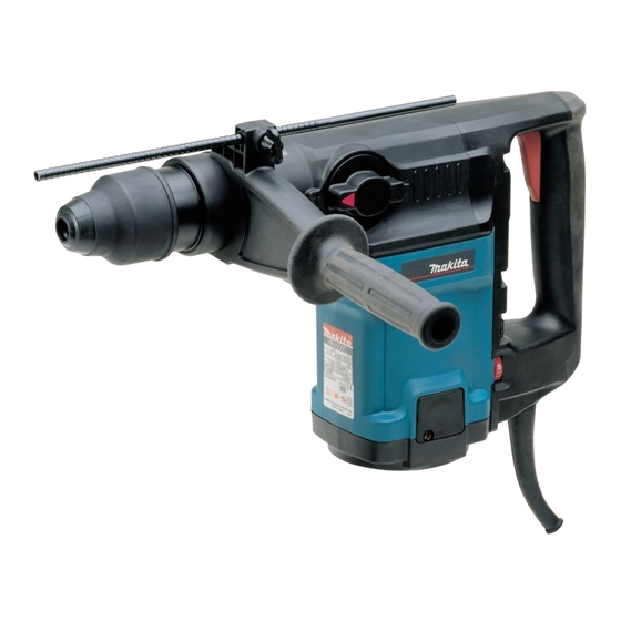
HR4500C
Rotary Hammer 45mm (1-3/4")
Continuous Rating (W)
Input
50/60
1,300
50/60
1,300
50/60
1,250
50/60
1,300
1,300
50/60
50/60
1,300
Rotations per minute : rpm=min-
Blows per minute : bpm=min-
Tungusten-carbide
tipped bit
Core bit
54mm(2-1/8"), 65mm(2-9/16"), 79mm(3-1/8"), 105mm(4-1/8"), 118mm(4-5/8")
12.5mm(1/2"), 12.7mm(1/2"), 13.5mm(1/2"), 14.3mm(9/16"),
14.5mm(9/16"), 16mm(5/8"), 17mm(11/16"), 17.5mm(11/16"),
18mm(11/16"), 19mm(3/4"), 20mm(13/16"), 21.5mm(7/8"),
22mm(7/8"). 24mm(15/16"), 25mm(1"), 25.4mm(1"), 26mm(1"),
28mm(1-1/8"), 30mm(1-3/16"), 32mm(1-1/4"), 35mm(1-3/8"),
38mm(1-1/2")
Max. Output(W)
Output
600
1,500
600
1,500
600
1,500
1,500
600
600
1,500
600
1,500
120 - 240
1
1,250 - 2,550
1
SDS-Max shank bit
18 (11/16")
45 (1-3/4")
125 (4-7/8")
7.8 (17.2)
Standard spec. : 5 (16.4)
European spec. : 4 (13.1)
PRODUCT
P 1 / 16
L
H
W
Dimensions : mm ( " )
Length (L)
488mm (19-1/4")
Width (W)
118mm (4-5/8")
Height (H)
278mm (11")
Advertisement
Table of Contents

Related Manuals for Makita HR4500C


Summary of Contents for Makita HR4500C
- Page 1 HR4500C Description Rotary Hammer 45mm (1-3/4") ONCEPTION AND MAIN APPLICATIONS For matured line-up of SDS-Max Rotary Hammers, Model HR4500C has been developed as a sister model to HR4000C(40mm;1-3/4") and HR5001C(50mm;2") which are already popular to users around the world. Performing excellent drilling in concrete within the diameter range from 25mm(1") to 45mm(1-3/4"), it also has the same features and...
- Page 2 P 2 / 16 Features and benefits The Outstanding Chipping Power in This Class See next page for the excellent results of various chipping/drilling tests. No electric shock to operator, even if bit accidentally hits against laid electric cables. Body Wholly Covered Barrel is also covered with resin, and so, it is possible to do chipping operations while with Resin holding barrel with your hand.
- Page 3 : concrete whose compressive strength is 350 kgf/cm in horizontal application The results are shown in relative values when setting Model A-a of competitor A's data as 100. Chipping amount Much Little HR4500C HR5001C HR3850 HR4000C Drilling speed 1. ø25mm hole...
-
Page 4: Hr4500C
P 4 /16 Comparison of products Competitor B Makita Makita Competitor A Model No. HR4500C HR4000C HR5001C A-1C Continuous rating 1,300 1,300 1,050 1,150 1,050 1,500 Input (W) Continuous rating 11.7 current (A) on 120V 0 - 200 No load speed... -
Page 5: Hr4500C
P 5 / 16 epair < 1 > Lubrication Apply MAKITA grease No.00 to the following parts in order to prevent unusual abrasion and overheating. Oil seal 35 Apply to the lip portion. Apply to the whole part of Impact bolt. -
Page 6: Hr4500C
P 6 / 16 epair <3> Assembling Change Lever Upper hole of change link 1) Change link is constructed to be slid up and down. Slide the change link upward with your finger. (See Fig.2) Change link slid upward with finger 2) Assemble change lever on crank housing Figure 2 with setting crank pin 4 into the upper hole (elliptic hole) - Page 7 P 7 / 16 epair 3) Insert a stainless scale into the change lever assembling hole of crank housing, and put the another end of the same scale on side handle base as illustrated in Fig. 5. 4) Strike side grip with plastic hammer. So crank housing cover can be separated together with side grip from crank housing as illustrated in Fig.
-
Page 8: Flat Washer 8
P 8 / 16 epair 9) Disassemble rear cover, brush holder cover, brush holder cap and carbon brush from motor housing as illustrated in Fig. 8. Fig. 8 Motor housing Carbon brush Brush holder cap Rear cover Brush holder cover Tapping screw M4x18 Tapping screws M5x20 10) Hold fan with your gloved hand. -
Page 9: Table Of Contents
P 9 / 16 epair <4> Assembling armature 1) Assemble oil seal 15 and ball bearing 6202LLU to gear housing as illustrated in Fig. 12. Press Oil seal 15 Gear housing Ball bearing 6202LLU Press Fig. 12 Fig. 12A 2) Assemble baffle plate and flat washer 15 to armature as illustrated in Fig. 13. And then, assemble the armature to gear housing by pressing. -
Page 10: Ring Spring 25
P 10 / 16 epair <6> Assembling chuck section 1) Assemble shoulder pin 8 to chuck ring. And then assemble leaf spring 37 to the chuck ring as illustrated in Fig. 15. <Note> The bulge of shoulder pin 8 has to meet the hole of leaf spring 37, when assembling leaf spring to chuck ring. -
Page 11: No.1R003
P 11 / 16 epair <8> Disassembling lock sleeve A and B from tool holder 1) Hold tool holder on which lock sleeve A and B are installed, by pressing with arbor press as illustrated in Fig. 17. 2) Disassemble retaining ring S-35 with No.1R003 "retaining ring S plier as illustrated in Fig. 17A. Hold by pressing with arbor press. - Page 12 P 12 / 16 epair <10> Disassembling crank shaft 1) Remove retaining ring R-55 which is fixing crank shaft, from crank housing as illustrated in Fig. 19. 2) Face the key installing groove of crank shaft to the side of crank housing by turning crank shaft as illustrated in Fig.
- Page 13 P 13 / 16 epair <12> Assembling reciprocating section 1) Assemble 2 pcs of O rings 35 to cylinder 34, and insert piston to which 2 pcs. of O rings 27 and rod have to be assembled in advance, into the cylinder 34 as illustrated in Fig. 21. And then, assemble flat washer 45 to crank housing.
- Page 14 P 14 / 16 epair <13> Assembling crank housing section 1. Assemble the the spare parts of Fig.23 into the crank housing. Slide sleeve Striker with Spiral Sleeve 19 Crank housing Washer 19 Ring 38 O ring 27 bevel gear 36 Rubber ring 22 Compression spring 39 Tool holder...
- Page 15 P 15 / 16 epair <15> Assembling torque limiter section 1. Assemble ball bearing 6001LLU, flat washer 12 (24mm in outer diameter) and torque limiter to spiral bevel gear 10. (see Fig. 26) Concave of Change key < Note > change key Be careful not to lose pin 4 for lock of circular nut.
- Page 16 P 16 / 16 ircuit diagram Color index of lead wires Black White Switch Field Controller iring diagram Pick-up coil Pass lead wire (red) as illustrated in Fig. A Motor housing Motor housing Set the slack portions of the following lead wires in the place illustrated Controller in Fig.