Table of Contents
Advertisement
Quick Links
USER GUIDE AND SPECIFICATIONS
NI USB-6008/6009
Introduction
This manual revision updates naming conventions to reflect the conventions used in
Note
NI-DAQmx. Table 1 notes the correlation between the old and updated names.
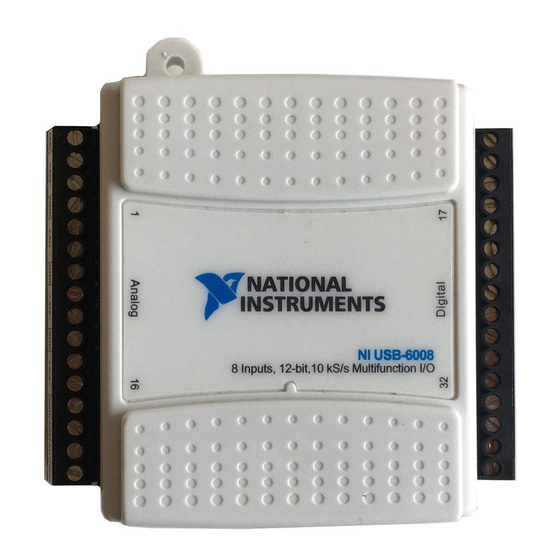
This guide describes how to use the National Instruments USB-6008/6009
data acquisition (DAQ) devices and lists specifications.
The NI USB-6008/6009 provides connection to eight analog input (AI)
channels, two analog output (AO) channels, 12 digital input/output (DIO)
channels, and a 32-bit counter with a full-speed USB interface.
Table 1. Digital Output Driver Type Naming Conventions
Hardware Functionality
Open-drain
Push-pull
NI-DAQmx Terminology
Open collector
Active drive
Advertisement
Table of Contents

Related Manuals for National Instruments 6008


Summary of Contents for National Instruments 6008
- Page 1 USER GUIDE AND SPECIFICATIONS NI USB-6008/6009 This guide describes how to use the National Instruments USB-6008/6009 data acquisition (DAQ) devices and lists specifications. Introduction The NI USB-6008/6009 provides connection to eight analog input (AI) channels, two analog output (AO) channels, 12 digital input/output (DIO) channels, and a 32-bit counter with a full-speed USB interface.
- Page 2 Table 2. Differences Between the NI USB-6008 and NI USB-6009 Feature AI Resolution Maximum AI Sample Rate, Single Channel Maximum AI Sample Rate, Multiple Channels (Aggregate) DIO Configuration System dependent. 1 USB Cable Strain Relief NI USB-6008/6009 User Guide and Specifications...
-
Page 3: Safety Guidelines
The following section contains important safety information that you must follow when installing and using the NI USB-6008/6009. Do not operate the NI USB-6008/6009 in a manner not specified in this document. Misuse of the device can result in a hazard. You can compromise the safety protection built into the device if the device is damaged in any way. - Page 4 MAINS is defined as a hazardous live electrical supply system that powers equipment. Suitably rated measuring circuits may be connected to the MAINS for measuring purposes. NI USB-6008/6009 User Guide and Specifications Measurement Category I is for measurements performed on circuits...
- Page 5 NI-DAQmx. The NI-DAQmx CD contains example programs that you can use to get started programming with the NI USB-6008/6009. Refer to the NI-DAQmx for USB Devices Getting Started Guide, that shipped with your device and is also accessible from Start»All Programs»National Instruments»...
- Page 6 Hardware The following block diagram shows key functional components of the NI USB-6008/6009. Vbus NI USB-6008/6009 User Guide and Specifications External Power +5 V/200 mA Supply USB Microcontroller P1.<0..3> P0.<0..7> +2.5 V/CAL 8 Channel 12/14b ADC AI <0..7> 12b DAC 12b DAC Figure 3.
-
Page 7: Setting Up Hardware
Install combicon screw terminal blocks by inserting them into the combicon jacks. Figure 4 illustrates the signal labels that ship in the NI USB-6008/6009 kit. You can apply the signal labels to the screw terminal blocks for easy signal identification. - Page 8 2 Combicon Jack Once you label the screw terminal blocks, you must only insert them into the Note matching combicon jack, as indicated by the overlay label on the NI USB-6008/6009 device. NI USB-6008/6009 User Guide and Specifications Figure 5. Signal Label Application Diagram Connect the wiring to the appropriate screw terminals.
- Page 9 I/O Connector The NI USB-6008/6009 ships with one detachable screw terminal block for analog signals and one detachable screw terminal block for digital signals. These terminal blocks provide 16 connections that use 16 AWG to 28 AWG wire. Table 3 lists the analog terminal assignments, and Table 4 lists the digital terminal assignments.
- Page 10 NI USB-6008/6009 User Guide and Specifications Table 4. Digital Terminal Assignments Module Terminal Signal P0.0 P0.1 P0.2 P0.3 P0.4 P0.5 P0 6 P0.7 P1.0 P1.1 P1.2 P1.3 PFI 0 +2.5 V +5 V ni.com...
-
Page 11: Signal Descriptions
Output reference for wrap-back testing. +5 V Power Source—Provides +5 V Output power up to 200 mA. Input PFI 0—This pin is configurable as either a digital trigger or an event counter input. NI USB-6008/6009 User Guide and Specifications Description... -
Page 12: Analog Input Circuitry
The NI USB-6008/6009 device has a green LED next to the USB connector. When the device is connected to a USB port, the LED blinks steadily to indicate that the device is initialized and is receiving power from the connection. -
Page 13: Analog Input Modes
(FIFO) buffer holds data during AI acquisitions to ensure that no data is lost. Analog Input Modes You can configure the AI channels on the NI USB-6008/6009 to take single-ended or differential measurements. Refer to Table 5 for more information about I/O connections for single-ended or differential measurements. - Page 14 GND. For example, if AI 1 is +10 V and AI 5 is –10 V, then the measurement returned from the device is +20 V. Connecting a signal greater than ±10 V on either pin results in a clipped output. NI USB-6008/6009 User Guide and Specifications –5 –10 –15 –20...
-
Page 15: Digital Trigger
Connecting Reference Single-Ended Voltage Signals To connect reference single-ended voltage signals (RSE) to the NI USB-6008/6009, connect the positive voltage signal to the desired AI terminal, and the ground signal to a GND terminal. When no signals are connected to the analog input terminal, the internal resistor divider may cause the terminal to float to approximately 1.4 V... -
Page 16: Analog Output Circuitry
Digital-to-analog converts (DACs) convert digital codes to analog voltages. Connecting Analog Output Loads To connect loads to the NI USB-6008/6009, connect the positive lead of the load to the AO terminal, and connect the ground of the load to a GND terminal. -
Page 17: Minimizing Glitches On The Output Signal
Refer to glitches. Digital I/O The NI USB-6008/6009 has 12 digital lines, P0.<0..7> and P1.<0..3>, which comprise the DIO port. GND is the ground-reference signal for the DIO port. You can individually program all lines as inputs or outputs. Digital I/O Circuitry Figure 13 shows P0.<0..7>... -
Page 18: Source/Sink Information
Caution are listed in the Specifications National Instruments is not liable for any damage resulting from such signal connections. Source/Sink Information The default configuration of the NI USB-6008/6009 DIO ports is open collector, allowing 5 V operation, with an onboard 4.7 kΩ pull-up resistor. -
Page 19: Power-On States
Each line has a weak pull-up resistor connected to it. Static DIO Each of the NI USB-6008/6009 DIO lines can be used as a static DI or DO line. You can use static DIO lines to monitor or control digital signals. All samples of static DI lines and updates of DO lines are software-timed. -
Page 20: Specifications
ADC using a multi-state regulator, amplifier, and filter circuit. The resulting +2.5 V reference voltage can be used as a signal for self test. +5 V Power Source The NI USB-6008/6009 supplies a 5 V, 200 mA output. This source can be used to power external components. Note While the device is in USB suspend, the output is disabled. - Page 21 14.7 7.73 4.28 3.59 2.56 , ±10 V, ±5 V, ±4 V, ±2.5 V, ±2 V, ±1.25 V, ±1 V trigger Maximum over Temperature (mV) Maximum over Temperature (mV) 84.8 58.4 53.1 45.1 Connecting NI USB-6008/6009 User Guide and Specifications...
- Page 22 Short circuit current ...50 mA Absolute accuracy (no load) ...7 mV typical, 36.4 mV maximum Digital I/O Digital I/O Direction control...Each channel individually Output driver type NI USB-6008/6009 User Guide and Specifications Typical at 25 °C (mV) 2.21 1.70 1.53 P0.<0..7>...
-
Page 23: External Voltage
Pull-up resistor ... 4.7 kΩ to 5 V Maximum input frequency... 5 MHz Minimum high pulse width ... 100 ns Minimum low pulse width ... 100 ns © National Instruments Corporation Level –0.3 — — — NI USB-6008/6009 User Guide and Specifications Units μA... -
Page 24: Bus Interface
Weight Screw-terminal wiring ...16 to 28 AWG Torque for screw terminals...0.22–0.25 N · m NI USB-6008/6009 User Guide and Specifications 4.10 to 5.25 VDC...80 mA typical, 500 mA max USB suspend ...300 μA typical, 500 μA max Without connectors...6.35 cm × 8.51 cm × 2.31 cm With connectors...8.18 cm ×... -
Page 25: Hazardous Locations
Safety Standards The NI USB-6008/6009 is designed to meet the requirements of the following standards of safety for electrical equipment for measurement, control, and laboratory use: • • Note For UL and other safety certifications, refer to the product label, or visit ni.com/certification... -
Page 26: Electromagnetic Compatibility
EMC for electrical equipment for measurement, control, and laboratory use: • • • The NI USB-6008/6009 may experience temporary variations in analog input Note readings when exposed to radiated and conducted RF noise. The device returns to normal operation after RF exposure is removed. Note For EMC compliance, operate this device according to product documentation. -
Page 27: Where To Go For Support
Instruments trademarks. Other product and company names mentioned herein are trademarks or trade names of their respective companies. For patents covering National Instruments products, refer to the appropriate location: Help»Patents in your software, the patents.txt file on your CD, or ni.com/patents.