Table of Contents
Advertisement
Quick Links
Advertisement
Table of Contents

Related Manuals for Ericsson EDACS ORION


Summary of Contents for Ericsson EDACS ORION
- Page 1 LBI-38888F Operator’s Manual ® EDACS ORION MOBILE RADIO...
- Page 2 Ericsson Inc., at any time and without notice. Such changes will be incorporated into new editions of this manual. No part of this manual may be reproduced or transmitted in any form or by any means, electronic or mechanical, including photocopying and recording, for any purpose, without the express written permission of Ericsson Inc.
-
Page 3: Table Of Contents
TABLE OF CONTENTS Page SAFETY INFORMATION ....INTRODUCTION ......USER INTERFACE . - Page 4 TABLE OF CONTENTS Page Adding Groups To A Scan List ....Deleting Groups From A Scan List ....Nuisance Delete .
- Page 5 TABLE OF CONTENTS Page DIRECT MODE OPERATION (Conventional System Only) . TRUNKED OR CONVENTIONAL MODE OPERATION . . . SIREN/LIGHT OPERATION ....AEGIS AND VOICE GUARD OPERATION ..Voice Modes .
-
Page 6: Safety Information
SAFETY INFORMATION The operator of any mobile radio should be aware of certain hazards com- mon to the operation of vehicular radio transmissions. A list of the possible hazards are: Explosive Atmospheres Just as it is dangerous to fuel a vehicle with the motor running, be sure to turn the radio off while fueling the vehicle. -
Page 7: Introduction
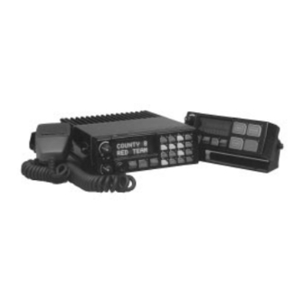
INTRODUCTION This manual describes how to use the EDACS ORION Mobile Radio. The ORION is a synthesized, microprocessor-based, high performance mobile FM radio providing reliable two-way communications in both the Enhanced Digital Access Communications System (EDACS) trunking environment and conventional communication systems. - Page 8 Figure 1 - EDACS ORION Mobile Radio SYSTEM Model Front Panel Figure 2 - EDACS ORION Mobile Radio SCAN Model Front Panel...
-
Page 9: Controls
CONTROLS This section describes the buttons, keys and rotary knobs used to control the Orion Scan and System Model radios. All functions and controls of the Scan radio operate the same as the corresponding functions and controls on the System radio. The Scan radio is equipped with a 4-button keypad and the System radio is equipped with a 16-button keypad. -
Page 10: Ramp Control
RAMP CONTROL The primary function of this rocker type button is to scroll through the System list or the Group/Channel list depend- ing upon programming. The secondary function is to in- crement or decrement items within a list (phone list for example). -
Page 11: Keypad
Figure 3 - ORION System Model Keypad Figure 4 - ORION Scan Model Keypad KEYPAD The keypad is similar to a telephone keypad but with four (4) additional but- tons on the side for a total of 16 keys. In addition to numbers (1-9, *, 0 and #), which is a secondary function, most of the keys have or can be pro- grammed to have a primary function. -
Page 12: Standard Keycap Configuration
Standard Keycap Configuration The Standard keycap package for the System radio includes five (5) labeled keycaps (MODE, HOME, CHN, AUX1 and AUX2) and six (6) blank key- caps, which can be placed on any of the five key locations (numbers 3-6 and 9) shown in Figure 5. - Page 13 This key is used to enter the System select mode. This key is used to enter the Group select mode. This key function is used to toggle a PC programmable fea- ture On and Off. Secondary function - used to delete a digit during numeric entry (see SELECTION MODE RULES).
-
Page 14: Primary Functions (Quick Access)
Toggles the external alarm On/Off. The external alarm is used to indicate the radio is receiving an Individual Call. Press the key once to enable external alarm and press again to disable external alarm. SG1-SG5 Corresponds to five (5) pre-programmed System/Groups. Pressing a key programmed for SG1 would switch the radio to the pre-programmed System/Group 1. -
Page 15: Display
programmable feature of the button only. Careful consideration should be given to possible operational conflicts before enabling this feature. Several keys on the Scan version have a secondary function. The key is the SELECT secondary function with the key remaining the same for the secondary function. -
Page 16: Messages
- indicates selected group or channel is in scan list. - indicates selected group or channel is programmed as Priority 1 in scan list. - indicates selected group or channel is programmed as Priority 2 in scan list. - indicates conventional channel enabled with Channel Guard function. - Page 17 Message Name Description *TXEMER* Transmit Emergency Trunked mode only. Indicates an emergency call has been transmitted. This message will be flashing on line two. VOL=31 Volume Level Indicates the current volume level. The volume level display ranges from OFF (silent) to 31 (loudest).
- Page 18 Message Name Description ALRM OFF External Alarm Momentary (2 seconds) indicates that external Disabled alarm function of radio was disabled. PVT DIS Private Mode Disabled Indicates that private mode is disabled or no encryption key has been programmed for the selected group/channel or special call.
- Page 19 Message Name Description GRP=1-64 Group = 1 - 64 This is the group number of the group displayed in line 2 of display. It is displayed in line 1 of the display. Press the group key to obtain this display. There are up to 48 groups available (i.e.
- Page 20 Priority 1 scan channel is fixed and cannot be changed using add and delete keys. (c) 1995 This is displayed in line 2 when the message “ERICSSON” is displayed in line 1 of the display while displaying different items under menu when ‘REVISION’ is selected by the operator.
-
Page 21: Alert Tones
This is displayed in line 1 of the display under the revision selection of menu. The personality name is displayed on line 2 at the same time. ERICSSON This is displayed on line 1 of the display under the revision selection of menu. The copyright year is shown in line 2 of display at the same time. -
Page 22: Autokey (Trunked Mode Only)
AUTOKEY (TRUNKED MODE ONLY) After being placed in queue or releasing the PTT button prior to a working channel assignment, the site calls the radio when a channel becomes avail- able. At this point, the radio automatically keys the transmitter (autokey) for a short period to hold the channel. -
Page 23: Key Press Alert
KEY PRESS ALERT A short tone or "beep" sounds to indicate a key has been pressed. A short low-pitched tone indicates no action was taken because the key is not active in the current mode. DUAL CONTROL SWITCHING When control is switched to a previously idle control unit, two short high- pitched tones will sound at the control unit where PTT was pressed, that is now the active controller. -
Page 24: Selection Mode Rules
SELECTION MODE RULES Many operations require selection from a list such as system, group or phone number. This selection process is handled in the same manner for all lists. The RAMP control , SEL, 0-9, *, #, the DEL button and the button are used during the selection process. -
Page 25: Direct Access
A new system from the list is selected by using the RAMP control or by directly entering the system number with the numeric keys. The RAMP control scrolls through the list in increasing and decreas- ing order. In the previous example, pressing the RAMP control selects the EAST system as shown in the next display. -
Page 26: Menu
time out has not yet expired. Any press of the PTT button during the selec- tion mode process will initiate transmission and exit the selection mode. MENU The menu function accesses features that are not available directly from the keypad. The order and specific number of menu items available is configur- able through programming. - Page 27 PRESS: SEL The backlight menu item is activated and the display will be similar to the following: B C K = X X X Y Y Y Y Y Y Y Y Line one shows the active menu item and its current parameter setting (XXX).
- Page 28 FEATURE DISPLAY PARAMETER COMMENT SETTINGS Individual Call Menu Item: Allows access to (Trunked Systems IND CALL the Individual Call Only) Once Selected: See Feature. Individual Call Section External Alarm Menu Item: ON, OFF EXTALARM EXTALARM replaces the system Once Selected: name on the EXTALARM display as long as...
- Page 29 FEATURE DISPLAY PARAMETER COMMENT SETTINGS Home group or Menu item: HOME Changes to the channel selection Once selected: Home group or channel group or channel defined for Home displayed. function. System select Menu item: SYS SEL 1-64 = (n)umber of Displays the system Once selected: SYS = n desired system...
-
Page 30: Feature Encryption Display
FEATURE DISPLAY PARAMETER COMMENT SETTINGS Talkaround feature Menu item: TALKARND ON, OFF Toggles selected (Conventional Once selected: talkaround channel System Only) TALKARND on line 1 on or off. Channel selection Menu item: CHN SEL 1-99 = (n)umber of Displays the (Conventional Once selected: CHN = n desired channel... - Page 31 Example: When the user wants to enable a feature in his radio, he will need to call Ericsson Inc. They will ask for the ROM serial number. The serial number shown here is for example only. Feature Encryption Data Stream...
-
Page 32: Features Enabled
Features Enabled These numbers indicate which features are enabled. Example: The following numbers indicate features available in the user’s radio. Bit Fields Possible Features Conventional mode Priority Scan EDACS 3 Site System Scan Public Address operation EDACS Group Scan operation EDACS Priority System Scan EDACS Wide Area System Scan/PROSOUND EDACS Dynamic Regroup operation... -
Page 33: System/Group/Channel Selection
SYSTEM/GROUP/CHANNEL SELECTION In the following description of SYSTEM/GROUP/CHANNEL SELEC- TION, the term group is used for both group and channel. The ORION SYSTEM/GROUP/CHANNEL knob and the RAMP control pair are programmable for maximum flexibility. If the SYS- TEM/GROUP/CHANNEL knob is assigned to select groups, then the RAMP control is assigned to select systems. -
Page 34: Group And Channel Selection
Group And Channel Selection Several methods, some of which depend on programming, can be used to se- lect a new group or channel. These procedures are presumed to be starting from the normal receive display. METHOD 1 If group selection is programmed to the SYSTEM/GROUP/ CHANNEL knob, select a group by turning the SYSTEM/ GROUP/CHANNEL knob to the desired group. -
Page 35: Trunked Mode Operation
TRUNKED MODE OPERATION Digital trunking provides fast communication access at all times, even during busy hours. In this mode the operator selects a communications system and group and the audio communication or working channel (WC) is allocated through digital signaling with the site. RECEIVING A CALL 1. -
Page 36: Conventional Failsoft
4. Hold the microphone approximately three inches from the mouth and speak in a normal voice. 5. Release the PTT button when the transmission is complete and listen for a reply. CONVENTIONAL FAILSOFT In the unlikely event of a failure of the EDACS System, communications may take place in conventional failsoft mode. -
Page 37: Declaring An Emergency Call
Declaring An Emergency Call To send an emergency call to the selected system and group (or on an op- tionally pre-programmed emergency group), proceed as follows: 1. Press and hold the red button for approximately one second (this time is programmable and therefore could be longer or shorter; check with the system administrator). -
Page 38: Prosound Tm
ProSound The radio may be programmed for ProSound system scan operation for multi-site applications. ProSound scanning is an enhanced replacement for wide area system scanning. This algorithm insures that the radio continually receives high quality audio. When the selected system degrades to a prepro- gammed level, the radio begins searching for the best adjacent system on a part time basis. -
Page 39: Adding Groups To A Scan List
ity Group Scan capability which operates similar to priority scan in Conven- tional mode. The following is a description of PC-Programmable scan features that should be helpful in understanding the Group Scan Operation of the radio: Scan Hang Time - the delay time the radio waits before resuming scan after the push-to-talk is released or after the carrier has dropped a channel. -
Page 40: Deleting Groups From A Scan List
5. Press a third time to set the group to Priority 1. A "1" is displayed < on line one. The priority level selection sequence only advances the group to next higher priority level and stops at priority level 1. To select a lower priority level, the group must be deleted from the scan list and then added back to the scan list. -
Page 41: Priority Group Scanning
2. When a group on the scan list receives a channel assignment, the radio unmutes on the assigned channel, BSY indicator comes on and the re- ceived scan group is displayed. • The radio will continue scanning if a new group is selected when scan is on. - Page 42 on line two. The radio can be programmed to ring when an individual call is received. If enabled, the ring begins five seconds after the caller unkeys and will continue until the PTT button, the button, or is pressed. NOTE Hookswitch functions the same as key in I-CALL, phone call, and menu modes.
-
Page 43: Call Storage Lists
Call Storage Lists There are two lists available for call storage in the radio, the calls received list (1-10) and the personality list (1-99 as defined by the user). When the in- dividual call mode is entered by pressing , the calls received list is available. -
Page 44: Scat Operation
tween the call name and the unit ID number. If the individual is not stored in this list but the individual’s unit ID is known, it can be entered directly from the keypad. 2. Press the PTT button; the radio performs the necessary signaling to ob- tain a communication channel. -
Page 45: Dtmf Overdial/Conventional Mode Telephone Interconnect
the phone call name and the phone call number. If the phone number is not stored in this list but the phone number is known, it can be entered directly from the keypad. If necessary, a pause can be entered by pressing and holding 0-9, *, or # until an underscore appears in the display. -
Page 46: Programmable Entries
The following steps are required to dial these numbers: 1. Follow the procedure in Sending A Telephone Interconnect Call (Trunked Mode Only) to establish a connection to the telephone system or consult the system administrator for the procedure to access a dial tone on the trunked or conventional system. -
Page 47: Mobile Data
2. Scroll through the list using the RAMP control until one of the first ten entries is reached. NO ENTRY is displayed if the location is empty. 3. Enter the desired number. If necessary, a pause can be entered by press- ing and holding 0-9, (*), or (#) until an underscore appears in the display. -
Page 48: Data Off Operation
DATA OFF Displayed on top line of display when the radio is in the data disabled state. DATA ON Displayed for two seconds on top line of display when the radio is toggled to the data enabled state. Data Off Operation The radio can be placed in the data disable state by any of the following methods. -
Page 49: Exiting Data Calls
Exiting Data Calls Under normal conditions, the radio enters the scan lockout mode and returns to the control channel after completion of a data call (transmit or receive). If, during a data call, one of the following conditions occurs, the data call is im- mediately terminated and the radio performs the desired function: •... -
Page 50: Data Lockout Mode
Data Lockout Mode The data lock mode is a pre-programmed mode when the radio will not re- spond to any data channel assignments and prevents receive data calls from interrupting voice calls. Transmit data calls will still be initiated when needed by the operator. -
Page 51: Message Operation
If an incorrect status was selected or the incorrect number button was pressed, the status can be changed during the pre-programmed time-out pe- riod by pressing another number button. The status selection can also be can- celled by pressing the button prior to the time-out period. -
Page 52: Edacs Conventional P1 Scan
EDACS CONVENTIONAL P1 SCAN This feature permits the radio user to scan a pre-programmed conventional system and channel as a Priority 1 (P1) channel while the radio is selected for EDACS trunked system. If activity is detected on the conventional P1 channel, the radio will unmute and remain on this conventional channel for the programmable hang time. -
Page 53: Conventional Mode Operation
CONVENTIONAL MODE OPERATION The radio functions in the conventional mode when using conventional communications channels (non-trunked). Each channel consists of a preset frequency pair for transmit and receive during repeater operation, or a single frequency for both transmit and receive during talk-around (no repeater) operation. -
Page 54: Emergency Operation
3. Press and hold the PTT button. The TX indicator will turn on and a short beep sounds (if programmed) indicating that communication can begin. 4. Hold the microphone approximately three inches from the mouth and speak in a normal voice. 5. -
Page 55: Using 5-Tone Signalling For Emergency Declaration
Using 5-Tone Signalling for Emergency Declaration If 5-Tone signalling is defined for emergency declaration in place of GE•STAR emergency signalling, a pre-programmed tone sequence will be transmitted instead of the GE•STAR sequence. This emergency declaration functions as the GE•STAR emergency in all other respects. Tone Encode Transmission In conventional mode two keys can be defined to be tone encode triggers. -
Page 56: Adding Channels To A Scan List
While receiving a call on a non-priority or a priority two channel, the radio periodically checks the priority one and two channels. If Scan with Channel Guard is enabled, the radio will use Channel Guard to decide whether to un- mute on a priority channel. -
Page 57: Nuisance Delete
Nuisance Delete > A channel can also be deleted from the scan list, if it is not the currently se- lected channel, by pressing during scan operation while the radio is dis- playing the unwanted channel. The channel will be deleted from the conventional system’s channel scan list in the same manner as if done using the steps above. -
Page 58: Squelch Adjust
SQUELCH ADJUST In the conventional mode of operation, the squelch may be re-adjusted in the MENU selection mode or from a front panel key on the keypad that has been pre-programmed by the PC progamming software. A default value of 9 or any user level between 1 and 16 can be selected by the PC programming software. -
Page 59: Noise Blanker Operation
2. Use the RAMP control to scroll through the values. Then press the (SELECT) key to save the new value or wait for the dis- play time-out (2 seconds). The displayed value will be selected and saved. 3. If the key is pressed before the time-out, the squelch level will not be updated and the original value will be restored. -
Page 60: Menu Selection
Type 99 operation may be reset manually or automatically (pre-pro- grammed). Manual reset is achieved by briefly pressing , if pro- grammed. Automatic reset, if enabled, occurs after a 30 second interval following the most recent decode of a Type 99 tone sequence. Hookswitch (pre-programmed) may also enable or disable Type 99 decode. -
Page 61: Direct Mode Operation (Conventional System Only)
DIRECT MODE OPERATION (Conventional System Only) The direct mode (or talk-around) provides short range, line of sight commu- nications. One of the buttons on the control unit must be pre-programmed for this feature to function. 1. Make sure the radio is ON and then select the desired conventional sys- tem and channel. - Page 62 This page intentionally blank...
-
Page 63: Trunked Or Conventional Mode Operation
TRUNKED OR CONVENTIONAL MODE OPERATION SIREN/LIGHT OPERATION Each siren/light key is designed to control an optional siren/light pack- age. Pressing a siren/light key will light the key indicator. Each si- ren/light key (except RESET) can be programmed for either CANCEL or ADDITIVE operation. -
Page 64: Clear Modes
TRANSMIT/RECEIVE MODE COMPATIBILITY FOR AEGIS OPERATION GROUP/CHANNEL CLEAR DIGITAL PRIVATE PROGRAMMING RECEIVE RECEIVE RECEIVE (TRANSMIT) CLEAR DIGITAL PRIVATE Yes* TRANSMIT/RECEIVE MODE COMPATIBILITY FOR VOICE GUARD OPERATION GROUP/CHANNEL CLEAR PRIVATE PROGRAMMING RECEIVE RECEIVE (TRANSMIT) CLEAR PRIVATE Yes* *assumes the proper cryptographic key is loaded NOTE Conventional Aegis or encrypted channels require Channel Guard on the channel to operate correctly. -
Page 65: Dtmf
nels programmed for Aegis digital operation transmit only digital signals. Private calls cannot be received or transmitted when the radio is in the Aegis digital mode because the radio does not know the cryptographic key used. Message trunked group calls and individual calls will be answered back in the mode they were received, assuming the call or hang time is still active. -
Page 66: Aegis Private And Voice Guard Private Modes
AEGIS Private And Voice Guard Private Modes The Aegis private and Voice Guard private modes allow the radio to transmit encrypted messages and receive clear or private transmissions. The radio will transmit private if the group/channel is programmed for private operation and forced operation is pre-programmed. -
Page 67: Transferring Keys Into The Radio
Transferring Keys Into The Radio The following procedure outlines basic key transferring steps. 1. Turn the radio off. 2. Ensure that the PC programming cables and adapter box are discon- nected from radio unit. 3. Plug the modular connector of the Keyloader cable into the Keyloader modular jack. -
Page 68: Key Zero
ENCRYPTION KEY DISPLAYED MESSAGE DISPLAYED System "SYS KEY" "KEY = 1" Group/Channel "GRP KEY"/"CHN KEY" "KEY = 2"/KEY = 2" Key Zero All cryptographic keys can be zeroed (erased from radio memory) by press- ing the button (System Model) or (Scan Model) and while still pressing this button, press and hold the button (System Model) or... -
Page 69: Scanned Group Calls
If the last state of the radio was private mode, the private mode will be enabled on power up. Also the private mode will be enabled if forced op- eration has been programmed in the radio If a group or channel is not programmed for private mode operation, PVT DIS will be displayed if an attempt is made to enable private trans- mit mode. -
Page 70: Channel Guard
Channel Guard Channel Guard encode is transmitted on analog clear channels only. Channel Guard decode will operate on either a clear or private channel. The exception is when GE•STAR signaling is used (see GE•STAR paragraph). GE•STAR When GE•STAR is programmed on a private channel, the radio will trans- mit GE•STAR in clear mode and then switch to private for the voice portion of the call. -
Page 71: Slaved Mode Operation
Slaved Mode Operation During Slaved mode operation either controller can operate the radio with no change in System and Group settings when control is switched. Both con- trollers display the current information. If a key is pressed at the idle control- ler, other than PTT, or siren and light keys as noted in following paragraphs, a low tone will sound and the display will temporarily show... -
Page 72: Dual Control Audio
Dual Control Audio Audio output during dual control operation is a pre-programmed function. Default operation routes audio only to the active controller. MULTIPLE RADIO OPERATION Orion mobile radio may be configured to operate in a multiple radio mode that permits more than one radio to be controlled from a single control unit or control location. -
Page 73: Alternating Radio Display
Alternating Radio Display In this mode the control unit display will alternate between showing the call information for the radios when more than one call is being received. This mode is available only if audio is summed (see following paragraph on Audio Modes). -
Page 74: Multiple Radio And Siren & Light Operation
Multiple Radio And Siren & Light Operation For siren & lights to function correctly, both the master and slave radios must be programmed with the same siren & light information. Multiple Radio And Data Operation Only the master radio supports mobile data operation. Multiple Radio ProSound (MuRPS) Operation MuRPS will be supported when both radios have their personality pro- grammed with MuRPS enabled and the MuRPS transition levels defined in... -
Page 75: Sending A Manually Entered Interconnect Call (System Model Only)
A macro key may also be pre-programmed to change the key stroke se- quence the next time the macro key is activated. For detail operation and assignment of macro keys, contact your communi- cations supervisor or administrator. SENDING A MANUALLY ENTERED INTERCONNECT CALL (SYSTEM MODEL ONLY) 1. -
Page 76: Keypad Remapping
KEYPAD REMAPPING If the keys have been remapped to provide new functions, please fill in the following for future reference. ORION System Model Keypad ORION Scan Model Keypad... -
Page 77: Operating Rules And Regulations
OPERATING RULES AND REGULATIONS Two way FM radio systems must be operated in accordance with the rules and regulations of the Federal Communications Commission (FCC). As an operator of two way radio equipment, the user must be thoroughly familiar with the rules that apply to the intended type of radio operation. Following these rules will help to eliminate confusion, assure the most efficient use of existing radio channels, and result in a smoothly functioning radio network. -
Page 78: Glossary
GLOSSARY Agency An agency is composed of multiple fleets. Units can be programmed to initiate agency calls to access multiple fleets. (Trunked Mode Only) Base/Unit A programmed option used in some fleets so units Operation can only hear and talk to a base dispatch unit, not to other mobiles or personals in the group. - Page 79 Group Or A group of users share the same program group iden- Subfleet tification number in their mobile and personal radios. All units in the same group will receive a dispatch call placed by any one unit in the group. (Trunked Mode only).
- Page 80 Talk-around Also referred to as “direct mode”, talk-around pro- Mode vides a direct unit-to-unit short range communica- tions link. It is intended to maintain communications outside of the main system coverage area. Telephone This feature allows the user to initiate or receive tele- Inter- phone calls through the radio if the system is config- Connect...
-
Page 81: Operator's Radio Setup
OPERATOR’S RADIO SETUP RADIO TYPE: FREQUENCY BAND: OPERATOR’S NAME: EMERGENCY GROUP: SYSTEM SYSTEM TRK/CNV GRP/CHN GRP/CHN NUMBER NAME NUMBER NAME... - Page 82 SYSTEM SYSTEM TRK/CNV GRP/CHN GRP/CHN NUMBER NAME NUMBER NAME...
-
Page 83: Warranty
WARRANTY Ericsson Inc. (hereinafter "Seller") warrants to the original purchaser for use (hereinafter "Buyer") that Equipment manufactured by Seller shall be free from defects in material, workmanship and title, and shall conform to its published specifications. With respect to any Equipment not manufactured by Seller (except for integral parts of Seller’s Equipment to which the warranties set forth above shall apply). -
Page 84: Emergency Numbers
(particularly if a glass mount antenna is used.). Moving a few yards in another direction or moving to a higher elevation may also improve communications. Ericsson Inc. Private Radio Systems Mountain View Road...