Table of Contents
Advertisement
Quick Links
Download this manual
See also:
Operator's Manual
Advertisement
Table of Contents

Related Manuals for Ericsson EDACS ORION


Summary of Contents for Ericsson EDACS ORION
- Page 1 LBI-38888C Operator’s Manual ® EDACS ORION MOBILE RADIO...
-
Page 2: Table Of Contents
Ericsson Inc., at any time and without notice. Such changes will be incorporated into new editions of this manual. No part... - Page 3 TABLE OF CONTENTS (CONT) Page TRUNKED MODE OPERATION ....28 Receiving A Call ......28 Sending A Call .
- Page 4 TABLE OF CONTENTS (CONT) Page MOBILE DATA ......51 DISPLAYS ......52 DATA OFF OPERATION .
-
Page 5: Safety Information
SAFETY INFORMATION The operator of any mobile radio should be aware of certain hazards common to the operation of vehicular radio transmissions. A list of the possible hazards are: Explosive Atmospheres Just as it is dangerous to fuel a vehicle with the motor running, be sure to turn the radio off while fueling the vehicle. -
Page 6: Introduction
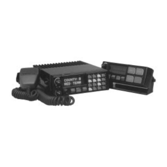
INTRODUCTION This manual describes how to use the EDACS ORION Mobile Radio. The ORION is a synthesized, microprocessor-based, high performance mobile FM radio providing reliable two-way communications in both the Enhanced Digital Access Communications System (EDACS) trunking environment and conventional communication systems. - Page 7 Figure 1 - EDACS ORION Mobile Radio SYSTEM Model Front Panel Figure 2 - EDACS ORION Mobile Radio SCAN Model Front Panel...
-
Page 8: Controls
CONTROLS This section describes the buttons, keys and rotary knobs used to control the Orion Scan and System Model radios. All functions and controls of the Scan radio operate the same as the corresponding functions and controls on the System radio. The Scan radio is equipped with a 4-button keypad and the System radio is equipped with a 16-button keypad. -
Page 9: Ramp Control
RAMP CONTROL The primary function of this rocker type button is to scroll through the System list or the Group/Channel list depending upon programming. The secondary function is to increment or decrement items within a list (phone list for example). Press to scroll in increasing order and press scroll in decreasing order. -
Page 10: Keypad
Figure 3 - ORION System Model Keypad Figure 4 - ORION Scan Model Keypad KEYPAD The keypad is similar to a telephone keypad but with four (4) additional but- tons on the side for a total of 16 keys. In addition to numbers (1-9, *, 0 and #), which is a secondary function, most of the keys have or can be pro- grammed to have a primary function. -
Page 11: Standard Keycap Configuration
Standard Keycap Configuration The Standard keycap package for the System radio includes five (5) labeled keycaps (MODE, HOME, CHN, AUX1 and AUX2) and six (6) blank key- caps, which can be placed on any of the five key locations (numbers 3-6 and 9) shown in Figure 5. - Page 12 This key is used to enter the System select mode. This key is used to enter the Group select mode. This key function is used to toggle a PC programmable fea- ture On and Off. Primary function - accesses the menu list. This is a list of additional features that are not available directly from the keypad.
-
Page 13: Primary Functions (Quick Access)
Toggles the external alarm On/Off. The external alarm is used to indicate the radio is receiving an Individual Call. Press the key once to enable external alarm and press again to disable external alarm. SG1-SG5 Corresponds to five (5) pre-programmed System/Groups. Pressing a key programmed for SG1 would switch the radio to the pre-programmed System/Group 1. -
Page 14: Display
tions. This provides quick access to the primary functions of the keypad. This is a programmable feature of the button only. Careful considera- tion should be given to possible operational conflicts before enabling this feature. Several keys on the Scan version have sel secondary function. The is the SELECT secondary function with the key remaining the same for the secondary function. - Page 15 Message Name Description QUEUED Call Queued Trunked mode only. Indicates the system has placed the call in a request queue. SYS BUSY System Busy Trunked mode only. Indicates the system is busy, no channels are currently available, the queue is full or an individual call is being attempted to a radio that is currently transmitting.
- Page 16 Message Name Description PA ON Public Address On Indicates that the public address function of the radio is enabled. PA OFF Public Address Off Momentary (2 seconds) indicates that public address function of the radio was disabled. ALRM ON External Alarm Enabled Indicates that the external alarm function of the radio is enabled.
- Page 17 Message Name Description MENU Displayed when the menu key is pressed and remains displayed in line 1 until one chooses a menu item. SYS=1-64 System = 1 - 64 This is the system number for the current base station of the system displayed in line 1. It is displayed in line 2 of the display.
- Page 18 Message Name Description DUAL Dual Control Indicate that the Control Unit is the idle Mode controller in a dual contro with System. Displayed on line 1. N0 ENTRY This indicates that there is no data stored in one of the programmable items in either the phone list or individual call list.
-
Page 19: Alert Tones
Message Name Description KEY LOAD This is displayed in line 1 of the display when the encryption key loader is connected. KEY ZERO This is displayed on line 2 of the display when the operator depresses the reset and option buttons simultaneously for approximately two seconds. -
Page 20: Call Originate
CALL ORIGINATE A short mid-pitched alert tone sounds after keying the radio (Push-To-Talk button is pressed). This indicates the radio has been assigned a working channel or that the radio is transmitting on a conventional channel and voice communication may begin immediately. In conventional mode, this tone may be delayed after the PTT button is pressed due to GE-STAR signaling (if enabled through programming). -
Page 21: Carrier Control Timer
CARRIER CONTROL TIMER If the programmed time for continuous transmission is exceeded, five short high-pitched warning tones followed by a long low-pitched tone will be heard. The transmitter will shut down shortly after hearing the alert, inter- rupting communications. Release and re-key the PTT button to maintain communications. -
Page 22: Selection Mode Rules
SELECTION MODE RULES Many operations require selection from a list such as system, group or phone number. This selection process is handled in the same manner for all lists. The RAMP control , 0-9, *, #, the button and the button are used during the selection process. -
Page 23: Direct Access
A new system from the list is selected by using the RAMP control or by directly entering the system number with the numeric keys. The RAMP control scrolls through the list in increasing and decreas- ing order. In the previous example, pressing the RAMP control selects the EAST system as shown in the next display. -
Page 24: Menu
mal receive mode display. Continuing with the selection process will return the display to the same point in the selection process if the selection mode time out has not yet expired. Any press of the PTT button during the selec- tion mode process will initiate transmission and exit the selection mode. - Page 25 PRESS: The RAMP control until the display shows: M E N U B C K L G H T PRESS: The backlight menu item is activated and the display will be similar to the following: B C K = X X X Y Y Y Y Y Y Y Y Line one shows the active menu item and its current parameter setting (XXX).
- Page 26 TABLE 1 - MENU ITEM INFORMATION FEATURE DISPLAY PARAMETER COMMENT SETTINGS Allows access to the PHONE CALL Menu item: PHN CALL Phone Call Feature. Once selected: See Telephone Interconnect Call Section Individual Call Menu Item: Allows access to the Individual Call (Trunked Systems IND CALL Only)
-
Page 27: System/Group/Channel Selection
SYSTEM/GROUP/CHANNEL SELECTION In the following description of SYSTEM/GROUP/CHANNEL SELEC- TION, the term group is used for both group and channel. The ORION SYSTEM/GROUP/CHANNEL knob and the RAMP control pair are programmable for maximum flexibility. If the SYS- TEM/GROUP/CHANNEL knob is assigned to select groups, then the RAMP control is assigned to select systems. -
Page 28: Group And Channel Selection
Group And Channel Selection Several methods, some of which depend on programming, can be used to se- lect a new group or channel. These procedures are presumed to be starting from the normal receive display. METHOD 1 If group selection is programmed to the SYSTEM/GROUP/ CHANNEL knob, select a group by turning the SYSTEM/ GROUP/CHANNEL knob to the desired group. -
Page 29: Sending A Call
4. Select the desired system and group. The display indicates the current system and group names. 5. The radio is now ready to receive calls. 6. When the radio receives a group call, it unmutes on the assigned working channel and BSY indicator comes on. Line one shows GR followed by the logical ID number (if received) of the unit sending the message, or the associated name if the ID number is found in the individual call list. -
Page 30: Emergency Operation
Operation during conventional failsoft will be the same as operation on a conventional system, except that it will not be possible to select a communi- cations channel, or use emergency and special call. When trunking is re- stored, the radio will automatically be returned to normal operation. NOTE Emergency and Special Call are not operational during conventional failsoft. -
Page 31: System Scan Operation
4. Release PTT when the transmission is complete and listen for a reply. 5. The emergency can be cleared by pressing and holding the button followed by pressing the button then releasing both buttons. System Scan Operation Wide Area System Scan The ORION radio may be programmed for wide area system scan operation for multi-site applications. - Page 32 TX Select - the group the radio will transmit on while scanning. The radio is programmed to transmit on either the scanned group or the selected group. Scan List (privileges) - this feature allows or prohibits scan list changes by the user.
- Page 33 already set and a new group is assigned as Priority 1 or Priority 2, the previously assigned group will change to non-priority scanning. Deleting Groups From A Scan List 1. With scan operation turned off, select the desired group to delete from the selected trunked system’s group scan list.
-
Page 34: Individual Calls
• Pressing when scan is on will cause the radio to recall the < scanned group that was last received. This group is recalled for a period equal to the scan hang time. Priority Group Scanning When scan is enabled and the Priority 1 and Priority 2 groups have been identified, the radio will listen to calls on those groups and the selected group. - Page 35 If a response is made to the call prior to the programmed call-back time-out, the call will automatically be directed to the originating unit. If a response is not made before the call-back time-out, the radio will return to normal re- ceive mode, but * WHC * will be displayed.
-
Page 36: Telephone Interconnect Calls
TELEPHONE INTERCONNECT CALLS Receiving A Telephone Interconnect Call (Trunked Mode Only) Receiving a telephone interconnect call is identical to receiving an individ- ual call. See the DTMF Overdial Operation section if access to services re- quiring "over-dial" is needed. Overdial operations are available for any special call whether it is an individual call or a telephone interconnect call. -
Page 37: Dtmf Overdial/Conventional Mode Telephone Interconnect
4. To terminate the call, momentarily press the button. NOTE The ORION radio is capable of simplex (one-way) conversation only. The caller can only hear the radio if the PTT button is pressed (the ra- dio is transmitting) and the caller can only be heard when PTT is re- leased (the radio is receiving). -
Page 38: Programmable Entries
phone list or to directly enter the overdial digits. Press PTT to send the overdial sequence once. If the number needs to be transmitted again it must be selected or entered again (this prevents unwanted numbers from being sent the next time the PTT button is pressed during the call). -
Page 39: Conventional Mode Operation
CONVENTIONAL MODE OPERATION The radio functions in the conventional mode when using conventional com- munications channels (non-trunked). Each channel consists of a preset fre- quency pair for transmit and receive during repeater operation, or a single frequency for both transmit and receive during talk-around (no repeater) op- eration. -
Page 40: Emergency Operation
serve the unlit BSY indicator. If the Channel Busy Lockout feature is programmed for the selected channel, the radio will not transmit when the channel is busy. 3. Press and hold the PTT button. The TX indicator will turn on and a short beep sounds (if programmed) indicating that communication can begin. -
Page 41: Scanning Conventional Channels
the emergency signaling and then change back to the se- lected channel. METHOD 4: Same as METHOD 3 but the radio will lock on to the pre- programmed emergency system and channel. Any attempts to change the system or channel will be disabled. The emergency state can be cleared by turning the radio off and then back Scanning Conventional Channels Channels which have been previously added to the scan list on a per system... -
Page 42: Turning Scan On
ning and 1 is displayed on line one. If the priority-one or priority-two channels are already set and a new channel is then assigned as the prior- ity-one or priority-two channel, the previously assigned priority channel will change to non-priority scanning. The priority setting selection se- quence is set and stops at priority-one therefore the channel must be de- leted from the scan list by pressing before the channel is set to a... -
Page 43: Turning Scan Off
• The radio will continue scanning if a new channel is selected when scan is on. • Pressing the PTT button when scan is on will cause the radio to transmit on the displayed channel or to the currently selected channel depending on programming. -
Page 44: Siren/Light Operation
2. The display will show SQLCH=xx, where "xx" is the value between 1 and 16. 3. Use the RAMP control to scroll through the values. Then press the key to save the new value after the display time-out (2 sec- onds). -
Page 45: Aegis And Voice Guard Operation
mable between from .5-127.5 seconds. During the time-out window the re- spective key indicator will be on. When the timer expires, the activity will be terminated and the indicator will turn off. If an additional time-out key (pro- grammed for ADDITIVE) is pressed during the time-out window, then the time-out window is reset and both activities will terminate at the same time. -
Page 46: Clear Modes
NOTE Conventional Aegis or encrypted channels require Channel Guard on the channel to operate correctly. CLEAR MODES Aegis clear and Voice Guard clear modes are identical voice modes in which the radio transmits and receives only clear (analog) voice signals. These ana- log signals are non-digitized and non-encrypted. -
Page 47: Dtmf
DTMF The overdial and hot keypad features for transmitting DTMF tones are not available while in the Aegis Digital Mode. ERROR Messages If either of the following error messages are displayed, the radio was either programmed incorrectly or needs servicing: DSP ERR DSP ERR (Power... -
Page 48: Transferring Keys Into The Radio
be programmed for keys 1-7. Up to 8 banks of 7 keys can be stored for Aegis (DES and VGE) systems. DES radios require a DES Keyloader (Option V4025 with software version 3.n or later). VGE radios require a VGE Keyloader (Option V4028 with soft- ware version 2.n or later). -
Page 49: Displaying The Currently Used Cryptographic Key Number
8. Disconnect the cable from the control unit’s microphone connector. Press (Scan Model) or (System Model) button to exit the key- load operation. The radio will change to the selected group or channel as indicated in the display. Displaying The Currently Used Cryptographic Key Number To display the cryptographic key currently in use for either the system en- cryption key (for special call such as individual, phone, all, agency or fleet) -
Page 50: Private Operation
PRIVATE OPERATION Receiving An Encrypted Call When receiving, the radio automatically switches between clear or private operation. If the transmission being received is an encrypted transmission, it will be decrypted, the PVT keylight (System Model) or OPTION keylight (Scan Model) will flash, the receiver will unsquelch and the message will be heard in the speaker. -
Page 51: Scanned Group Calls
Scanned Group Calls Receiving a scanned group call is the same as receiving a selected group call. During the scan hang time, if the radio was programmed for autoselect, it will transmit back in the same mode it received the call. For example, if a clear group is entered in the scan list, it will only receive clear calls. -
Page 52: Displays
selected transparently by the operator through normal usage of the radio. Data communications is not supported in the conventional mode. The mobile radios may be connected to Mobile Data Terminals (MDT) or to a host computer. Any RS-232 compatible device that supports the Radio Data Interface (RDI) protocol (Version 1.91 or greater) may be connected to the mobile radio. -
Page 53: Data On Operation
• Selecting the function using the button (pre-programmed). • Pressing the ND button (System Model Only) (pre-programmed). DATA ON OPERATION The data state is enabled by one of the following (depending on how it was disabled). "DATA ON" will be displayed top line of display for 2 seconds then the display returns to normal. -
Page 54: Data Lockout Mode
• PTT is pressed. • A group or system change. • Entering phone call mode • Entering individual call mode. • A new emergency assignment has been received. • PTT pressed in Public Address Mode. • An emergency declared or cleared. •... -
Page 55: Switching Control
tional modes. Only one control unit can control the mobile radio unit at a time. The control unit which controls the radio operation is called the active controller and the second unit is called the idle controller. SWITCHING CONTROL Control can be switched to the idle controller by pressing the push-to-talk (PTT) on the microphone associated with the idle controller. -
Page 56: Independent Mode Operation
Independent Mode Operation During Independent operation, the radio system operates as if there are two radio units each controlled by a separate control unit. Each control unit maintains its own System and Group settings which are restored when con- trol is switched. The idle controller will display DUAL on line one to indicate that it is idle. -
Page 57: Status/Message Operation
STATUS/MESSAGE OPERATION Status and message operation is possible with either the Scan or System ver- sion of the ORION radio unit. The following procedure is applicable for the System version. For operation with the Scan version the four primary key- caps must be reconfigured and pre-programmed for status/message opera- tion. -
Page 58: Edacs Conventional P1 Scan
To send a message, press the button then press one of the number but- tons (0-9) to select the pre-programmed message text. If no message text has been programmed for the selected number button, the radio will display NO ENTRY. A valid selection will permit the message text to appear in the dis- play for a pre-programmed time. -
Page 59: Changing Selected Radio
play and control. The control unit display is shared by the multiple radio units and, when selected, a radio can be controlled by the control unit. For multiple radio operation the control unit keypad must be pre-pro- grammed for a variety of multiple radio buttons such as radio selection and radio mute. -
Page 60: Audio Summed
Audio Summed When audio is summed, the audio from all radios will be available when- ever the radios receive a call. If two radios receive a call simultaneously both calls will be heard in the speaker. Audio First Come First Serve When audio is pre-programmed for first come first serve, the audio from the radio that receives a call first will be heard from the speaker for the duration of the call and hang time (if enabled). -
Page 61: Emergency Operation
that receives and acknowledges a regrouping instructions is successfully re- grouped. Pressing and holding the (Scan Model) or (System Model) button for 2.5 seconds toggles the user into and out of the dynamic regroup group- set. A double beep will sound for entry or exit. The display will indicate REGR_0x where "x"... -
Page 62: Keypad Remapping
KEYPAD REMAPPING If the keys have been remapped to provide new functions, please fill in the following for future reference. ORION System Model Keypad ORION Scan Model Keypad... -
Page 63: Operating Rules And Regulations
OPERATING RULES AND REGULATIONS Two way FM radio systems must be operated in accordance with the rules and regulations of the Federal Communications Commission (FCC). As an operator of two way radio equipment, the user must be thoroughly familiar with the rules that apply to the intended type of radio operation. Following these rules will help to eliminate confusion, assure the most efficient use of existing radio channels, and result in a smoothly functioning radio network. -
Page 64: Glossary
GLOSSARY Agency An agency is composed of multiple fleets. Units can be programmed to initiate agency calls to access multiple fleets. (Trunked Mode Only) Base/Unit A programmed option used in some fleets so units Operation can only hear and talk to a base dispatch unit, not to other mobiles or personals in the group. - Page 65 Group Or A group of users share the same program group iden- Subfleet tification number in their mobile and personal radios. All units in the same group will receive a dispatch call placed by any one unit in the group. (Trunked Mode only).
- Page 66 Talk-around Also referred to as “direct mode”, talk-around pro- Mode vides a direct unit-to-unit short range communica- tions link. It is intended to maintain communications outside of the main system coverage area. Telephone This feature allows the user to initiate or receive tele- Inter- phone calls through the radio if the system is config- Connect...
-
Page 67: Operator's Radio Setup
OPERATOR’S RADIO SETUP RADIO TYPE: FREQUENCY BAND: OPERATOR’S NAME: EMERGENCY GROUP: SYSTEM SYSTEM TRK/CNV GRP/CHN GRP/CHN NUMBER NAME NUMBER NAME... - Page 68 SYSTEM SYSTEM TRK/CNV GRP/CHN GRP/CHN NUMBER NAME NUMBER NAME...
- Page 69 SYSTEM SYSTEM TRK/CNV GRP/CHN GRP/CHN NUMBER NAME NUMBER NAME...
- Page 70 SYSTEM SYSTEM TRK/CNV GRP/CHN GRP/CHN NUMBER NAME NUMBER NAME...
- Page 71 WARRANTY Ericsson Inc. (hereinafter "Seller") warrants to the original purchaser for use (hereinafter "Buyer") that Equipment manufactured by Seller shall be free from defects in material, workmanship and title, and shall conform to its published specifications. With respect to any Equipment not manufactured by Seller (except for integral parts of Seller’s Equipment to which the warranties set forth above shall apply).
- Page 72 (particularly if a glass mount antenna is used.). Moving a few yards in another direction or moving to a higher elevation may also improve communications. Ericsson Inc. Private Radio Systems Mountain View Road...