Table of Contents
Advertisement
Quick Links
Advertisement
Table of Contents

Summary of Contents for Toyota A442F
- Page 4 IN-1 INTRODUCTION HOW TO USE THIS MANUAL I N - 2 GENERAL REPAIR INSTRUCTIONS I N - 5 ABBREVIATIONS USED IN THIS MANUAL I N - 7 STANDARD BOLT TORQUE SPECIFICATIONS I N - 8...
- Page 5 IN-2 INTRODUCTION - HOW TO USE THIS MANUAL HOW TO USE THIS MANUAL INOO2-OC To assist you in finding your way through the manual, the Section Title and major heading are given at the top of every page. PREPARATION Preparation lists the SST (Special Service Tools), recommended tools, equipment, lubricant and SSM (Special Service Materials) which should be prepared before beginning the operation and explains the purpose of each one.
-
Page 6: Specifications
IN-3 INTRODUCTION - HOW TO USE THIS MANUAL The procedures are presented in a step —by—step format: • The illustration shows what to do and where to do it. • The task heading tells what to do. • The detailed text tells how to perform the task and gives other information such as specifications and warnings. - Page 7 IN-4 INTRODUCTION - HOW TO USE THIS MANUAL CAUTIONS, NOTICES, HINTS: • CAUTIONS are presented in bold type, and indicate there is a possibility of injury to you or other people. • NOTICES are also presented in bold type, and indicate the possibility of damage to the components being repaired.
- Page 8 IN-5 INTRODUCTION - GENERAL REPAIR INSTRUCTIONS GENERAL REPAIR INSTRUCTIONS Use fender, seat and floor covers to keep the vehicle clean and prevent damage. During disassembly, keep parts in the appropriate order to facilitate reassembly. Observe the following: Before performing electrical work, disconnect the negative cable from the battery terminal.
- Page 9 INTRODUCTION - GENERAL REPAIR INSTRUCTIONS When reusing precoated parts, clean off the old adhesive and dry with compressed air. Then apply the specified seal lock adhesive to the bolt, nut or threads. Precoated parts are indicated in the component illustrations by the symbol.
- Page 10 IN-7 INTRODUCTION - ABBREVIATIONS USED IN THIS MANUAL ABBREVIATIONS USED IN THIS MANUAL Automatic Transaxle Fluid Overdrive Brake 2nd Brake 1 st and Reverse Brake Overdrive Direct Clutch Front Clutch Rear Clutch Disc Except Flange Overdrive One—way Clutch No.2 One-way Clutch Multipurpose Overdrive Plate...
- Page 11 IN-8 INTRODUCTION - STANDARD BOLT TORQUE SPECIFICATIONS STANDARD BOLT TORQUE SPECIFICATIONS HOW TO DETERMINE BOLT STRENGTH Hexagon Stud bolt head bolt No mark No mark Hexagon flange bolt No mark Grooved w/ washer hexagon bolt Hexagon head bolt protruding lines Hexagon flange bolt Welded bolt...
- Page 12 IN-9 INTRODUCTION - STANDARD BOLT TORQUE SPECIFICATIONS SPECIFIED TORQUE FOR STANDARD BOLTS...
- Page 13 MEMO...
- Page 14 AT-1 AUTOMATIC TRANSMISSION DESCRIPTION A T - 2 OPERATION A T - PREPARATION A T - 10 COMPONENT PARTS REMOVAL A T - 13 OIL PUMP A T - 3 3 OVERDRIVE UNIT A T - 38 FRONT CLUTCH A T - 5 2 REAR CLUTCH A T - 5 9 SECOND BRAKE...
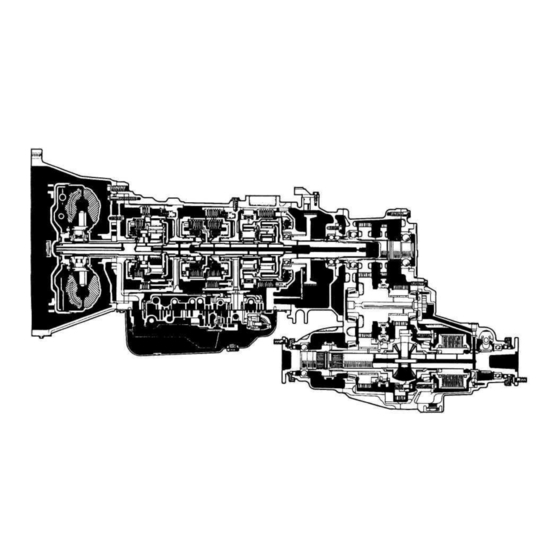
- Page 15 AUTOMATIC TRANSMISSION - DESCRIPTION DESCRIPTION GENERAL The new A442F automatic transmission is a 4 —speed Electronic Controlled Automatic Trans- mission and has following features; Electronic control provides shift and lock —up points most appropriate for the power charac- teristics of each engine and improves shift response.
- Page 16 AT-3 AUTOMATIC TRANSMISSION - DESCRIPTION GENERAL SPECIFICATIONS Type of Transmission A442F Type of Engine 1FZ-FE 1HD-T 2.0: 1 Torque Converter Stall Torque Ratio 1.8: 1 Lock —up Mechanism Equipped 2.950 Gear Ratio 1 st Gear 2nd Gear 1.530 1.000 3rd Gear O/D Gear 0.765...
- Page 17 AT-4 AUTOMATIC TRANSMISSION - OPERATION OPERATION OPERATING CONDITIONS...
- Page 18 AT-5 AUTOMATIC TRANSMISSION - OPERATION FUNCTION OF COMPONENTS...
- Page 19 AT-6 AUTOMATIC TRANSMISSION - OPERATION The condition of operation for each gear position are shown on the following illustration:...
- Page 20 AT-7 AUTOMATIC TRANSMISSION - OPERATION...
- Page 21 AT-8 AUTOMATIC TRANSMISSION - OPERATION HYDRAULIC CONTROL SYSTEM The hydraulic control system is composed of the oil pump, the valve body, the solenoid valve, the accumulators, the clutches and brakes, as well as the fluid passages which connect all of these components.
- Page 22 AT-9 AUTOMATIC TRANSMISSION - OPERATION WARNING AND INDICATOR LIGHTS A.T FLUID TEMPERATURE WARNING SYSTEM The ECT ECU detects the transmission fluid temperature by means of a fluid temperature sensor fitted to the union. The transmission fluid may become extremely hot when the vehicle is under and extreme load, as when driving on sand or climbing uphill.
- Page 23 AT-10 AUTOMATIC TRANSMISSION - PREPARATION PREPARATION SST (SPECIAL SERVICE TOOLS)
- Page 24 AT-11 AUTOMATIC TRANSMISSION - PREPARATION RECOMMENDED TOOL EQUIPMENT...
- Page 25 AT-12 AUTOMATIC TRANSMISSION - PREPARATION LUBRICANT SSM (SPECIAL SERVICE MATERIALS)
- Page 26 AT-13 AUTOMATIC TRANSMISSION - COMPONENT PARTS REMOVAL COMPONENT PARTS REMOVAL COMPONENTS...
- Page 27 AT-14 AUTOMATIC TRANSMISSION - COMPONENT PARTS REMOVAL...
- Page 28 AT-15 AUTOMATIC TRANSMISSION - COMPONENT PARTS REMOVAL...
- Page 29 AT-16 AUTOMATIC TRANSMISSION - COMPONENT PARTS REMOVAL SEPARATE BASIC SUBASSEMBLY REMOVE TRANSMISSION WIRING Disconnect the connectors, and remove the trans- mission wiring. REMOVE BREATHER LUG AND HOSE Using two screwdrivers, pry out the breather plug. Remove the 0 —ring from the breather plug. REMOVE CONTROL SHAFT LEVER Remove the two nuts and the lever.
- Page 30 AT-17 AUTOMATIC TRANSMISSION - COMPONENT PARTS REMOVAL REMOVE TRANSMISSION TEMPERATURE SENSOR Remove the sensor from front union. Remove the 0 —ring from the sensor. REMOVE OIL COOLER UNIONS Remove the two unions. Remove the 0 —rings from the both unions. REMOVE TRANSMISSION HOUSING Remove the throttle cable clamp bolt.
- Page 31 AT-18 AUTOMATIC TRANSMISSION - COMPONENT PARTS REMOVAL 11. REMOVE OIL PAN NOTICE: Do not turn the transmission over as this will contaminate the valve body with any foreign matter at the bottom. Remove the twenty bolts. (b) Tap in the blade SST between the transmission and oil pan, cut off applied sealer.
- Page 32 AT-19 AUTOMATIC TRANSMISSION - COMPONENT PARTS REMOVAL Disconnect the four connectors from the solenoids. Disconnect the throttle cable from the cam and remove the valve body. 15. REMOVE O / D CASE AND CENTER SUPPORT APPLY GASKETS Remove the four apply gaskets. 16.
- Page 33 AT-20 AUTOMATIC TRANSMISSION - COMPONENT PARTS REMOVAL 18. REMOVE C Bo B ACCUMULATOR PISTONS AND SPRINGS Remove the C accumulator piston and spring by applying compressed air to the oil hole. Remove the B accumulator piston together with the accumulator piston by applying compressed air to the oil hole.
- Page 34 AT-21 AUTOMATIC TRANSMISSION - COMPONENT PARTS REMOVAL 2 1 . REMOVE OIL PUMP Remove the eleven bolts holding the oil pump to the transmission case. Remove the oil pump and gasket. Remove the 0 —ring from the oil pump. Remove the oil pump gasket. Remove the race and thrust bearing from the 0 / D direct clutch drum or oil pump.
- Page 35 AT-22 AUTOMATIC TRANSMISSION - COMPONENT PARTS REMOVAL Remove the bearing from the O/D planetary gear or ring gear flange. 23. REMOVE OVERDRIVE PLANETARY RING GEAR ASSEMBLY Remove the ring gear assembly from the O/D case. Remove the thrust bearing and race from the O/D case or ring gear flange.
- Page 36 AT-23 AUTOMATIC TRANSMISSION - COMPONENT PARTS REMOVAL Push the O/D case toward the rear of the transmis- sion by applying a force of 49 — 98 N (5 — 10 kgf, 11.0 - 2 2 . 0 Ibf) Using SST and dial indicator, measure the thrust cle- arance of the input shaft.
- Page 37 AT-24 AUTOMATIC TRANSMISSION - COMPONENT PARTS REMOVAL 26. REMOVE FRONT CLUTCH ASSEMBLY Place SST, on the installation surface of the oil pump. SST 09350-36010(09350-06090) Using calipers, measure the distance between the tops of SST and the clutch drum for assembly. Remove the front clutch assembly.
- Page 38 AT-25 AUTOMATIC TRANSMISSION - COMPONENT PARTS REMOVAL Push the center support toward the rear of the tra- nsmission by applying a force of 49 — 98 N (5 — 10 kgf, 11.0 — 22.0 Ibf), then pull with the same amount of force.
- Page 39 AT-26 AUTOMATIC TRANSMISSION - COMPONENT PARTS REMOVAL Maximum thrust clearance: 0.90 mm (0.0354 in.) Remove the thrust washer from the center support. 29. REMOVE SPEEDSENSOR 30. REMOVE TRANSFER ADAPTOR AND OUTPUT SHAFT REAR BEARING Remove the five bolts and the tear bearing retainer. Using snap ring pliers, remove the snap ring.
- Page 40 AT-27 AUTOMATIC TRANSMISSION - COMPONENT PARTS REMOVAL remove the ten bolts and the adaptor. Remove the gasket. 3 1 . REMOVE OUTPUT SHAFT SPACER Using snap ring pliers, remove the snap ring. Remove the output shaft spacer. 32. REMOVE SPEED SENSOR ROTOR 33.
- Page 41 AT-28 AUTOMATIC TRANSMISSION - COMPONENT PARTS REMOVAL Using a screwdriver, remove the snap ring. Remove the planetary gears, one —way clutch and output shaft assembly. 34. CHECK PISTON STROKE OF FIRST AND REVERSE BRAKE PISTON Using SST and a dial indicator, measure the piston stroke by applying and releasing the compressed air 3 9 2 - 7 8 5 kPa ( 4 - 8 kgf/cm , 5 7 - 1 1 4 psi) sa shown.
- Page 42 AT-29 AUTOMATIC TRANSMISSION - COMPONENT PARTS REMOVAL Remove the flange, six plates and cushion plate. Set SST on the spring retainer, and compress the return spring. SST 09350-36010(09350-06030) Using snap ring pliers, remove the snap ring. Remove the piston return spring. Hold first and reverse brake piston with hand, remove first and reverse brake piston by applying compressed air into the oil hole of the transmission case.
- Page 43 AT-30 AUTOMATIC TRANSMISSION - COMPONENT PARTS REMOVAL 36. REMOVE C, ACCUMULATOR PISTON AND SPRING Remove the four bolts, front clutch accumulator cover, two gaskets and plate. Remove the accumulator piston and spring by apply- ing compressed air to the oil hole. Remove the 0 —rings from accumulator piston.
- Page 44 AT-31 AUTOMATIC TRANSMISSION - COMPONENT PARTS REMOVAL Pull the manual valve lever shaft out through the case, remove the manual valve lever, parking lock rod as- sembly, the two plate washers and wave washer. Disconnect the parking lock rod from the manual valve lever.
-
Page 45: General Notes
AT-32 AUTOMATIC TRANSMISSION - COMPONENT PARTS REMOVAL GENERAL NOTES The instructions here are organized so that you work on only one component group at a time. This will help avoid confusion from similar —looking parts of different subassemblies being on your workbench at the same time. - Page 46 AT-33 AUTOMATIC TRANSMISSION - OIL PUMP OIL PUMP COMPONENTS COMPONENTS DISASSEMBLY USE TORQUE CONVERTER AS WORK STAND REMOVE OIL SEAL RINGS remove the two oil seal rings.
- Page 47 AT-34 AUTOMATIC TRANSMISSION - OIL PUMP REMOVE CHECK BALL Using SST, compress the spring and remove the spring seat. SST 09350-36010(09350-06100) Remove the spring and check ball. REMOVE EIGHT BOLTS AND PUMP COVER REMOVE OIL PUMP DRIVE AND DRIVEN GEARS OIL PUMP INSPECTION INSPECT BUSHING OF OIL PUMP BODY Using a dial indicator, measure the inside diameter.
- Page 48 AT-35 AUTOMATIC TRANSMISSION - OIL PUMP Rear bushing maximum inside diameter: 26.57 mm (1.0461 in.) If the inside diameter is greater than the maximum, replace the pump cover. INSPECT BODY CLEARANCE OF DRIVEN GEAR Push the driven gear to one side of the body. Using a feeler gauge, measure the clearance between the driven gear and body.
- Page 49 AT-36 AUTOMATIC TRANSMISSION - OIL PUMP IF NECESSARY, REPLACE OIL SEAL Using a screwdriver, pry off the oil seal. (b) Using SST, tap in a new oil seal. The oil sel end should be with the outer edge of the pump body. SST 09350-36010(09350-06040) Apply MP grease to the oil seal lip.
- Page 50 AT-37 AUTOMATIC TRANSMISSION - OIL PUMP INSTALL CHECK BALL Install the check ball and spring. Using SST, compress the spring and install the spring seat. SST 09350-36010(09350-06110) INSTALL OIL SEAL RINGS Coat the two oil seal rings with ATF. Contract the oil seal rings, and install them onto the stator shaft.
- Page 51 AT-38 AUTOMATIC TRANSMISSION - OVERDRIVE UNIT OVERDRIVE UNIT COMPONENTS...
- Page 52 AT-39 AUTOMATIC TRANSMISSION - OVERDRIVE UNIT OVERDRIVE GEAR UNIT DISASSEMBLY CHECK OPERATION OF ONE-WAY CLUTCH Hold the O/D direct clutch drum and turn the input shaft. The input shaft should turn freely clockwise and should lockcounterclockwise. REMOVE OVERDRIVE DIRECT CLUTCH ASSEMBLY FROM OVERDRIVE PLANETARY GEAR CHECK PISTON STROKE OF OVERDRIVE DIRECT CLUTCH...
- Page 53 AT-40 AUTOMATIC TRANSMISSION - OVERDRIVE UNIT Remove the flange, three discs and three plates. REMOVE PISTON RETURN SPRING Place SST on the spring seat, and compress the return spring with a shop press. SST 09350-3601 0(09350-0601 0) Using snap ring pliers, remove the snap ring. Remove the spring seat and twenty —...
- Page 54 AT-41 AUTOMATIC TRANSMISSION - OVERDRIVE UNIT Remove the ring gear flange. REMOVE O N E - W A Y CLUTCH FROM OVERDRIVE PLANETARY GEAR Using small screwdriver, remove the snap ring. Remove the No.4 thrust washer. Remove the one —way clutch together with the outer race.
- Page 55 AT-42 AUTOMATIC TRANSMISSION - OVERDRIVE UNIT Remove the two retainers and one —way clutch from the outer race. 10. REMOVE RING RETAINERS Using needle nose pliers, remove the three ring re- tainers from the oil holes of O/D case. 11. CHECK PISTON STROKE OF OVERDRIVE BRAKE Place the O/D case assembly onto the rear clutch assembly.
- Page 56 AT-43 AUTOMATIC TRANSMISSION - OVERDRIVE UNIT Remove the flange, three discs and three plates. 13. REMOVE PISTON RETURN SPRING Place SST on the spring seat, and compress the return spring with a shop press. SST 09350-36010(09350-06020) Using screwdriver, remove the snap ring. Remove the return spring.
- Page 57 AT-44 AUTOMATIC TRANSMISSION - OVERDRIVE UNIT OVERDRIVE UNIT INSPECTION INSPECT DISCS, PLATES AND FLANGE Check to see if the sliding surface of the disc, plate and flange are worn or burnt. If necessary, replace them. HINT: • If the lining of the disc is peeling off or discolored, or even if parts of the printed numbers are def- aced, replace all discs.
- Page 58 AT-45 AUTOMATIC TRANSMISSION - OVERDRIVE UNIT INSPECT PLANETARY PINION GEAR THRUST CLEARANCE Using a feeler gauge, measure the clearance between the pinions and carrier. Standard clearance: 0.20-0.59 mm (0.0079-0.0232 in.) Maximum clearance: 0.80 mm (0.0315 in.) If the thrust clearance is grater than maximum, re- place the planetary gear.
- Page 59 AT-46 AUTOMATIC TRANSMISSION - OVERDRIVE UNIT Install the No.4 thrust washer. Using a screwdriver, install the snap ring. INSTALL RING GEAR FLANGE TO OVERDRIVE PLANETARY RING GEAR Install the gear flange as shown. Using a screwdriver, install the snap ring. INSTALL OIL SEAL RING Coat the oil seal ring with ATF, and install it to the ring gear flange.
- Page 60 AT-47 AUTOMATIC TRANSMISSION - OVERDRIVE UNIT INSTALL OVERDRIVE DIRECT CLUTCH PISTON Coat new 0 —rings with ATF, and install them on the clutch piston. Push in the clutch piston into the clutch drum with both hands. NOTICE: Be careful not to damage the 0 —rings. INSTALL PISTON RETURN SPRING Place the piston return spring on the clutch piston.
- Page 61 AT-48 AUTOMATIC TRANSMISSION - OVERDRIVE UNIT Using a screwdriver, install the snap ring. HINT: Be sure the end gap of the snap ring is not aligned with the cutout portion of the clutch drum. CHECK PISTON STROKE OF OVERDRIVE DIRECT CLUTCH Place the oil pump onto the torque converter, and then place the 0 / D direct clutch assembly onto the oil...
- Page 62 AT-49 AUTOMATIC TRANSMISSION - OVERDRIVE UNIT 10. INSTALL OIL SEAL RINGS Coat the two oil seal rings with ATF. Contract the oil seals, and install them onto the O/D case. NOTICE: Do not spread the ring ends more than neces- sary.
- Page 63 AT-50 AUTOMATIC TRANSMISSION - OVERDRIVE UNIT 13. INSTALL PLATES, DISCS AND FLANGE Install the three plates and three discs in order: P = Plate D = Disc P-D-P-D-P-D (b) Install the flange, facing the rounded edge upward. Using a screwdriver, install the snap ring. HINT: Be sure the end gap of the snap ring is not aligned with the cutout portion of the O/D case.
- Page 64 AT-51 AUTOMATIC TRANSMISSION - OVERDRIVE UNIT 15. INSTALL RING RETAINERS Using needle nose pliers, install the three ring retain- ers into the oil holes of the O/D case.
- Page 65 AT-52 AUTOMATIC TRANSMISSION - FRONT CLUTCH FRONT CLUTCH COMPONENTS FRONT CLUTCH DISASSEMBLY PLACE FRONT CLUTCH ASSEMBLY ONTO OVER- DRIVE CASE ASSEMBLY REMOVE REAR AND FRONT CLUTCH HUBS Using a screwdriver, remove the snap ring.
- Page 66 AT-53 AUTOMATIC TRANSMISSION - FRONT CLUTCH Remove the rear clutch hub. Remove the front clutch hub. Remove the race and thrust bearing. CHECK PISTON STROKE OF FRONT CLUTCH Install SST to a dial indicator. SST 09350-36010(09350-06110) Place the assembled SST and a dial indicator on the clutch piston.
- Page 67 AT-54 AUTOMATIC TRANSMISSION - FRONT CLUTCH REMOVE DISCS, PLATES AND CUSHION PLATE (1FZ-FE Engine) Remove the six discs, six plates and cushion plate. ( 1 H D - T Engine) Remove the seven discs, seven plates and cushion plate. REMOVE PISTON RETURN SPRINGS Place SST on the spring seat, and compress the return springs with a shop press.
- Page 68 AT-55 AUTOMATIC TRANSMISSION - FRONT CLUTCH FRONT CLUTCH INSPECTION INSPECT DISCS. PLATES AND CUSHION PLATE Check to see if the sliding surface of the disc, plate and cushion plate are worn or burnt. If necessary, replace all discs. HINT: • If the lining of the disc is peeling off or discolored, or even if parts of the printed numbers are def- aced, replace all discs.
- Page 69 AT-56 AUTOMATIC TRANSMISSION - FRONT CLUTCH INSTALL FRONT CLUTCH PISTON Coat new two 0 —rings with ATF, and install them on the clutch piston. Push in the clutch piston into the clutch drum by both hands. NOTICE: Be careful not to damage the O —rings. INSTALL PISTON RETURN SPRINGS Install the piston return spring.
- Page 70 AT-57 AUTOMATIC TRANSMISSION - FRONT CLUTCH ( 1 H D - T Engine) Install the seven plates and seven discs in order: P = Plate D = Disk P-D-P-D-P-D-P-D-P-D-P-D-P-D CHECK PISTON STROKE OF FRONT CLUTCH Install SST to a dial indicator. SST 09350-3601 0(09350-0611 0) Place the assembled SST and a dial indicator on the clutch piston.
- Page 71 AT-58 AUTOMATIC TRANSMISSION - FRONT CLUTCH (b) Install the front clutch hub into the clutch drum. HINT: Mesh the spline of the front clutch hub with the flukes of the discs by rotating the front clutch hub clockwise or counterclockwise. (c) Install the rear clutch hub onto the clutch drum.
- Page 72 AT-59 AUTOMATIC TRANSMISSION - REAR CLUTCH REAR CLUTCH COMPONENTS REAR CLUTCH DISASSEMBLY CHECK PISTON STROKE OF REAR CLUTCH Place the center support assembly on wooden blocks. HINT: Provide clearance so that the sun gear does not touch the rear clutch drum. Place the rear clutch assembly into the center support assembly.
- Page 73 AT-60 AUTOMATIC TRANSMISSION - REAR CLUTCH REMOVE FLANGE, DISCS AND PLATES Using a screwdriver, remove the snap ring. Remove the flange, five discs and five plates. REMOVE PISTON RETURN SPRINGS Place SST on the spring seat, and compress the return spring with a shop press.
- Page 74 AT-61 AUTOMATIC TRANSMISSION - REAR CLUTCH REAR CLUTCH INSPECTION INSPECT DISCS, PLATES AND FLANGE Check to see if the sliding surface of the disc, plate and flange are worn or burnt. If necessary, replace them. HINT: • If the lining of the disc is peeling off or discolored, or even if parts of the printed numbers are def- aced, replace all discs.
- Page 75 AT-62 AUTOMATIC TRANSMISSION - REAR CLUTCH (b) Place SST on the spring seat, and compress the return spring with a shop press. SST 09350-36010(09350-06010) Using snap ring pliers, install the snap ring. HINT: Be sure the end gap of the snap ring is not aligned with the spring retainer claw.
- Page 76 AT-63 AUTOMATIC TRANSMISSION - REAR CLUTCH (c) Using SST and a dial indicator, measure the piston stroke by applying and releasing the compressed air 392-785 kPa ( 4 - 8 kgf/cm . 5 7 - 1 1 4 psi) as shown. SST 09350-3601 0(09350-0611 0) Piston stroke: 2.00-2.20 mm (0.0790-0.0866 in.)
- Page 77 AT-64 AUTOMATIC TRANSMISSION - SECOND BRAKE SECOND BRAKE COMPONENTS SECOND BRAKE DISASSEMBLY REMOVE RING RETAINERS Using needle nose pliers, remove the three ring re- tainers from the oil holes of the center support. REMOVE FRONT PLANETARY SUN GEAR Using snap ring pliers, remove the snap ring.
- Page 78 AT-65 AUTOMATIC TRANSMISSION - SECOND BRAKE Remove the sun gear. CHECK PISTON STROKE OF SECOND BRAKE Using SST and a dial indicator, measure the piston stroke by applying and releasing the compressed air 3 9 2 - 7 8 5 kPa ( 4 - 8 kgf/cm , 5 7 - 1 1 4 psi) as shown.
- Page 79 AT-66 AUTOMATIC TRANSMISSION - SECOND BRAKE Remove the piston return spring. REMOVE SECOND BRAKE PISTON Place the return spring on the brake piston, and then place SST on the return spring. SST 09350-36010(09350-06020) Hold SST so it does not slant, and apply compressed air into the oil hole of the center support to remove the brake piston.
- Page 80 AT-67 AUTOMATIC TRANSMISSION - SECOND BRAKE INSPECT BUSHING OF CENTER SUPPORT Using a dial indicator, measure the inside diameter. Standard inside diameter: 35.000-35.025 mm (1.3780-1.3789) Maximum inside diameter: 35.08 mm (1.3811 in.) If the inside diameter is greater than the maximum, replace the center support.
- Page 81 AT-68 AUTOMATIC TRANSMISSION - SECOND BRAKE INSTALL PISTON RETURN SPRING Place the return spring on the brake piston. Place SST on the return spring, and compress the return spring with a shop press. SST 09350-36010(09350-06020) Using a screwdriver, install the snap ring. HINT: Be sure the end gap of the snap ring is not aligned with the cutout portion of the center support.
- Page 82 AT-69 AUTOMATIC TRANSMISSION - SECOND BRAKE CHECK PISTON STROKE OF SECOND BRAKE Using SST and a dial indicator, measure the piston stroke by applying and releasing the compressed air 3 9 2 - 7 8 5 kPa ( 4 - 8 kgf/cm , 5 7 - 1 1 4 psi).
- Page 83 AT-70 AUTOMATIC TRANSMISSION - FRONT AND REAR PLANETARY GEAR UNIT FRONT AND REAR PLANETARY GEAR UNIT COMPONENTS FRONT AND REAR PLANETARY GEAR UNIT DISASSEMBLY REMOVE REAR PLANETARY GEAR AND OUTPUT SHAFT ASSEMBLY Remove the rear planetary gear and output shaft as- sembly from the front planetary gear.
- Page 84 AT-71 AUTOMATIC TRANSMISSION - FRONT AND REAR PLANETARY GEAR UNIT CHECK OPERATION OF O N E - W A Y CLUTCH Hold the one —way clutch outer race and turn the front planetary gear. The front planetary gear should turn freely counterclockwise and should lock clock- wise.
- Page 85 AT-72 AUTOMATIC TRANSMISSION - FRONT AND REAR PLANETARY GEAR UNIT REMOVE REAR PLANETARY RING GEAR AND IN- TERMEDIATE SHAFT ASSEMBLY Remove the ring gear and intermediate shaft assem- bly from the rear planetary gear. Remove the thrust bearing from the front side of the ring gear flange.
- Page 86 AT-73 AUTOMATIC TRANSMISSION - FRONT AND REAR PLANETARY GEAR UNIT Remove the ring gear and flange assembly from the intermediate shaft. Using snap ring pliers, remove the snap ring from the front side of the intermediate shaft. 10. REMOVE REAR PLANETARY RING GEAR FLANGE Using a small screwdriver, remove the snap ring.
- Page 87 AT-74 AUTOMATIC TRANSMISSION - FRONT AND REAR PLANETARY GEAR UNIT 12. REMOVE NO.2 THRUST WASHER Remove the thrust washer from the rear planetary gear. NOTICE: Do not damage the No.2 thrust washer. 13. REMOVE O-RING Using a small screwdriver, remov the o —ring from the rear planetary gear.
- Page 88 AT-75 AUTOMATIC TRANSMISSION - FRONT AND REAR PLANETARY GEAR UNIT If the thrust clearance is greater than maximum, re- place the planetary gear. FRONT AND REAR PLANETARY GEAR UNIT ASSEMBLY INSTALL O-RING Coat a new O —ring with ATF, and install it to the rear planetary gear.
- Page 89 AT-76 AUTOMATIC TRANSMISSION - FRONT AND REAR PLANETARY GEAR UNIT INSTALL REAR PLANETARY RING GEAR FLANGE Install the ring gear flange to the rear planetary ring gear. Using a small screwdriver, install the snap ring. INSTALL REAR PLANETARY RING GEAR AND FLANGE ASSEMBLY Using snap ring pliers, install the snap ring on the front side of the intermediate shaft.
- Page 90 AT-77 AUTOMATIC TRANSMISSION - FRONT AND REAR PLANETARY GEAR UNIT INSTALL OIL SEAL RING Coat a new oil seal ring with ATF, and install it on the intermediate shaft. 7. INSTALL REAR PLANETARY SUN GEAR Install the sun gear to the rear planetary gear. INSTALL REAR PLANETARY RING GEAR AND IN- TERMEDIATE SHAFT ASSEMBLY Coat the thrust bearing with petroleum jelly.
- Page 91 AT-78 AUTOMATIC TRANSMISSION - FRONT AND REAR PLANETARY GEAR UNIT (d) Using a screwdriver, install the snap ring. HINT: Be sure the end gap of the snap ring is not aligned with the cutout portion of the rear planetary gear. 10.
- Page 92 AT-79 AUTOMATIC TRANSMISSION - FIRST AND REVERSE BRAKE FIRST AND REVERSE BRAKE COMPONENTS FIRST AND REVERSE BRAKE INSPECTION INSPECT DISCS, PLATES AND CUSHION PLATE Check to see of the sliding surface of the disc, plate and flange are worn or burnt. If necessary, replace them.
- Page 93 AT-80 AUTOMATIC TRANSMISSION - VALVE BODY VALVE BODY COMPONENTS...
- Page 94 AT-81 AUTOMATIC TRANSMISSION - VALVE BODY VALVE BODY DISASSEMBLY REMOVE DRAIN TUBE REMOVE OIL TUBES Remove the two tube clamps. Using a large screwdriver, pry out the three oil tubes. REMOVE MANUAL VALVE REMOVE MANUAL DETENT SPRING Turn over the valve body assembly. Remove the bolt, wave washer, spring cover and detent spring.
- Page 95 AT-82 AUTOMATIC TRANSMISSION - VALVE BODY REMOVE FOUR SOLENOID VALVES REMOVE LOWER VALVE BODY COVER AND PLATE Remove the sixteen bolts, wave washers, body cover, two gaskets and body plate. REMOVE TWO PLATS SEPARATE UPPER AND LOWER VALVE BODYS Remove the thirteen bolts from the upper valve body. Remove the five bolts from the lower valve body.
- Page 96 AT-83 AUTOMATIC TRANSMISSION - VALVE BODY Remove the lower valve body together with the valve body VALVE BODY ASSEMBLY INSTALL VALVE BODY PLATE HINT: Since No.1 and No.2 gaskets look similar, use the illustrations below to differentiate them. Place a new No.1 gasket the body plate and a new No.2 gasket on the lower valve body.
- Page 97 AT-84 AUTOMATIC TRANSMISSION - VALVE BODY Temporarily install the five bolts. HINT: Each bolt length mm (in.) is indicated in the figure. Bolt length: 32 mm (1.26 in.) 42 mm (1.65 in.) INSTALL UPPER VALVE BODY INSTALLATION BOLTS Turn over the valve body assembly. Temporarily install the twenty bolts.
- Page 98 AT-85 AUTOMATIC TRANSMISSION - VALVE BODY Bolt length: 15 mm (0.59 in.) 18 mm (0.71 in.) 50 mm (1.97 in.) 53 mm (2.09 in.) TIGHTEN BOLTS OF UPPER AND LOWER VALVE BODIES (Upper Side) Tighten the seven bolts. Torque: 5.4 N m (55 kgfcm. 48 in.lbf) (Lower Side) Tighten the nine bolts.
- Page 99 AT-86 AUTOMATIC TRANSMISSION - VALVE BODY INSTALL MANUAL VALVE 10. INSTALL OIL TUBES Using a plastic —faced hammer, tap in the oil tubes. NOTICE: Be careful not to bend or damage the tubes. Install the tube clamps with the two wave washers and bolts.
- Page 100 AT-87 AUTOMATIC TRANSMISSION - UPPER VALVE BODY UPPER VALVE BODY CONPONENTS...
- Page 101 AT-88 AUTOMATIC TRANSMISSION - UPPER VALVE BODY VALVE BODY SPRINGS SPECIFICATIONS...
- Page 102 AT-89 AUTOMATIC TRANSMISSION - UPPER VALVE BODY RETAINER, PINS AND CHECK BALLS LOCATION RETAINERS AND PINS...
- Page 103 AT-90 AUTOMATIC TRANSMISSION - UPPER VALVE BODY CHECK BALLS...
- Page 104 AT-91 AUTOMATIC TRANSMISSION - LOWER VALVE BODY LOWER VALVE BODY COMPONENTS...
- Page 105 AT-92 AUTOMATIC TRANSMISSION - LOWER VALVE BODY VALVE BODY SPRINGS SPECIFICATIONS...
- Page 106 AT-93 AUTOMATIC TRANSMISSION - LOWER VALVE BODY PARTS LOCATIONS RETAINERS AND PINS LOWER SIDE...
- Page 107 AT-94 AUTOMATIC TRANSMISSION - LOWER VALVE BODY UPPER SIDE...
- Page 108 AT-95 AUTOMATIC TRANSMISSION - LOWER VALVE BODY CHECK VALVE, BALL AND SPRINGS...
- Page 109 AT-96 AUTOMATIC TRANSMISSION - LOWER VALVE BODY STRAINERS...
- Page 110 AT-97 AUTOMATIC TRANSMISSION - TRANSMISSION CASE TRANSMISSION CASE COMPONENTS TRANSMISSION CASE INSPECTION INSPECT BUSHING OF TRANSMISSION CASE Using a cylinder gauge, measure the inside diameter of the transmission case rear bushing. Standard inside diameter: 64.000-64.050 mm (2.5197-2.5216 in.) Maximum inside diameter: 64.10 mm (2.5236 in.) If the inside diameter is greater than the maximum, replace the transmission case.
- Page 111 AT-98 AUTOMATIC TRANSMISSION - PARKING LOCK PAWL PARKING LOCK PAWL COMPONENTS PARKING LOCK PAWL DISASSEMBLY 1. REMOVE PARKING LOCK PAWL SHAFT Remove the pawl shaft and snap ring. REMOVE PARKING LOCK PAWL...
- Page 112 AT-99 AUTOMATIC TRANSMISSION - PARKING LOCK PAWL REMOVE PARKING LOCK PAWL BRACKET Remove the two bolts and pawl bracket. PARKING LOCK PAWL ASSEMBLY INSTALL PARKING LOCK PAWL BRACKET Temporarily install the pawl bracket with the two bolts. Using SST and calipers, set the pawl bracket so that so the distance between the transfer adaptor surface and the top of the bracket tab is specified distance.
- Page 113 AT-100 AUTOMATIC TRANSMISSION - PARKING LOCK PAWL INSTALL PARKING LOCK PAWL SHAFT Install the spring. Install the spring end to the hole of the transfer ada- ptor, and install the pawl shaft. Hold the pawl shaft, hook another spring end to the pawl with a screwdriver.
- Page 114 AT-101 AUTOMATIC TRANSMISSION - COMPONENT PARTS INSTALLATION COMPONENT PARTS INSTALLATION Disassembly, inspection and assembly of each component group have been indicated in the preceding chapter. Before assembly, make sure again that all component groups are assembled correctly. If something wrong is found in a certain component group during assembly, inspect and repair this group immediately.
- Page 115 AT-102 AUTOMATIC TRANSMISSION - COMPONENT PARTS INSTALLATION BEARINGS AND RACES LOCATION...
- Page 116 AT-103 AUTOMATIC TRANSMISSION - COMPONENT PARTS INSTALLATION BASIC SUBASSEMBLY REASSEMBLY INSTALL MANUAL VALVE LEVER, SHAFT AND OIL SEALS Using SST, tap in new two oil seals. SST 09350-36010(09350-06150) Apply MP grease to the oil seal lip. Assemble a new spacer to the manual valve lever. Connect the parking lock rod to the manual valve lever.
- Page 117 AT-104 AUTOMATIC TRANSMISSION - COMPONENT PARTS INSTALLATION Match the spacer hole to the lever calking hollow and calk the spacer to the lever. Make sure the manual valve lever shaft turns smoot- hly. INSTALL TRANSMISSION REAR COVER Install a new gasket and rear cover with the three bolts and six screws.
- Page 118 AT-105 AUTOMATIC TRANSMISSION - COMPONENT PARTS INSTALLATION Install the four bolts. Torque:7.8 Nm (80 kgf cm, 69 in.lbf) INSTALL FIRST AND REVERSE BRAKE PISTON Place the transmission case on a cylinder. NOTICE: Be careful not to damage the transmission case. Tape the top of the cylinder.
- Page 119 AT-106 AUTOMATIC TRANSMISSION - COMPONENT PARTS INSTALLATION Using snap ring plieres, install the snap ring. Install the cushion plate, facing the rounded edge inward. Install the six plates and six discs in order: P = Plate D = Disc P - D - P - D - P - D - P - D - P - D - P - D (i) Install the flange, facing the rounded edge outward.
- Page 120 AT-107 AUTOMATIC TRANSMISSION - COMPONENT PARTS INSTALLATION CHECK PISTON STROKE OF FIRST AND REVERSE BRAKE Using SST and a dial indicator, measure the piston stroke by applying and releasing the compressed air 392 - 785 kPa ( 4 - 8 kgf - cm .
- Page 121 AT-108 AUTOMATIC TRANSMISSION - COMPONENT PARTS INSTALLATION Using a screwdriver, install the snap ring. HINT: Be sure the end of the snap ring is not aligned with the cutout portion of the transmission case. Coat the thrust washer with petroleum jelly, and in- stall it onto the front planetary carrier.
- Page 122 AT-109 AUTOMATIC TRANSMISSION - COMPONENT PARTS INSTALLATION INSTALL TRANSFER ADAPTOR AND OUTPUT SHAFT REAR BEARING Place a new gasket on the transmission case. Install the parking lock rod between the parking lock pawl and bracket, and attach the transfer adaptor on the transmission case.
- Page 123 AT-110 AUTOMATIC TRANSMISSION - COMPONENT PARTS INSTALLATION 12. INSTALL SPEED SENSOR 13. TEMPORARILY INSTALL CENTER SUPPORT AS- SEMBLY Coat the thrust washer with petroleum jelly, and in- stall it onto the rear side of the center support. HINT: Securely fit the claws of the thrust washer into the grooves of the center support.
- Page 124 AT-111 AUTOMATIC TRANSMISSION - COMPONENT PARTS INSTALLATION Push the center support toward the rear of the tra- nsmission by applying a force of 49 —89 N (5—10 kgf, 11.0—22.0 Ibf), then pull with the same amount of force. Place SST on the center support. SST 09350-36010(09350-06090) Using calipers, measure distance (A) between the tops of SST and the thrust washer on the front planetary...
- Page 125 AT-112 AUTOMATIC TRANSMISSION - COMPONENT PARTS INSTALLATION Maximum thrust clearance: 0.90 mm (0.0354 in.) If the thrust clearance is greater than the maximum, select and install a thrust washer. HINT: there are four different thicknesses for thrust washer. 15. INSTALL CENTER SUPPORT ASSEMBLY Coat new three 0 —rings with ATF and install them to the oil holes of the center support.
- Page 126 AT-113 AUTOMATIC TRANSMISSION - COMPONENT PARTS INSTALLATION 17. INSTALL FRONT CLUTCH ASSEMBLY Coat the race with petroleum jelly, and install it onto the rear clutch drum. HINT: Race diameter Coat the bearing with petroleum jelly, and install them onto the front clutch hub. HINT: Bearing and race diameters Install the front clutch assembly into the transmission case.
- Page 127 AT-114 AUTOMATIC TRANSMISSION - COMPONENT PARTS INSTALLATION Install SST (two bolts) to the O/D case. SST 09350-36010(09350-06140) Align the oil holes and bolt holes of the O/D case and transmission case. Temporarily install the three bolts Torque: 25 Nm (250 kgf cm, 18 ftlbf) 20.
- Page 128 AT-115 AUTOMATIC TRANSMISSION - COMPONENT PARTS INSTALLATION Remove the set bolts. Using SST, remove the O/D case assembly. SST 09350-36010(09350-06140) Remove the thrust bearing, two races, and spacer from the front clutch drum or O/D case. (g) Select a spacer. HINT: There are five different thicknesses for spacer, Install the spacer, two races and bearing onto the front clutch drum,...
- Page 129 AT-116 AUTOMATIC TRANSMISSION - COMPONENT PARTS INSTALLATION 22. INSTALL OVERDRIVE RING GEAR ASSEMBLY Coat the race with petroleum jelly, and install it onto the O/D case. HINT: Race diameter Coat the bearing with petroleum jelly, and install it onto the ring gear flange. HINT: Bearing diameter Install the ring gear assembly into the O/D case.
- Page 130 AT-117 AUTOMATIC TRANSMISSION - COMPONENT PARTS INSTALLATION 24. CHECK CORRECT INSTALLATION OF OVERDRIVE PLANETARY GEAR, OVERDRIVE DIRECT CLUTCH AND O N E - W A Y CLUTCH ASSEMBLY Place SST on the installation surface of the oil pump. SST 09350-36010(09350-06090) Using calipers, measure the distance between the tops of SST and the clutch drum.
- Page 131 AT-118 AUTOMATIC TRANSMISSION - COMPONENT PARTS INSTALLATION 26. ADJUST THRUST CLEARANCE OF OVERDRIVE INPUT SHAFT (OVERDRIVE PLANETARY GEAR) Push the O/D input shaft toward the rear of the transmission by a force of 49 — 98 N (5 — 10 kgf, 11.0 - 2 2 .
- Page 132 AT-119 AUTOMATIC TRANSMISSION - COMPONENT PARTS INSTALLATION 27. INSTALL OIL PUMP Place a new gasket on the transmission case. Align the bolt holes of the pump body and transmis- sion case. Apply sealant to the threads of the oil pump set bolts. Sealant: Part No.
- Page 133 AT-120 AUTOMATIC TRANSMISSION - COMPONENT PARTS INSTALLATION Coat two new O —rings with ATF, and install them to the oil pump body. 28. INSTALL C ACCUMULATOR SPRINGS AND PISTONS Coat new 0 —rings with ATF, and install them to the pistons.
- Page 134 AT-121 AUTOMATIC TRANSMISSION - COMPONENT PARTS INSTALLATION 3 1 . INSTALL SOLENOID WIRING Coat a new 0 —ring with ATF, and install it to the wiring. Install the solenoid wiring to the transmission case. 32. INSTALL CENTER SUPPORT APPLY GASKET Install new four gaskets, facing the pitted side toward the transmission case.
- Page 135 AT-122 AUTOMATIC TRANSMISSION - COMPONENT PARTS INSTALLATION Bolt length: 18 mm (0.71 in.) 22 mm (0.87 in.) 28 mm (1.10 in.) 32 mm (1.26 in.) 40 mm (1.57 in.) 41 mm (1.61 in.) 42 mm (1.65 in.) 45 mm (1.77 in.) 52 mm (2.04 in.) Check that the manual valve lever contacts the center of the roller at the tip of the detent spring.
- Page 136 AT-123 AUTOMATIC TRANSMISSION - COMPONENT PARTS INSTALLATION 37. INSTALL OIL PAN Remove any packing material and be careful not to drop oil on the contacting surface of the transmission case and oil pan. Apply seal packing to the oil pan. Seal packing: Part No.
- Page 137 AT-124 AUTOMATIC TRANSMISSION - COMPONENT PARTS INSTALLATION 42. INSTALL A / T FLUID TEMPERATURE SENSOR Coat a new 0 —ring with ATF, and install it to the sensor. Install the sensor to the front union. Torque: 34 Nm (350 kgf cm, 25 ftlbf) 43.
- Page 138 AT-125 AUTOMATIC TRANSMISSION - COMPONENT PARTS INSTALLATION 45. INSTALL BREATHER PLUG AND HOSE Coat a new 0 —ring with ATF. and install it to the breather plug. Install the breather plug and hose.
- Page 139 AT-126 AUTOMATIC TRANSMISSION - SERVICE SPECIFICATIONS SERVICE SPECIFICATIONS SERVICE DATA...
- Page 140 AT-127 AUTOMATIC TRANSMISSION - SERVICE SPECIFICATIONS...
- Page 141 AT-128 AUTOMATIC TRANSMISSION - SERVICE SPECIFICATIONS UPPER VALVE BODY Spring Specifications Retainers and Pins Specifications Check Balls Specifications LOWER VALVE BODY Springs Specifications...
- Page 142 AT-129 AUTOMATIC TRANSMISSION - SERVICE SPECIFICATIONS Retainers and Pins Specifications Check Valve, Ball and Springs Specifications ACCUMULATOR...
- Page 143 AT-130 AUTOMATIC TRANSMISSION - SERVICE SPECIFICATIONS TORQUE SPECIFICATIONS...