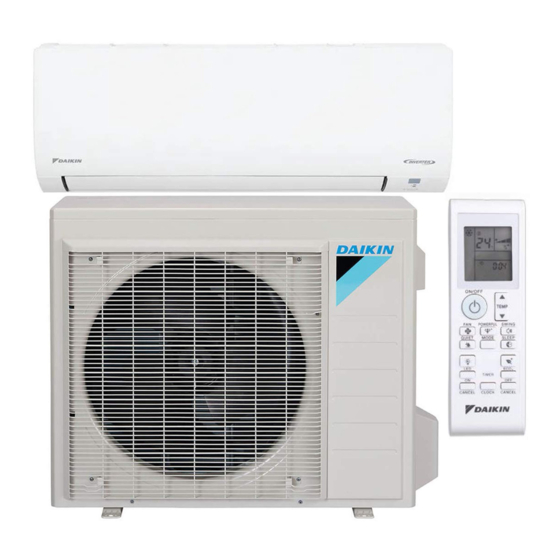
Daikin FTX09NMVJU Installation Manual
Hide thumbs
Also See for FTX09NMVJU:
- Service manual (145 pages) ,
- Operation manual (92 pages) ,
- Installation manual (39 pages)
Table of Contents
Advertisement
MODELS
FTX09NMVJU
FTK09NMVJU
FTX12NMVJU
FTK12NMVJU
FTX15NMVJU
FTK18NMVJU
FTX18NMVJU
FTK24NMVJU
FTX24NMVJU
FTKN09NMVJU
FTXN09NMVJU
FTKN12NMVJU
FTXN12NMVJU
FTKN18NMVJU
FTXN18NMVJU
FTKN24NMVJU
FTXN24NMVJU
DAIKIN ROOM AIR CONDITIONER
INSTALLATION MANUAL
R410A Split Series
Installation manual
Manuel dinstallation
Manuel dinstallation
Manual de instalación
Advertisement
Table of Contents

Summary of Contents for Daikin FTX09NMVJU
-
Page 1: Installation Manual
DAIKIN ROOM AIR CONDITIONER INSTALLATION MANUAL R410A Split Series Installation manual Manuel dinstallation Manuel dinstallation Manual de instalación MODELS FTX09NMVJU FTK09NMVJU FTX12NMVJU FTK12NMVJU FTX15NMVJU FTK18NMVJU FTX18NMVJU FTK24NMVJU FTX24NMVJU FTKN09NMVJU FTXN09NMVJU FTKN12NMVJU FTXN12NMVJU FTKN18NMVJU FTXN18NMVJU FTKN24NMVJU FTXN24NMVJU... -
Page 2: Table Of Contents
Contents Safety Considerations ������������������������������������ 1 Refrigerant Piping Work ��������������������������������� 9 1. Flaring the pipe end ............. 9 Accessories ����������������������������������������������������� 3 2. Refrigerant piping ............9 Choosing an Installation Site ������������������������ 3 Installation Tips ����������������������������������������������� 10 1. Indoor unit ..............3 1. - Page 3 Corroding copper pipes or soldered parts may result in is shorted and operated forcibly, or parts other than those refrigerant leakage. specified by Daikin are used, fire or explosion may occur. (c) Near machinery emitting electromagnetic waves. Electromagnetic waves may disturb the operation of the control system and cause the unit to malfunction.
-
Page 4: Accessories
Accessories Mounting plate fixing screw Titanium apatite photocatalytic Mounting plate 3/16” × 1” (M4 × 25mm) air-purifying filter * Fixing screw for remote controller Wireless remote controller Remote controller holder holder 1/8” × 13/16” (M3 × 20mm) Indoor unit fixing screw G Dry battery AAA. -
Page 5: Indoor Unit Installation Diagram
Indoor Unit Installation Diagram How to attach the indoor unit Mounting Hook the hooks of the bottom frame plate to the mounting plate. A Mounting plate If the hooks are difficult to hook, remove the front grille. Hook How to remove the indoor unit Push up the marked area (at the lower part of the front grille) to Bottom frame... -
Page 6: Indoor Unit Installation
Indoor Unit Installation 1� Installing the mounting plate • The mounting plate should be installed on a wall which can support the weight of the indoor unit. 1) Temporarily secure the mounting plate to the wall, make sure that the panel is completely level, and mark the drilling points on the wall. -
Page 7: Drilling A Wall Hole And Installing Wall Embedded Pipe
2� Drilling a wall hole and installing wall embedded pipe WARNING For metal frame or metal board walls, be sure to use a wall embedded pipe and wall hole cover in the feed-through hole to prevent possible heat, electric shock, or fi re. •... - Page 8 Indoor Unit Installation 3-2� Left-side, left-back, or left-bottom piping How to replace the drain plug and drain hose • Replacing onto the left side Drain hose attachment position The drain hose is on the back of the unit. 1) Remove the fixing screw of drain hose on the right and remove the drain hose.
-
Page 9: Wiring
4� Wiring 1) As shown in the illustration, insert the wires including the ground wire into the conduit and secure them with lock nut onto the conduit mounting plate. 2) Strip wire ends (3/4 inch (20mm)). 3) Match wire colours with terminal numbers on the terminal block of indoor and outdoor unit and fi rmly secure the wires in the corresponding terminals with screws. -
Page 10: Refrigerant Piping Work
Refrigerant Piping Work 1� Flaring the pipe end 1) Cut the pipe end with a pipe cutter. 2) Remove burrs with the cut surface facing downward, Cut exactly at right angles. Remove burrs. so that the filings do not enter the pipe. Flaring 3) Put the flare nut on the pipe. -
Page 11: Installation Tips
2-2� Selection of copper and heat insulation materials When using commercial copper pipes and fi ttings, observe the following: Inter-unit wire Gas pipe • Insulation material: Polyethylene foam Liquid pipe Heat transfer rate: 0.041 to 0.052W/mK (0.024 to 0.030Btu/fth°F (0.035 to 0.045kcal/mh°C)) Be sure to use insulation that is designed for use with HVAC Systems. -
Page 12: Removing And Installing The Front Grille
2� Removing and installing the front grille • Removal method mark area 1) Remove the front panel to remove the air fi lter. Upper hook (3 locations) Push Upper hook down. 2) Remove the 2 screws from the front grille. (The 15, 18 and 24-class models have 3 screws.) 3) In front of the mark on the front grille, there are 3 upper hooks. -
Page 13: Trial Operation And Testing
Trial Operation and Testing 1� Trial operation and testing • Trial operation should be carried out in either COOL or HEAT operation. 1-1� Measure the supply voltage and make sure that it is within the specifi ed range. 1-2� In COOL operation, select the lowest programmable temperature; in HEAT operation, select the highest programmable temperature�... - Page 14 Two-dimensional bar code is a manufacturing code. 3P379970-5B M15B134 (1510) HT...


