GE DCVH480EK Technical Service Manual
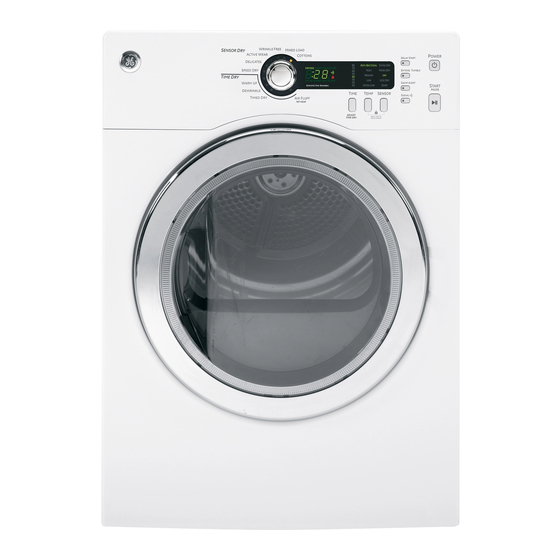
24-in. electric dryer
Hide thumbs
Also See for DCVH480EK:
- Owner's manual (37 pages) ,
- Dimensions and installation information (4 pages) ,
- Owner's manual & installation instructions (108 pages)

Related Manuals for GE DCVH480EK


Summary of Contents for GE DCVH480EK
- Page 1 GE Consumer & Industrial Technical Service Guide November 2009 24-in. Electric Dryer DCVH480EK DCVH485EK 31-9194 GE Appliances General Electric Company Louisville, Kentucky 40225...
- Page 2 If grounding wires, screws, straps, clips, nuts, or washers used to complete a path to ground are removed for service, they must be returned to their original position and properly fastened. GE Consumer & Industrial Technical Service Guide Copyright © 2009 All rights reserved.
-
Page 3: Table Of Contents
Table of Contents Airfl ow ....................................17 Back Cover ...................................29 Belt Switch....................................32 Blower Wheel ..................................34 Component Locator Views ............................18 Control Board ..................................23 Control Board Connections ............................21 Control Features ................................5 Control Panel ..................................22 Cycle Options ..................................8 Door Switch ..................................24 Drive Belt ....................................29 Drum and Bearing ................................30 Drum Lamp Assembly ..............................25 Drum Rollers ..................................28... -
Page 4: Introduction
UV Stabilizers - The control panel has UV stabilizers to prevent yellowing when exposed to sunlight. • The GE 24-in. electric dryer, models DCVH480EK and DCVH485EK, can be installed on top of GE 24-in. HA washers, models WCVH4800K and WCVH4815K. Use stacking kit GE24STACK. -
Page 5: Control Features
Control Features WARNING! To reduce the risk of fire, electric shock, or injury to persons, read the IMPORTANT SAFETY INSTRUCTIONS before operating this appliance. Throughout this manual, features and appearance may vary from your model. Quick Start If the screen is dark, press the POWER button to “wake up” If you selected a TIME DRY the display. -
Page 6: Dry Cycles
Dry Cycles The dry cycle controls the cycle time for the drying process. The chart below will help you match the dry setting with the loads. Sensor Cycles COTTONS For cottons and most linens. MIXED LOAD For loads consisting of cottons and poly blends. WRINKLE FREE For wrinkle-free/easy care and permanent press items. - Page 7 Dry Temp You can change the temperature of your dry cycle. ANTI-BACTERIAL This option may only be used with COTTONS or MIXED LOAD cycles. This option reduces certain types of bacteria. The anti-bacterial process occurs when high heat is used during a portion of this drying cycle.
-
Page 8: Cycle Options
Cycle Options NOTE: Not all features are available on all dryer models. Extend Tumble Minimizes wrinkles by adding The light in the button will light up when approximately 20 minutes of constant EXTEND TUMBLE is on. no-heat tumbling followed by 70 minutes NOTE: It is normal for the drum to pause of intermittent no-heat tumbling after for short periods of time during EXTEND... - Page 9 Lock To lock the dryer, press and hold You can lock the controls to prevent any selections from being made. Or you can the TEMP and SENSOR buttons together for 3 seconds. lock or unlock the controls after you have started a cycle.
-
Page 10: Reversing The Door Swing
Reversing the Door Swing Important Notes: Tools Needed • Read the instructions all the way through before Phillips-head Screwdriver starting. • Handle parts carefully to avoid scratching paint. • Provide a non-scratching work surface for the Hardware Used doors. Mounting Screw •... - Page 11 To reverse the door swing: 5. Remove the inner face. Unplug the dryer from its electrical outlet. 6. Lift and rotate the window assembly 180° and replace. Also rotate the inner face 180° and replace. 2. Remove the hinge bracket anchoring screws. 7.
- Page 12 8. Replace all door screws that were removed. 11. Fasten the hinge back on at the top and bottom with the hinge mounting screws. 9. Remove the female end of the latch from the front panel of the dryer, rotate 180°, and replace on the opposite side.
-
Page 13: Stacking Instructions
Stacking Instructions WARNING! The GE dryer is designed to allow placement (stacking) on top of certain GE front load washers. • Make sure the dryer is unplugged. Washer models that currently qualify are: • More than 2 people are recommended to safely •... - Page 14 Kit Contents (GE Kit #GE24STACK) Installing the Stack Bracket Kit Carefully lay the dryer on its side. Use the Screws (4) packing material so you don’t scratch the fi nish on the dryer. Rubber pads (4) Bracket- stack (R) Bracket- stack (L) 2.
- Page 15 5. Remove washer top cap screw from the rear 11. Refer to the washer Installation Instructions to left. Align left bracket holes with top cap complete the washer installation. screw hole on rear left of the unit and replace 12. Refer to the dryer Installation Instructions to screw.
-
Page 16: Operation Overview
Operation Overview Air enters the dryer cabinet, passing through the heating elements and into the drum. The hot air heats the wet clothes, gradually removing their moisture in the form of water vapor. The moist air is vented through the dryer exhaust. Overall heater temperature is regulated by means of an inlet temperature thermostat, located on top of the heater assembly, and an outlet thermistor, located at the blower. -
Page 17: Airfl Ow
Airfl ow AIR FLOW AND SEALS Proper air fl ow through the dryer is essential for normal operation of the temperature control and safety systems. The back cover must be in place for proper airfl ow. Air is pulled into vents in the rear of the cabinet. The temperature of the air rises by passing thru the electric heaters. -
Page 18: Component Locator Views
Component Locator Views Front view Control Panel Door Switch Drum Lamp Location Reversible Door (Continued Next Page) – 18 –... - Page 19 Front view - cabinet interior Rear Drum Seal Bearing Assembly Idler Bracket Assembly Motor Inlet High Limit Thermostat (Behind Blower Cover) Thermistor (Behind Blower Cover) Blower Wheel – 19 –...
- Page 20 Rear view Terminal Cover Heater Assembly Drum Belt Belt Switch Exhaust Duct – 20 –...
-
Page 21: Control Board Connections
Control Board Connections CN1 - Inlet High Limit, Heater CN2 - Neutral CN4 - DC output to Thermistor, Touch Sensor, Lamp RY1- Motor Relay RY6 - Heater Relay – 21 –... -
Page 22: Control Panel
Dryer Components WARNING: Sharp edges may be exposed when 3. Pull the top of the panel up and out from the top brace, then lift the panel off of the cabinet front. servicing the dryer. Use caution to avoid injury. Wear Kevlar gloves or equivalent protection. -
Page 23: Control Board
Note: In the next step, the button overlay is inserted Control Board into the rear of the buttons on the control panel. The control board is mounted in a housing that is attached to the inside of the control panel. The control board and housing are replaced as an Button Overlay assembly. -
Page 24: Door Switch
5. Pull the top of the front panel away from the Front Panel cabinet, then disconnect the door switch wire harness. Removal of the front panel provides access to the drum support and blower wheel. The front panel is inserted into 3 hooks attached to the bottom of the cabinet and held in place with 6 Phillips-head screws. -
Page 25: Drum Lamp Assembly
3. Open the door. The lamp assembly is secured in place by a groove in the housing and locked in place with 4. Press the locking tab in and pull the switch out an elongated ridge that engages a notch in the from the front of the panel. -
Page 26: Touch Sensors
To remove the touch sensor assembly: Touch Sensors Open the door and remove the lint fi lter. The touch sensor consists of 2 sensors permanently attached to the fi lter inlet. Remove the 2 Phillips-head screws that attach the duct outlet to the drum support. Lower and remove the duct outlet. -
Page 27: Drum Support Assembly
6. Remove the 2 Phillips-head screws that attach Drum Support Assembly the fi lter guide and inlet to the drum support. The drum support assembly houses the lint fi lter assembly, drum lamp, and drum rollers. It is located behind the front panel. The drum support is attached to the cabinet with 4 Phillips-head screws and 4 hooks that engage 4 cutouts in the cabinet. -
Page 28: Drum Rollers
3. Remove the disconnected touch sensor wire Drum Rollers harness from the 2 top front wire retainers. The front of the stainless steel drum rotates on 2 rollers attached to the inside of the drum support. Wire Retainer Wire Retainer 4. -
Page 29: Back Cover
Back Cover Drive Belt It is necessary to remove the back cover to access The drive belt extends from the motor pulley, past the heater assembly, idler bracket, and belt switch. the idler pulley, and around the perimeter of the dryer drum. -
Page 30: Drum And Bearing
To replace the drive belt: Drum and Bearing Lift the front of the drum up, then place the belt The dryer drum is made of 304 stainless steel and in position around the circumference of the has three replaceable drum baffl es attached to the drum. -
Page 31: Rear Drum Seal Assembly
The drum shaft fi ts into the bearing located in the Rear Drum Seal Assembly center back of the cabinet. The rear drum seal assembly consists of a felt seal The bearing is attached to the cabinet with 4 that is permanently attached to a rubber gasket Phillips-head screws and a tab located at the top. -
Page 32: Belt Switch
4. Disconnect the wire harness from the belt Belt Switch switch. The belt switch is housed inside a cover, inserted over a post on the back of the motor baseplate, and attached with a Phillips-head screw. The switch is activated by the movement of the idler bracket assembly. -
Page 33: Idler Bracket Assembly
Idler Bracket Assembly Outlet Thermostat The idler bracket assembly maintains proper tension The outlet thermostat is located on the upper on the drive belt to minimize belt slippage. The idler rear area of the blower housing. It is above the bracket assembly consists of the idler bracket, thermistor. -
Page 34: Blower Wheel
Thermistor Blower Wheel The thermistor is located on the upper rear area The blower wheel is held to the blower motor shaft of the blower housing. It is below the outlet with a 14-mm hex nut. To remove the blower wheel, thermostat. -
Page 35: Motor
Note: In the following step, to prevent the blower Operation of the motor can be checked by using the wheel from turning while removing the center nut, service test mode. (See Service Test Mode apply a 7/8-in. wrench to the nut on the end of the Specifi... -
Page 36: Heater Assembly
5. From the rear of the cabinet, peel back the Heater Assembly wiring grommet from the wiring entry opening. WARNING: Sharp edges may be exposed when servicing the heater. Use caution to avoid injury. Wear Kevlar gloves or equivalent protection. The heater assembly is located on the back of the cabinet. - Page 37 Inlet High Limit Thermostat The inlet high limit thermostat is attached to the top of the heater assembly and located to the right of the inlet thermostat, as viewed from the back of the dryer. Two blue wires are connected to the inlet high limit thermostat.
-
Page 38: Service Test Mode
Troubleshooting Service Test Mode The dryer control has a service test mode that can be utilized by the service technician in order to test critical components and to access error codes. This test mode will help the service technician to quickly identify failed or improperly operating dryer components. - Page 39 The following tables shows the diagnostic tests and the button sequence that is required to perform them. Service Test Mode Sequence Note Displays software version number START/PAUSE Software Version Returns to service mode screen POWER Error Codes START/PAUSE Displays software version number START/PAUSE Clear highlighted error code from machine (During t02 test)
-
Page 40: Error Codes
Error Codes Error Component, Description and Corrective Action Code System, or Test No Error There are no errors to display. Thermistor Short Thermistor voltage is over 4.8 VDC for more than 5 seconds. Check the PCB, wire, and thermistor. Thermistor Open Thermistor voltage is under 0.2 VDC for more than 5 seconds. -
Page 41: Schematics And Wiring Diagrams
Schematics and Wiring Diagrams Electric Model WARNING: Disconnect electrical power before servicing. Caution: Label all wires prior to disconnection. Wiring errors can cause improper and dangerous operation. Verify operation after servicing. – 41 –... -
Page 42: Warranty
This warranty is extended to the original purchaser and any succeeding owner for products purchased for home use within the USA. If the product is located in an area where service by a GE Authorized Servicer is not available, you may be responsible for a trip charge or you may be required to bring the product to an Authorized GE Service location for service.