
Related Manuals for GE DCVH480EK0WW


Summary of Contents for GE DCVH480EK0WW
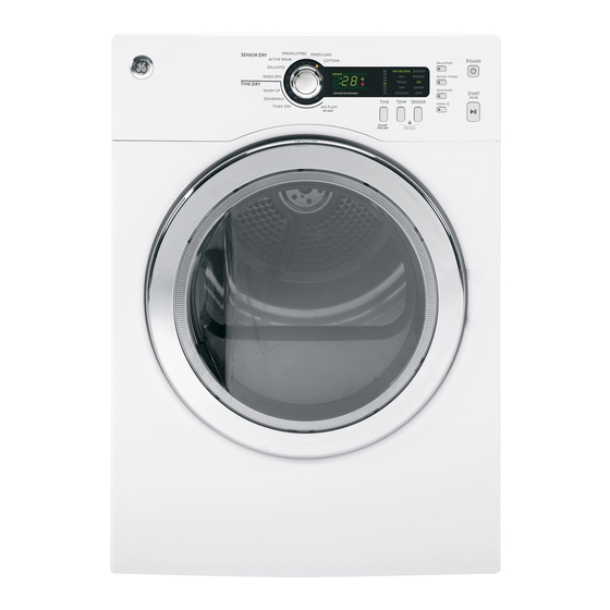
- Page 1 GE 24” DCVH480 Series Dryer DCVH480EK0WW DCVH485EK0MS Service guide 31-9194 MK 11/12/2009...
- Page 2 IMPORTANT SAFETY NOTICE The information in this presentation is intended for use by individuals possessing adequate backgrounds of electrical, electronic, & mechanical experience. Any attempt to repair a major appliance may result in personal injury & property damage. The manufacturer or seller cannot be responsible for the interpretation of this information, nor can it assume any liability in connection with its use.
- Page 3 GE Factory Service Employees are required to use safety glasses with side shields, cut resistant (Dyneema®) gloves & steel toe shoes for all repairs. Plano Safety Glasses Steel Toe Shoes Dyneema® Cut Resistant Glove Prescription Safety Glasses Safety Glasses must be compliant with ANSI Z87.1-2003...
-
Page 4: Warranty
Warranty Copyright 2009... -
Page 5: Nomenclature Location
Nomenclature Location Model and Serial Number Copyright 2009... -
Page 6: Mini Manual Location
Mini Manual Location Mini Manual Mini Manual located behind control panel Copyright 2009... -
Page 7: Control Panel Selections
Control Panel Selections • Time - adjusts the “Time Dry” cycles • Sensor - adjusts dryness level for “Sensor Cycles” • Temp - adjusts the temperature setting for all non delicate heat cycles Copyright 2009... -
Page 8: Control Lockout
Control Lock Out Press “Power Pad” then hold the “TEMP and SENSOR” pads for 3 seconds. The control can be locked out with or without a cycle selected. Note: If the control is locked out and a cycle is running the power pad will still function. -
Page 9: Damp Alert
Damp Alert • This option causes the dryer to beep when clothes have dried to a damp level. • The dry cycle will continue running • Damp Alert can only be selected for “dry, more dry and extra dry” sensor dry selections Copyright 2009... -
Page 10: Stacked Installation
STACKED INSTALLATION • Dryer can be stacked on washer as an installation option • Optional stacking kit required (GE kit # GE24STACK) • Shipping weight of dryer is 100lbs Tools Required: Phillips screwdriver Open end or adjustable wrench Pliers Level... - Page 11 Stacked Installation Copyright 2009...
- Page 12 Stacked Installation Copyright 2009...
- Page 13 Stacked Installation Copyright 2009...
- Page 14 Stacked Installation Complete Copyright 2009...
-
Page 15: Electrical Connection
Electrical Connection Copyright 2009... - Page 16 REVERSEABLE DOOR SWING • Read the directions all the way through before starting • Handle parts carefully to avoid scratching paint • Provide a non-scratching work surface for the doors • Separate screws by their related parts to avoid using them in the wrong places •...
-
Page 17: Reversing The Door Swing
Reversing The Door Swing Copyright 2009... - Page 18 Reversing The Door Swing Copyright 2009...
-
Page 19: Door Removal
Door Removal Remove these two screws to remove the door and hinge assembly Copyright 2009... -
Page 20: Lint Screen
Lint Screen Copyright 2009... - Page 21 Lint Screen The lint screen unfolds for cleaning Copyright 2009...
-
Page 22: Door Switch
Door Switch Door switch can be checked using the service “Test Mode”. Copyright 2009... - Page 23 Door Switch This clip will need to be removed when replacing the door switch. This clip is for factory assembly only and will not need to be reinstalled. Copyright 2009...
-
Page 24: Drum Lamp
Drum Lamp Groove • The drum lamp assembly as seen with front panel removed • The lamp assembly is inserted from inside the drum area • The lamp is secured in place by a groove in the rubber housing Copyright 2009... - Page 25 Drum Lamp • The dryer features LED lighting • 12VDC is supplied to the lamp assembly by the PCB (Lamp out of circuit) • 6.53 VDC with lamp in circuit and operating • Lamp assembly is accessible from the front of the dryer •...
-
Page 26: Control Panel Disassembly
Control Panel Disassembly Top removal • Remove the two rear hex head Phillips screws • Slightly lift rear of top panel and slide towards the rear of dryer Copyright 2009... - Page 27 Control Panel Disassembly • Remove the two screws securing the control panel • Lift up on the control panel and pull forward to disengage the control panel Copyright 2009...
- Page 28 Control Panel Disassembly PCB Assembly Copyright 2009...
- Page 29 Control Panel Disassembly • Remove the control knob by pulling briskly off of the PCB shaft • Note the alignment of the “D” shaft when replacing the knob Copyright 2009...
- Page 30 Control Panel Disassembly PCB Removal Remove the four Phillips screws Copyright 2009...
- Page 31 Control Panel Disassembly Press in on locking tabs to release the PCB Copyright 2009...
- Page 32 Control Panel Disassembly Rubber push buttons are available as a separate part Copyright 2009...
- Page 33 Control Panel Disassembly Plastic push buttons are available as a separate part Copyright 2009...
-
Page 34: Front Panel Removal
Front Panel Removal • Remove the 6 Phillips screws and close the door • Lean the front panel forward and lift off base Copyright 2009... -
Page 35: Front Drum Support Removal
Front Drum Support Removal Lift up to disengage • Remove the four Phillips screws • Disconnect the sensor harness • Disconnect the lamp assembly harness Copyright 2009... - Page 36 Front Drum Support Removal • When unlocking the front drum support make sure after lifting up, slide the bottom out towards the front and drop down to release the upper support tab from the control panel support bracket Copyright 2009...
- Page 37 Front Drum Support Removal The replaceable drum rollers are mounted to the front drum support Remove the triangle retainer clip to remove roller Copyright 2009...
-
Page 38: Filter Inlet Assembly
Filter Inlet Assembly Sensor wiring • Remove the three Phillips screws securing the filter inlet assembly • Disconnect sensor wiring from front side of drum support • Sensor can be tested in service mode Copyright 2009... - Page 39 Filter Inlet Assembly Removal Lift assembly up and out of the drum Remove the two front screws support Copyright 2009...
-
Page 40: Belt Removal
Belt Removal Remove the nine screws and two Belt and Idler access slots securing the rear cover Copyright 2009... - Page 41 Belt Removal • Push the idler to the right to release belt tension • Remove belt from motor pulley Copyright 2009...
-
Page 42: Drum Removal
Drum Removal Slide drum assembly forward and remove from cabinet Copyright 2009... -
Page 43: Rear Drum Bearing Shaft
Rear Drum Bearing Shaft • If rear drum shaft is damaged the drum assembly will need to be replaced • The washer bearing is a replaceable part Copyright 2009... - Page 44 Rear Drum Bearing Components Felt Gasket assembly Rear drum bearing assembly Felt gasket bracket Copyright 2009...
- Page 45 Rear Drum Bearing Components • Remove the three Phillips head screws from the felt gasket bracket • Note the “UP ARROW” to ease in reassembly Copyright 2009...
-
Page 46: Rear Drum Gasket Components
Rear Drum Gasket Components • Note the up arrow when reinstalling the gasket and bracket assembly • The gasket assembly is attached to the gasket bracket with push through dart tabs Copyright 2009... -
Page 47: Belt Switch
Belt Switch The belt switch is secured to the motor bracket with one Phillips head screw Copyright 2009... - Page 48 Belt Switch • The belt switch is a normally closed switch (actuator not engaged) • When a belt breaks it causes the switch to open (actuator engaged) • The idler assembly utilizes the spring tension to engage the switch when the belt is broken Copyright 2009...
-
Page 49: Idler Assembly
Idler Assembly The idler assembly is attached to the motor bracket with a Phillips head shoulder screw and spring Copyright 2009... -
Page 50: Blower Wheel Removal
Blower Wheel Removal Remove the two Phillips screws securing the blower housing cover Copyright 2009... - Page 51 Blower Wheel Removal • Use adjustable wrench on belt • Remove the 14mm nut pulley to hold shaft when removing or • Left hand threads installing blower wheel • Turn clockwise to remove Copyright 2009...
-
Page 52: Outlet Thermostat And Thermistor
Outlet Thermostat and Thermistor Blower Duct • The outlet thermostat and thermistor are located on the inside of the blower housing • Both are removed with a single Phillips head screw Copyright 2009... -
Page 53: Motor Removal
Motor Removal Motor harness connection Belt switch wiring • Disconnect motor harness • Remove front and rear motor clamps • Remove blower wheel Copyright 2009... -
Page 54: Motor Testing
Motor Testing Red # 1 centrifugal switch Yellow # 5 N to door switch Gray # 4 L1 from RY1 through belt switch Blue # 2 centrifugal switch from outlet thermostat Copyright 2009... - Page 55 Heater Airflow Heater Rear cover (Air Duct) Flow T’Stats Rear view w/o heater duct Copyright 2009...
-
Page 56: Heater Location
Heater Location Air Flow Remove rear cover to access the heater assembly Copyright 2009... - Page 57 Air Flow Cool Air Intake Copyright 2009...
-
Page 58: Heater Removal
Heater Removal Remove the two Phillips screws securing the heater Copyright 2009... -
Page 59: Heater Assembly
Heater Assembly • Dual Elements 600W and 1600W • Replaced as a complete assembly Copyright 2009... - Page 60 Heater Removal Remove protective heater wire harness Disconnect heater harnesses located grommet under top panel Copyright 2009...
- Page 61 Heater Assembly Hi-Limit Inlet Thermostat Thermostat Complete Heater Assembly with harness and thermostats Copyright 2009...
- Page 62 Heater Assembly Non- Removable Tabs • Thermostats are not replaceable • Must replace the heater assembly Copyright 2009...
- Page 63 Heater Testing 1600W + 600W heater = 2200W 9.1 Amps Heater 1 Gray to Brown 1600W 35Ω 6.8 Amps Heater 2 Gray to Black 600W 94Ω 2.5Amps Copyright 2009...
-
Page 64: Thermistor Values
Thermistor Values Thermistor Values Copyright 2009... - Page 65 Thermostats Blower Housing Heater Assembly (non replaceable) Copyright 2009...
-
Page 66: Pcb Wiring
PCB Wiring Heater 1 Heater 2 Door Switch Motor Relay Copyright 2009... -
Page 67: Pcb Component Locations
PCB Component Locations CN4 DC Output CN2 Door Check CN1 Heater and High Limit RY1 Motor Relay RY6 Heater Relay Copyright 2009... - Page 68 PCB Component Locations Thermistor = pin 11 , 7 Touch sensor = pin 5, 6 Drum Lamp pin 1, 4 7 6 5 All DC outputs Copyright 2009...
- Page 69 PCB Component Locations To (DC power supply) Door Check • CN2 senses the door switch • Allows the drum lamp to operate when control is on • Turns off the motor when door is opened during a cycle Copyright 2009...
-
Page 70: Pcb Motor Testing
PCB Motor Testing To check the motor: • CN2 pin 1 (gray) to RY1 (blue) = approximately 1.7 ohms (Resistance of start and run windings) • A reading of approximately 3.6 ohms indicates an open winding, stuck open start switch or open wiring •... -
Page 71: Pcb Heater Testing
PCB Heater Testing Heaters 130Ω Hi Limit 0Ω if closed To check the heaters: • Both heaters CN1 pin 1 (Black) to RY6 (Red) =approximately 130Ω • Hi Limit Thermostat RY6 (Black) to CN1 pin 3 (Blue) = 0Ω if closed Copyright 2009... -
Page 72: Service Test Mode
Service Test Mode • Enter Service Mode from An Idle State (Do Not Press The Power Button): • Press Signal then Extended Tumble, Signal then Extended Tumble within 3 seconds Copyright 2009... - Page 73 Service Test Mode • T01 will appear in the display when entered into the service test mode Copyright 2009...
- Page 74 Service Test Mode • The rotary selector knob advances the test selections • To initiate a test sequence press the START/PAUSE button Copyright 2009...
- Page 75 Service Test Mode • To return back to the test selection press the POWER button • Press the POWER button a second time will exit the service mode Copyright 2009...
- Page 76 Service Test Mode Copyright 2009...
- Page 77 Service Test Mode Copyright 2009...
- Page 78 Schematic Copyright 2009...