
Related Manuals for Motorola QIP6200 Series


Summary of Contents for Motorola QIP6200 Series
- Page 1 User Guide QIP6200/QIP64xx Series Set-TopTerminals High-Definition Watch and Record DVR...
- Page 2 Graphical symbols and supplemental warning marking locations on bottom of terminal. WARNING TO REDUCE THE RISK OF FIRE OR ELECTRIC SHOCK HAZARD, DO NOT EXPOSE THIS APPLIANCE TO RAIN OR MOISTURE. CAUTION TO PREVENT ELECTRICAL SHOCK, DO NOT USE THIS (POLARIZED) PLUG WITH AN EXTENSION CORD, RECEPTACLE, OR OTHER OUTLET UNLESS THE BLADES CAN BE FULLY INSERTED TO PREVENT BLADE EXPOSURE.
-
Page 3: Important Safety Instructions
IMPORTANT SAFETY INSTRUCTIONS Read these instructions. Keep these instructions. Heed all warnings. Follow all instructions. Do not use this apparatus near water. Clean only with dry cloth. Do not block any ventilation openings. Install in accordance with the manufacturer’s instructions. Do not install near any heat sources such as radiators, heat registers, stoves, or other apparatus (including amplifiers) that produce heat. -
Page 4: Regulatory Information
According to 47 CFR, Parts 2 and 15 for Class B Personal Computers and Peripherals; and/or CPU Boards and Power Supplies used with Class B Personal Computers, Motorola, Inc., 6450 Sequence Drive, San Diego, CA 92121, 1-800-225-9446, declares under sole responsibility that the product identifies with 47 CFR Part 2 and 15 of the FCC Rules as a Class B digital device. -
Page 5: Software License
TERMINATE AUTOMATICALLY if you fail to comply with the terms of this License. Motorola is not responsible for any third party software that is provided as a bundled application, or otherwise, with the Software or that is downloaded to, or otherwise installed on, the Product. - Page 6 ___________________________________________________________________________________ Copyright © 2005 by Motorola, Inc. All rights reserved. No part of this publication may be reproduced in any form or by any means or used to make any derivative work (such as translation, transformation or adaptation) without written permission from Motorola, Inc.
-
Page 7: Table Of Contents
Turning Power On and Off... 8 Changing Channels ... 8 Adjusting the Volume... 8 Electronic Program Guide ... 8 Digital Video Recorder (DVR) – QIP64xx models only ... 9 What is DVR? ... 9 Record Programming ... 9 Maintain a Personal Program Library ... 9 Control Live TV... - Page 8 IEEE 1394 ... 25 DVI or HDMI ... 26 Connecting Your Set-top to an HDTV – Audio Only ... 27 Connecting HDTV – Audio Only... 28 Connecting Your Set-top to an A/V Receiver – Audio Only... 29 Connecting an A/V Receiver – Audio Only ... 30 Connecting your Set-Top to a Stereo TV...
-
Page 9: Introduction
In addition, the QIP64xx offers full DVR functionality to record and play back the shows you want to watch. With its second tuner, the QIP64xx also allows “watch and record”... -
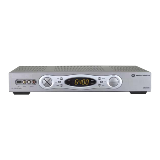
Page 10: Qip6200/64Xx - Front And Back Panels
POWER switch – Turns the QIP6xxx on or off MSGS. indicator – Is lit when a message is waiting RECORD indicator – Is lit when the DVR is recording (QIP64xx models only) SELECT switch – Used for selecting menu options GUIDE switch –... - Page 11 Item Description DISPLAY – Displays channel number and time of day REMOTE indicator – Is lit when remote control is in use CHANNEL – Scrolls up or down through the channels * Feature is enabled by your service provider with associated EPG software.
-
Page 12: Back Panel Description
Back Panel Back Panel Description Item Description RF IN – Connects to digital TV input from your service provider RF OUT – Connects to TV or VCR (optional interface) IR – Enables QIP6xxx to control a VCR while recording a selected program (not supported by all program guides) SPDIF (coaxial) –... - Page 13 Item Description AUDIO IN (Left and Right aligned vertically) – Connects to a baseband audio output from a VCR, camcorder, or other audio device (requires EPG support) AUDIO OUT (Left and Right aligned vertically) Connect to baseband audio input of a stereo receiver TVPC –...
-
Page 14: Operation
OPERATION Turning Power On and Off Press on the front panel to turn the set-top on or off. When using POWER the remote control, be sure you press Changing Channels You can change channels in two ways: • Press CHANNEL press + or - on the remote control to step through the CHANNEL... -
Page 15: Digital Video Recorder (Dvr) - Qip64Xx Models Only
QIP64xx's hard drive allows recording and playback to occur simultaneously. A DVR offers the ability to control your viewing experience by pausing (time shifting) live TV and providing trick playback modes (pause, fast forward, slow forward, fast rewind, slow rewind). You may experience a slight delay between time-shifted and live TV. -
Page 16: Simultaneously Record Two Shows
Simultaneously Record Two Shows Record two programs from two different channels at the same time Simultaneously Record Shows and Watch a Recorded Program Watch a program recorded on your QIP64xx while recording up to two other programs at the same time. You can also easily switch between viewing the pre-recorded program and either of the programs that you are recording. -
Page 17: Optimizing Your Set-Top For High-Definition Tv
TV. The Motorola QIP6xxx delivers high-quality video for HDTVs using the YPbPr (component), HDMI, and IEEE 1394 connectors. This section describes how to use the on-screen display to set your QIP6xxx to automatically optimize both standard and HD video based on your HDTV and personal preferences. - Page 18 This screen appears if the HDMI port is active: Note: For HDMI or YPbPr, only PC1 or PC2 can be selected. TV TYPE HDMI/YpbPr OUTPUT 4:3 OVERRIDE CLOSED CAPTION SERVICE SELECTION ANALOG DIGITAL FONT SIZE FONT STYLE FONT COLOR FONT OPACITY FONT EDGE TYPE FONT EDGE COLOR BACKGROUND COLOR...
- Page 19 Use the remote control or the navigate the on-screen display (the HD settings are described in the table on the following pages): • Press the ▲ and ▼ keys to highlight the setting you wish to change. Press the ► key to select an option for that setting. •...
-
Page 20: User Settings
User Settings Setting Description Sets the aspect ratio. The front panel display indicates the TV TYPE type you select. The default is 16:9. Options are 16:9 for wide screen TVs, or 4:3 LETTERBOX or 4:3 PAN/SCAN for standard TVs: • •... - Page 21 Setting Description Sets the display format for 4:3 standard-definition 4:3 OVERRIDE programming. If the YPrPb OUTPUT is set to 1080i, 720p, or 480p, this setting defaults to 480i. If the YPrPb OUTPUT is set to 480i, this setting defaults to OFF and cannot be changed.
- Page 22 Setting Description FONT OPACITY Sets the opacity for closed captions — AUTO, TRANSPARENT, TRANSLUCENT, SOLID, or FLASHING. The default is AUTO. FONT EDGE Sets the edge appearance for closed captions — AUTO, TYPE NONE, RAISED, DEPRESSED, UNIFORM, LEFT SHADOWED, or RIGHT SHADOWED. The default is AUTO. FONT EDGE Sets the edge color for closed captions —...
-
Page 23: On-Screen Graphics
QIP6200/QIP64xx User Guide ON-SCREEN GRAPHICS The QIP6xxx can generate graphics that overlay the video programming or fill the entire television screen. Common examples include on-screen menus (such as the User Setting menu), closed captions, and electronic program guides. The QIP6xxx overlays these graphics whenever you open a menu, enable closed captions, or scroll through a program grid. -
Page 24: Connecting Your Set-Top
CONNECTING YOUR SET-TOP This section describes how to connect the QIP6xxx set-top to your home entertainment system. Instructions and diagrams are included for the following connections to the QIP6xxx: • High-Definition Television (HDTV) • A/V Receiver – Audio • Stereo TV •... -
Page 25: Important Safety Considerations
Important Safety Considerations Follow these important safety guidelines when positioning and connecting the set-top: • Position the set-top with at least two inches of space above and on all sides. • Do not block the slots and openings on the set-top. •... -
Page 26: Video Connection Options
Video Connection Options The QIP6xxx offers six different video connection options. Component video, HDMI, and IEEE 1394 allow you to view both HD and standard TV programming. Composite video, S-video, and RF coaxial connections allow you to view standard definition TV programming; HDTV programming can also be viewed, but it will be converted to standard format. - Page 27 • RF Output – SDTV If your TV has an RF input only, connect it to the RF output on the set-top. The TV must be tuned to channel 3 or 4. The IEEE 1394 is a video and audio connection, so no audio connections are required if you are using the IEEE 1394 connection and you plan to use your TV’s speakers as the primary audio source.
-
Page 28: Recording Your Connections
RECORDING YOUR CONNECTIONS Use this diagram to record connections between your home entertainment components. You can use this diagram to reconnect your system if you move the equipment or add new equipment. Disconnect the power from the set-top before connecting or changing any connections. - Page 29 QIP6200/QIP64xx User Guide...
-
Page 30: Connecting Your Set-Top To An Hdtv - Video Only
CONNECTING YOUR SET-TOP TO AN HDTV – VIDEO ONLY... -
Page 31: Connecting Hdtv - Video Only
Connecting HDTV – Video Only If you have a TV with a DVI connector, you will need an HDMI adapter cable or an HDMI adapter. If your TV has a DVI port, you can plug a DVI cable directly from the TV to the HDMI adapter on the set-top. Or, you can use an HDMI adapter cable to connect the units port-to-port. -
Page 32: Dvi Or Hdmi
DVI or HDMI If your TV has a DVI or HDMI input, use the set-top’s your video using the appropriate interface cable or adapter. Remember, if your TV has a DVI input, you will need to connect audio as well. Refer to “Connecting Your Set-Top to an HDTV – Audio Only” after you complete the appropriate step below. -
Page 33: Connecting Your Set-Top To An Hdtv - Audio Only
QIP6200/QIP64xx User Guide CONNECTING YOUR SET-TOP TO AN HDTV – AUDIO ONLY... -
Page 34: Connecting Hdtv - Audio Only
Connecting HDTV – Audio Only If your equipment supports it: • OPTICAL SPDIF used in place of the stereo audio outputs ( cases, these outputs offer a higher level of audio quality, including support for Dolby Digital 5:1 surround sound. Otherwise: •... -
Page 35: Connecting Your Set-Top To An A/V Receiver - Audio Only
QIP6200/QIP64xx User Guide CONNECTING YOUR SET-TOP TO AN A/V RECEIVER – AUDIO ONLY... -
Page 36: Connecting An A/V Receiver - Audio Only
Connecting an A/V Receiver – Audio Only There are three options available for audio connections to your A/V receiver: • Optical ( OPTICAL SPDIF • Coaxial ( SPDIF • Stereo audio ( AUDIO R If your equipment supports it, the optical ( coaxial ( connector) audio outputs may be used in place of the SPDIF... -
Page 37: Connecting Your Set-Top To A Stereo Tv
QIP6200/QIP64xx User Guide CONNECTING YOUR SET-TOP TO A STEREO TV... -
Page 38: Connecting A Stereo Tv
Connecting a Stereo TV This video connection method does not support HD video. To connect an HDTV, see “Connecting Your Set-Top to an HDTV – Video Only.” Connect an RF coaxial cable to the service provider’s wall outlet and to the RF IN Connect the stereo audio cable to the the set-top and to the... -
Page 39: Connecting Your Set-Top To A Stereo Tv And Stereo Vcr
CONNECTING YOUR SET-TOP TO A STEREO TV AND STEREO VCR RF (75 ohm) connector connector C A U TI O N R I S K O F E L E C T R I C S H O C K D O N O T O P E N RF OUT RF IN... -
Page 40: Connecting A Stereo Tv And Stereo Vcr
Connecting a Stereo TV and Stereo VCR This video connection method does not support HD video. For connecting an HDTV, see “Connecting Your Set-Top to an HDTV – Video Only.” Connect an RF coaxial cable to the service provider’s wall outlet and to the CABLE IN Connect a stereo audio cable to the... -
Page 41: Connecting Your Set-Top To An A/V Receiver, Tv, And Vcr
QIP6200/QIP64xx User Guide CONNECTING YOUR SET-TOP TO AN A/V RECEIVER, TV, AND VCR... -
Page 42: Connecting An A/V Receiver, Tv, And Vcr
Connecting an A/V Receiver, TV, and VCR If your equipment supports it: • The optical (square connector) audio outputs may be used in place of the stereo audio outputs ( AUDIO R level of audio quality, including support for Dolby Digital 5:1 surround sound. -
Page 43: Data Devices
QIP6200/QIP64xx User Guide DATA DEVICES Do not attempt to connect data devices without contacting your service provider. Advanced data features require the proper application and network infrastructure to operate. Data Features In addition to high quality audio and video, the set-top has the capability to support the following data interfaces: USB 2.0, Ethernet, SATA, and IEEE 1394. -
Page 44: Troubleshooting
TROUBLESHOOTING Before calling your service provider, review this troubleshooting guide. This information is to help you quickly solve a problem. If your problem persists, contact your service provider. Problem Possible Solution The set-top may have received a software update and The set-top will not may not power on while the new software is being power on... - Page 45 Problem Possible Solution Verify that the There is no audio control has not been pressed. Press when viewing control to restore sound. channels If the set-top audio output is connected to the TV, verify that the If the set-top audio output is connected to a digital/home theater receiver, verify that the receiver is set to the appropriate input source and the receiver has not been pressed.
- Page 46 Problem Possible Solution Verify that the TV is powered on and set to the There is no video appropriate input source for the set-top. on the TV screen Verify that the set-top is powered on and tuned to an authorized digital TV channel. Verify that all video cables between the set-top and the TV are firmly connected.
- Page 47 Problem Possible Solution The set-top cannot generate graphics on all video There are no outputs at all times. If the set-top is set to 1080i, 720p, or graphics, closed 480p output format, graphics are only available on the captions, or HD video outputs (HDMI and component video).
- Page 48 Problem Possible Solution All 4:3 HDTVs display HD programs in letterbox format There are black (black bars above and below the picture) because of the bars above and shape of the display screen. below the picture Turn on the 4:3 OVERRIDE feature in the User Settings menu.
- Page 49 Problem Possible Solution A standard definition program is being stretched to fit the The video is HDTV screen: horizontally distorted on the • HDTV screen • The set-top includes an integrated hard drive and a fan The set-top is for cooling. During normal operation, the set-top emits a making a humming low humming noise, similar to a personal computer.
- Page 50 Visit our website at: www.motorola.com 521696-001 rev B 7/05 MGBI...