Table of Contents
Advertisement
Advertisement
Table of Contents

Related Manuals for Motorola DCH3416


Summary of Contents for Motorola DCH3416
- Page 1 IN STALLAT ION MANUA L DCH3416 Installation Manual...
- Page 3 IMPORTANT SAFETY CONSIDERATIONS The DCH3416 requires careful handling to avoid potential damage to its internal hard disk drive or the loss of recorded data. Be sure to follow these requirements during transportation and installation. The plug is the mains disconnect device. It shall remain readily accessible and operable.
- Page 4 • Consult the dealer or an experienced radio/TV technician for help. Caution: Changes or modifications not expressly approved by Motorola for compliance could void the user’s authority to operate the equipment. This device complies with part 15 of the FCC Rules. Operation is subject to the following two conditions: (1) This device may not cause harmful interference, and (2) this device must accept any interference received, including interference that may cause undesired operation.
- Page 5 FCC DECLARATION OF CONFORMITY Motorola Inc., Connected Home Solutions, 101 Tournament Drive, Horsham, PA 19044, 1-215-323-1000, declares that the DCH3416 receiver complies with 47 CFR Parts 2 and 15 of the FCC rules as a Class B digital device. CANADA INDUSTRY CANADA (IC) This Class B digital device complies with Canadian ICES-003.
-
Page 7: Table Of Contents
CONTENTS 1 Introduction ..............................1 Features ............................... 1 Tuners..............................1 Standard Audio/Video Features......................2 Standard DVR Functionality....................... 2 Standard Data Features ........................3 Standard Miscellaneous Features ....................3 If You Need Help ............................4 Calling for Repairs ............................4 2 Overview ................................5 Front Panel.............................. - Page 8 Figure 3-3 Cabling to a Standard-Definition stereo TV ................14 Figure 3-4 Cabling an audio receiver......................15 Figure 3-5 Sample data devices you can connect to the DCH3416............16 Figure 4-1 Example of the front panel display for the diagnostic main menu .......... 21 Figure 4-2 Example General Status display (no error) .................
- Page 9 CONTENTS Tables Table 1-1 DVR Recording Time Guidelines......................3 Table 2-1 Front panel ...............................5 Table 2-2 Rear panel connections.........................7 Table 3-1 Operational check procedures......................17...
-
Page 11: Introduction
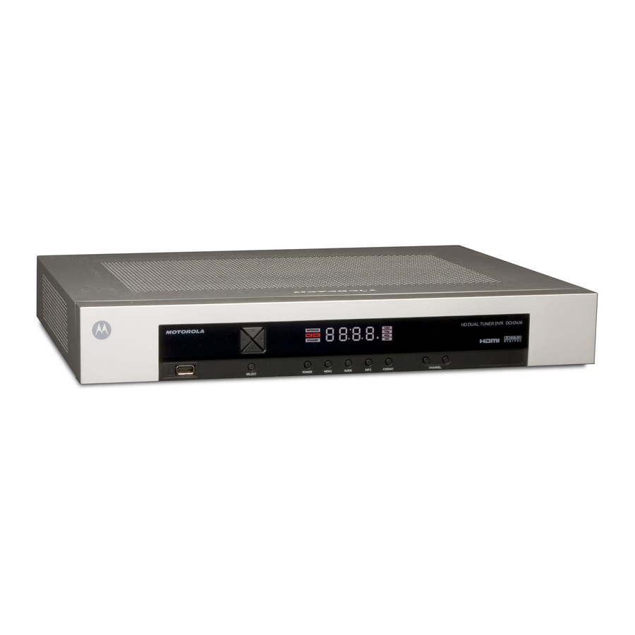
Ethernet and Universal Serial Bus (USB) 2.0 ports for future home networking applications • Adaptability to various software platforms As with all Motorola digital cable receivers, the hardware features are enabled by core operating and third party application software. Figure 1-1 Front and rear views Features Tuners •... -
Page 12: Standard Audio/Video Features
1 INTRODUCTION • One dedicated tuner for the DOCSIS high-speed data/voice services channel, up to 860 MHz • One dedicated tuner for the out-of-band (OOB) control channel Standard Audio/Video Features • ITU standard 64/256 QAM/FEC/enhanced adaptive equalizer • DES based encryption/DCII (via inserted CableCARD™) access control •... -
Page 13: Standard Data Features
1 INTRODUCTION Motorola cannot guarantee the exact amount of programming that each subscriber will be able to record. The approximate time depends on the programming type and the drive size: Table 1-1 DVR Recording Time Guidelines Estimated Recording Hours For:... -
Page 14: If You Need Help
Motorola Online: http://businessonline.motorola.com/ The TRC is on call 24 hours a day, 7 days a week. In addition, Motorola Online offers a searchable solutions database, technical documentation, and low-priority issue creation and tracking. For specific toll-free numbers when calling from outside the United States, please refer to your product manual or our Web page. -
Page 15: Overview
*The availability of certain features is dependent upon application support. Front Panel Format Button The Format button* located on the front panel of the DCH3416 allows you to quickly change the video output format on the Component Video (YPbPr) and HDMI outputs of the product. - Page 16 DCH3416 to operate with your specific television. If you cannot get a video display when the DCH3416 is connected to your television via Component Video or HDMI cables, use the Format button to select a video output format that results in a viewable picture on the display screen.
-
Page 17: Rear Panel
2 OVERVIEW Rear Panel The rear panel contains an unswitched power outlet; connectors for video, audio, and RF cabling; data output; and modem and data interface connectors. Some connectors are not enabled and require the support of application software. Figure 2-2 Rear panel Table 2-2 Rear panel connections Cable In —... -
Page 19: Installation
3 INSTALLATION Before You Begin Before you move or change components on the subscriber’s entertainment system: • Review the installation instructions. • Determine if you are connecting to a standard analog NTSC TV (supporting an RF input), a composite (baseband) video input, or an S-Video input) or a High-Definition TV (supporting component video input, HDMI input, or an IEEE-1394 input). -
Page 20: Video Connection Options
If your TV does not have an S-Video input, use the composite video (video) (composite) output. SDTV only If your TV only has a coaxial RF input, connect it to the DCH3416 RF out connector. Audio Connection Options When connecting to a home theater receiver, depending on its inputs, you can use the... -
Page 21: Installation Overview
(RCA phono) cable. If the TV only has a coaxial RF input, connect it to the DCH3416 RF OUT connector. 2. Determine if you are connecting the audio to a home theater receiver or directly to the TV: •... -
Page 22: Cabling To An Hdtv For Video
For the best possible HDTV video quality: • If the TV has an HDMI input, connect it to the DCH3416 HDMI output. If the TV has a DVI input, you can connect it to the DCH3416 HDMI output using and HDMI-to-DVI converter cable or adapter. -
Page 23: Cabling To An Hdtv And An A/V Receiver
The baseband connections are not necessary because the digital audio port provides a single audio interface for digital channels. Note: If the A/V receiver includes HDMI inputs & output(s) then the DCH3416 HDMI output can be directly connected to the A/V receiver. -
Page 24: Cabling To A Standard-Definition Tv And An A/V Receiver
3 INSTALLATION Cabling to a Standard-Definition TV and an A/V Receiver Figure 3-3 Cabling to a Standard-Definition stereo TV Because some entertainment equipment cannot simultaneously support baseband composite video and S-Video, never simultaneously connect both video inputs. This connection method does not support HDTV. For information, see Cabling to an HDTV for Video in this section. -
Page 25: Cabling To A Standard-Definition Tv And Audio Receiver
3 INSTALLATION Cabling to a Standard-Definition TV and Audio Receiver To connect to an audio receiver, such as a home mini system, use a daisy-chain cabling connection. The A/V configuration illustrated below enables digital stereo recording, including Dolby Digital Surround sound. Use only one set of composite input connectors on the audio receiver: Figure 3-4 Cabling an audio receiver The video connections shown in this illustration do not support HDTV. -
Page 26: Data Device Connections
3 INSTALLATION Data Device Connections The DCH3416 provides optional high-speed data services such as Internet access, USB, Ethernet, and more. The functionality of each data device port requires, and depends on, installed application software. The DCH3416 rear panel provides the following data ports: USB 2.0... -
Page 27: Operational Check For The Remote Control
Feature Testing Procedure Power on Press POWER on the remote control to turn on the DCH3416. Tune to the output channel (3 or 4) if using the RF output. Channel selection Scan through the channels using the CHANNEL + or - keys. - Page 28 3 INSTALLATION 2. Use the remote control or the cursor keys on the front panel to navigate the on- screen menus: • Press the ▲ and ▼ keys to highlight the setting you wish to change. • Press the ► key to select an option. •...
- Page 29 3 INSTALLATION Setting Description HDMI/YPbPr Allows you to specify the video output format of the DCH receiver for all content Output (when the 4:3 override setting is Off) or for all 480p, 720p, and 1080i content (when the 4:3 override is used). Options include 1080i, 720p, 480p, and 480i. By default, the 1080i option is selected.
-
Page 30: Graphics Overlaying The Video
3. To exit the menu and save your settings, press the power or menu key. Graphics Overlaying the Video The DCH3416 can generate graphics that overlay the video programming or fill the entire television screen. Common examples include on-screen menus (such as the User Setting menu), closed captions, and IPG. -
Page 31: Diagnostics
All sample displays are illustrative; actual data may differ from the examples. Using the Diagnostics To use the diagnostics: 1. Ensure that the DCH3416 is installed with the Thin Client software and that it is connected to an AC outlet. 2. Press and immediately press to enable diagnostic mode. -
Page 32: General Status
4 DIAGNOSTICS General Status This diagnostic displays system status information on the OSD and front panel. The information is updated each time the diagnostic is displayed. Figure 4-2 Example General Status display (no error) Environment code Error code... - Page 33 EP15 TSI structure corrupt EP18 Driver initialization failure Connected A DCH-operations connect or disconnect message determines whether the DCH3416 State is CONNECTED or DISCONNECTED. Platform ID A unique 16-bit hexadecimal number that identifies the platform image (also called the ROM ID).
-
Page 34: Purchase Status
The last acknowledged sequence number of a purchase sent by the controller. It is a 16-bit, unsigned hexadecimal number. Last RB Time The last time the DCH3416 attempted to report back purchases to the controller, in GPS seconds. IPPV Status If IPPV is enabled, the IPPV status indicator is on. -
Page 35: Out-Of-Band (Oob) Status
4 DIAGNOSTICS Field Description Prep ACK “Last Prepare for Poll Acknowledge” sequence number and time of the last Report Purchase request sent by the controller. Poll Request Sequence number and time of the last send poll buffer command that was sent by the controller. -
Page 36: Figure 4-4 Front Panel Display For The Oob Diagnostic
When carrier lock has been established, displays an estimate of the AGC as a percentage, with an explanation: GOOD — Good value FAIR — Marginal signal level, check the signal POOR — Unusable signal INVALID — Invalid AGC value Displays the conditional access stream for the DCH3416, in hexadecimal Provider ID... -
Page 37: Agile Oob Tuner Hunting
4 DIAGNOSTICS Field Description EMM PID Displays the packet identifier (PID) stream the DCH3416 tunes to for EMM data, in hexadecimal Network Displays the network PID to which the DCH3416 is tuned to receive network messages, in hexadecimal Hunt Mode The hunt mode includes Hunted, None, Round Robin (RR), Search (SRCH), Fixed Frequency (FIX), or EMM Provider ID (EMM). -
Page 38: In-Band Status
4 DIAGNOSTICS 4. If the frequency is found with the proper EMM Provider ID, then the Front Panel will display the normal OOB receiver status. The OSD “LKC” field will change to display the new frequency. 5. If after 40 seconds the frequency search is not successful, the product will perform a warm reset. -
Page 39: Figure 4-5 Front Panel Display For In-Band Diagnostic
5 Second Error Counts Indicates the number of correctable and uncorrectable digital multiplex errors, up to 9999. It is updated every 5 seconds and reset each time the DCH3416 is power cycled or another digital multiplex is tuned. The maximum value displayed... -
Page 40: Unit Address
4 DIAGNOSTICS Unit Address This diagnostic displays the unit address of the CableCARD if inserted: Figure 4-6 Front panel display of a unit address... - Page 41 Description TvPC Indicates whether the TvPC renewable security system is installed: Installed NO — TvPC is not installed (Note: the DCH3416 does not include a TvPC slot) CableCARD YES — CableCARD is inserted Inserted NO — CableCARD is not inserted Unit A unique decimal number that indicates the unit address or physical address.
-
Page 42: Separable Security
4 DIAGNOSTICS Separable Security This diagnostic displays information on the inserted M-CARD and CableCARD Interface with the DCH. Field Description CARD Interface CableCARD Interface is a status indication of the interface between the Host and CableCARD. It will indicate “Good” if no errors are detected, “Error” if there is an error establishing the CableCARD interface, or “Unsupported CARD”... -
Page 43: Current Channel Status
4 DIAGNOSTICS Field Description CableCARD Object Name Code object name executing on the CableCARD. Object Ver. Code object version executing on the CableCARD. Manufacturer CableCARD manufacturer. HW Version Version number provided by the CableCARD. Current Channel Status This diagnostic displays a status of the last attempted channel you attempted to tune on the in-band stream. -
Page 44: Figure 4-7 Current Channel Status Front Panel Displays
(Digital channels only) The center RF carrier frequency for the digital service. It can be Frequency from 54 to 860 MHz. Authorized Indicates whether the DCH3416 is authorized for the currently tuned service: YES — authorized NO — not authorized Purchasable... - Page 45 4 DIAGNOSTICS Field Description PCR Lock Indicates whether the in-band receiver is locked to the program clock reference (PCR): YES — locked NO — not locked The copy control information: 00 — copy free 01 — no more copies 10 — copy once 11 —...
-
Page 46: Rf Modem (Upstream)
4 DIAGNOSTICS RF Modem (Upstream) This diagnostic displays the RF modem status, if an RF modem is installed in the DCH3416. The information is updated each time this diagnostic is displayed. -
Page 47: Figure 4-8 Rf Upstream Modem Front Panel Display
Center The RF modem center frequency is displayed on the OSD and front panel in MHz. Frequency Requested The value in dB assigned to the DCH3416 during RF leveling (blank if it is not Power Level configured). Actual Power The power level is displayed in dB on the OSD and front panel or is blank if the Level power level has not been set. -
Page 48: Code Modules
Code Modules This diagnostic includes information about the firmware loaded in flash memory and all non-volatile code versions are installed on the DCH3416. When the native suite is running, the diagnostics of the application operating system and all associated objects... -
Page 49: Figure 4-9 Front Panel Display For Code Modules
4 DIAGNOSTICS Figure 4-9 Front panel display for code modules Download data received indicator Download status Number of segments remaining for download to complete. (Figure reflects 17012 segments remaining.) Code module identifier (bPC for the base platform; CODE or SYS for the system object) Alternating with Indicator separating major and... - Page 50 The analog secure processor version in ASCII format Secure Processor Downloadable Lists all objects loaded, or being loaded, onto the DCH3416 in ASCII format. The Object information displayed for each object depends on the running environment. If a Information download is not in progress, the front panel displays the currently running environment Table and version number, as shown in Figure 4-9.
-
Page 51: Memory Configuration
4 DIAGNOSTICS Memory Configuration This diagnostic displays the DCH3416 memory configuration. The information is updated when you display the diagnostic. There is no front panel display for this diagnostic. The Memory Configuration fields are: Field Description System RAM The allocated system RAM in MB. -
Page 52: Audio/Video Status
4 DIAGNOSTICS Audio/Video Status Audio/Video Status diagnostics display information regarding audio and video content and settings configured for the set-top. AUDIO SPDIF Indicates SPDIF Mode as set by application software. OSD Display Description Audio SPDIF mode is not applicable IEC958PCM PCM audio selected Dolby Digital For Dolby Digital selection, the following speaker selection is set:... - Page 53 4 DIAGNOSTICS OSD Display Description UNMUTED Displayed if mute method is not selected MUTE to STILL Displayed if the mute method includes stopping video and presenting a still frame, similar to a pause function MUTE to BLACK Displayed if mute method presents a black screen. Captions The captions mode displays captions present on the service.
- Page 54 4 DIAGNOSTICS Closed Caption service T 1 Closed Caption service T 2 Closed Caption service T 3 Closed Caption service T 4 Primary Lang Primary language established by the provider (default, Service 1) Second Lang Secondary language established by the provider (Service 2) Service 3 Set by the provider Service 3.
-
Page 55: Interface Status
4 DIAGNOSTICS Interface Status The Interface Status diagnostic displays when running in Thin Client. There is no LED display. The information on the OSD is updated when you display the diagnostic. - Page 56 4 DIAGNOSTICS...
- Page 57 Display Identification Data (EDID) register for the connected device, in particular the detailed timing description blocks. The list displays all of the formats that the DCH3416 could read, up to a maximum of 12 formats. If the DCH3416 cannot read any formats, EDID Data is blank. An asterisk (*) after the aspect ratio means the DCH3416 supports the format.
-
Page 58: User Setting Status
4 DIAGNOSTICS User Setting Status This diagnostic displays the user settings. The format may vary. The information on the OSD and front panel is updated when you display the diagnostic. The User Setting Status fields are: Setting Description TV Type Allows you to specify the style of television connected to the DCH receiver. - Page 59 4 DIAGNOSTICS Setting Description display as YPbPr Output in the User Settings Menu. 4:3 Override The 4:3 Override setting allows you to specify the video output format of the DCH receiver when it is tuned to a Standard-Definition program or playing back a Standard- Definition program from the DVR.
-
Page 60: Dvr/Hard Drive Status
This two-page diagnostic displays the DVR and hard-drive status. The DVR/Hard Drive Status fields are: Field Description Enabled Indicates whether the DVR is enabled, based on the DCH3416 Connected State (CONNECTED or DISCONNECTED) and resource availability (resource authorized; hard disk installed and functional): Front panel Description True... - Page 61 4 DIAGNOSTICS Field Description Content The content record version number, displayed without leading zeros Record Ver. Encoder Information about the analog encoder for the IEEE-1394 output and recording analog programs Number Indicates the encoder number — 1 or 2 Type Indicates the encoder type —...
-
Page 62: Docsis Status
4 DIAGNOSTICS Field Description Max Temp For an internal hard drive only, its maximum temperature in degrees F Over Temp Indicates whether the drive is excessively hot: • Yes — The internal drive temperature exceeds 140º F (60º C). The LED Over-Temp Indicator is on and remains lit until the next over-temp sample is taken (at least once an hour). - Page 63 4 DIAGNOSTICS The fields are: Field Description DOCSIS For a DOCSIS-enabled set-top, YES. Otherwise, NO. Enabled Acquire DS The DOCSIS downstream channel acquisition status: Channel • YES — The downstream channel is acquired • NO — The set-top is acquiring the downstream channel •...
- Page 64 4 DIAGNOSTICS Field Description Network Displays whether the cable modem has been granted access to the DOCSIS network: Access • YES — The cable modem was granted DOCSIS network access • NO — The set-top is obtaining DOCSIS network access •...
-
Page 65: Application Specific Information
DOCSIS is not enabled, 0.000 is displayed. Known MAC Displays up to 32 MAC addresses learned by the DCH3416 cable modem, including the Addresses Set-Top MAC and future MAC addresses assigned by DSG, in hexadecimal format xx:xx:xx:xx:xx:xx on two screens if necessary. -
Page 66: Interactive Status
00000000 is displayed when the UPM is not configured or if it is unknown. Upstream ID A four-digit decimal value from 0000 to 9999 assigned by the DAC 6000 to the DCH3416. 0000 is displayed if the Upstream ID is not configured or if it is unknown. - Page 67 This counter increments every time the MAC layer reaches the cell abort count limit. It is Cntr reset by the successful upstream transmission of a cell: for example, when the DCH3416 receives an ACK. If the counter reaches the MAC abort count limit, the DCH3416 assumes the MAC layer is unavailable due to noise, congestion, or some other problem.
-
Page 68: Keypad - Front Panel Indicators
4 DIAGNOSTICS Keypad — Front Panel Indicators This diagnostic verifies the functionality of the front panel indicators and the front-panel keypad. Each highlighted character corresponds with a front-panel key press. -
Page 69: Troubleshooting
5 TROUBLESHOOTING Troubleshooting guidelines follow. If problems still occur after performing the diagnostics, call the TRC for assistance as described in the Introduction. Problem Possible Solution The DCH receiver will The DCH receiver may have received a software update and may not power on while the not power on new software is being installed. - Page 70 4:3 video). • If the DCH3416 is connected to a widescreen TV, verify that the TV TYPE is set to 16:9 in the User Settings menu. Many HD programs are broadcast in pillar-box format with black bars to the left and right of the picture.
- Page 71 “hybrid” aspect ratio and results in a black border surrounding the video on a 4:3 TV. Because this is part of the broadcast, the DCH3416 cannot correct the video. You may be able to minimize the border using the zoom feature on the TV.
- Page 72 Motorola, Inc. 101 Tournament Drive Horsham, PA 19044 U.S.A. http://www.motorola.com 537535-001-b 12/07...