Canon MultiPASS MP390 Service Manual
Hide thumbs
Also See for MultiPASS MP390:
- User manual (187 pages) ,
- Setup sheet (8 pages) ,
- Brochure & specs (6 pages)

Related Manuals for Canon MultiPASS MP390


Summary of Contents for Canon MultiPASS MP390
- Page 1 MP390 SERVICE MANUAL Canon Download Service Manual And Resetter Printer at http://printer1.blogspot.com...
-
Page 2: Service Manual
Service Manual MultiPASS MP360/MP370/MP390 MultiPASS MP390 Jan 7 2004 Download Service Manual And Resetter Printer at http://printer1.blogspot.com... - Page 3 Download Service Manual And Resetter Printer at http://printer1.blogspot.com...
- Page 4 When changes occur in applicable products or in the contents of this manual, Canon will release technical information as the need arises. In the event of major changes in the contents of this manual over a long or short period, Canon will issue a new edition of this manual.
-
Page 5: Symbols Used
Introduction Symbols Used This documentation uses the following symbols to indicate special information: Symbol Description Indicates an item of a non-specific nature, possibly classified as Note, Caution, or Warning. Indicates an item requiring care to avoid electric shocks. Indicates an item requiring care to avoid combustion (fire). Indicates an item prohibiting disassembly to avoid electric shocks or problems. - Page 6 Introduction The following rules apply throughout this Service Manual: 1. Each chapter contains sections explaining the purpose of specific functions and the relationship between electrical and mechanical systems with reference to the timing of operation. In the diagrams, represents the path of mechanical drive; where a signal name accompanies the symbol , the arrow indicates the direction of the electric signal.
- Page 7 Download Service Manual And Resetter Printer at http://printer1.blogspot.com...
-
Page 8: Table Of Contents
Contents Contents Chapter 1 General Description 1.1 Features ................................1- 1 1.1.1Overview ..............................1- 1 1.2 Specifications ..............................1- 2 1.2.1General Specifications..........................1- 2 1.2.2Scanner Specifications ..........................1- 4 1.2.3Printer Specifications ..........................1- 5 1.2.4Copy Specifications............................. 1- 6 1.2.5Communication Specifications........................1- 7 1.2.6Color Communication Specification ...................... - Page 9 Contents 3.2.2Basic Disassembly............................3- 6 3.2.3Operation Panel Unit ..........................3- 12 3.2.4Scanner Unit .............................. 3- 13 3.2.5NCU Board, Modular Board ........................3- 14 3.2.6SPCNT Board............................3- 16 3.2.7Modem Board............................3- 17 3.2.8Print & ASF Unit............................3- 18 3.2.9Power Supply Unit ............................ 3- 20 Chapter 4 Maintenance 4.1 Maintenance ..............................
- Page 10 Contents 5.5 Test Mode Function Problems .........................5- 19 5.5.1Faulty Operation Panel Test........................5- 19 5.5.2Faulty DRAM Test.............................5- 19 5.5.3Faulty Sensor Test............................5- 19 5.6 Processing Communication Problems ......................5- 20 5.6.1Initial identification of problems........................5- 20 5.6.2Procedures for processing communication problems ................5- 21 5.7 Test Functions ..............................5- 25 5.7.1Test Mode Overviw ...........................5- 25 5.7.2Test Mode Flowchart ..........................5- 25 5.7.3DRAM Tests ..............................5- 27...
- Page 11 Download Service Manual And Resetter Printer at http://printer1.blogspot.com...
-
Page 12: Chapter 1 General Description
Chapter 1 General Description Download Service Manual And Resetter Printer at http://printer1.blogspot.com... - Page 13 Download Service Manual And Resetter Printer at http://printer1.blogspot.com...
- Page 14 Contents Contents 1.1 Features ................................1-1 1.1.1 Overview ..............................1-1 1.2 Specifications ..............................1-2 1.2.1 General Specifications ..........................1-2 1.2.2 Scanner Specifications ..........................1-4 1.2.3 Printer Specifications ...........................1-5 1.2.4 Copy Specifications .............................1-6 1.2.5 Communication Specifications ........................1-7 1.2.6 Color Communication Specification......................1-9 1.2.7 Function ...............................1-9 1.3 Overview................................1-12 1.3.1 External View ............................1-12 1.3.2 Operation Panel............................1-14 1.4 Consumables ..............................1-17...
- Page 15 Download Service Manual And Resetter Printer at http://printer1.blogspot.com...
-
Page 16: Features
0002-2325 Picture Quality Color Printer High quality printing can be accomplished with the Canon Bubble Jet (BJ) method using the maximum 4800 dpi X 1200 dpi resolution. Various media can be printed at high speed that is maximum 12 pages/minute in black and white or pages/minute in color. -
Page 17: Specifications
Chapter 1 1.2 Specifications 1.2.1 General Specifications 0004-3559 T-1-1 Item MP390 General Specifications Download Service Manual And Resetter Printer at http://printer1.blogspot.com... - Page 18 Chapter 1 Item MP390 Printer Scanner Copy Memory Card Memory Card Slot Direct Applicable Media PCMCIA(ATA) Compact Flash TYPE I/II Micro Drive Smart Media Memory Stick SD/MMC xD-Picture Card YES (via. CF Adapter) Data Storage READ WRITE Scan To Memory Card Photo-Direct print CIFF Applica...
-
Page 19: 2Scanner Specifications
Chapter 1 Item MP390 Power Consumption Maximum Approx. xxW Standby Approx. xxW Noise Standby None Copy 48 dB(A) max. Durability Unit 4,000 sheets or 5 years Scanning Section 4,000 sheets Printing Section 4,000 sheets External Dimension Including Tray 17 7/8(W) in x 21 1/2 in.(D) x 11 1/4 in.(H) (454(W)x547(D)x286(H No Tray... -
Page 20: 3Printer Specifications
Chapter 1 Item MP390 8 1/2in. x 11 3/4in. Maximum Document Size (216mm×297mm) Effective Scanning Width 8 1/2 in. (214mm) Local Scan Driver TWAIN WIA (Windows XP) 1.2.3 Printer Specifications 0004-5153 T-1-3 Item MP390 Size A4, A5, B5, 4"*6", L size, LTR, LGL Printing Resolution 4800X1200 dpi... -
Page 21: 4Copy Specifications
Chapter 1 Item MP390 CD-R Label Printing 1.2.4 Copy Specifications 0004-5155 T-1-4 Item MP390 Copy Print Black & White 600*600 dpi Resolution Color 1200*1200 dpi Copy speed Ink Jet Black & White (Fast) 18ppm Color (Fast) 12ppm Grey Scale 64 scales Scanning Density Adjustment Manual... -
Page 22: 5Communication Specifications
Chapter 1 2 in 1 4 in 1 Image Repeat (Auto/Manu) YES/YES Mirror Image Seal Copy Name Card Copy Postcard Copy Borderless Copy Poster Fit to page Entire Document 1.2.5 Communication Specifications 0004-6704 T-1-5 Item MP390 Applicable PSTN lines Others (Private Line,etc) Transmission method Half-duplex Error correction... - Page 23 Chapter 1 Item MP390 Modulation G3 image signals ITU-T V.27ter(4.8k, 2.4k bps) ITU-T V.29(9.6k, 7.2k bps) method ITU-T V.17(14.4k, 12.0k, TC9.6k, TC7.2k bps) ITU-T V.34(33.6k, 31.2k, 28.8k, 26.4k, 24.0k, 21.6k, 19.2k, 16.8k,14.4k, 12.0k, 9.6k, 7.2k, 4.8k, 2.4k bps) ITU-T V.21(No.2) (300 bps) G3 procedure signals ITU-T V.8 300 bps ITU-T V.34 1200 bps, 600 bps...
-
Page 24: 6Color Communication Specification
Chapter 1 1.2.6 Color Communication Specification 0004-6708 T-1-7 Item MP390 Color Scanning document size Communication Printing paper size Resolution 200dpi Coding JPEG Color space CIE-LAB Picture element 8bit Sub sample 4:1:1(=LAB) 1.2.7 Function 0004-6711 T-1-8 Item MP390 Dialling Numeric button Hook button Auto dialling One-touch... - Page 25 Chapter 1 Item MP390 Transmissio Dual access Max. File No. of Reservation Polling Tx Broadcast transmission Delayed Tx Confidential Tx Relay broadcasting originating Relay broadcasting Reception FAX/TEL switching Method CNG detection Message Pseudo CI Pseudo ring Pseudo ring back tone Built in answering machine Answering machine connection Remote Rx...
- Page 26 Chapter 1 Item MP390 Memory Backup contents Dial registration data backup User data Service data Time, etc. Backup IC 128kbit SRAM Backup device Lithium battery DC 3.0V/ 600mAh Battery life life Approx.5 years Image data backup Image memory Approx.?? MB Activity User report Activity management report...
-
Page 27: Overview
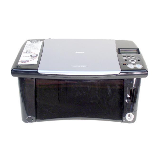
Chapter 1 1.3 Overview 1.3.1 External View 0004-4359 Exterior F-1-1 1. Tray extension Supports paper loaded in the multi-purpose tray. Pull it out before loading paper. 2. Multi-purpose tray Used to load paper. 3. Operation panel Displays the operating status of the machine. It is also used to change or check the settings of each function. For details, 4. - Page 28 Chapter 1 8. Platen glass Used to load a document to be processed. 9. Direct print port (for digital camera) digital camera or digital video camcorder to the machine when printing images directly from the camera. 10. Open button Press this button to open the paper output tray accommodated in the machine. The paper output tray will not open when the machine is placed on a tilted surface.
-
Page 29: 2Operation Panel
Chapter 1 15. Access lamp Lights when a memory card is inserted into the card slot. This lamp flashes while the machine is reading or writing data from/to the memory card. When the machine finishes reading or writing the card, the lamp shuts off. 16. - Page 30 Chapter 1 F-1-3 1. [ON/OFF] key Turns the machine ON and OFF. Before turning ON the machine, make sure the scan unit is closed. When turning ON and OFF, keep the key pressed for at least one second. 2. [SCAN] key Switches the machine to scan mode.
- Page 31 Chapter 1 9. [Color] key Starts color copying, scanning, or faxing. 10. [Black] key Starts black & white copying, scanning, or faxing. 11. [Stop/Reset] key Cancels operations and returns the machine to standby mode. 12. [Tone] key Switches temporarily to tone dialing. Also changes the mode when entering characters. 13.
-
Page 32: Consumables
0002-3979 Ink tanks Black:BCI-24 Black Color:BCI-24 Color NOTE: For optimum printing results and to avoid printing problems, Canon recommends that you only use the Canon Ink Tanks described in this guide. 1-17 Download Service Manual And Resetter Printer at http://printer1.blogspot.com... - Page 33 Download Service Manual And Resetter Printer at http://printer1.blogspot.com...
-
Page 34: Chapter 2 Technical Reference
Chapter 2 Technical Reference Download Service Manual And Resetter Printer at http://printer1.blogspot.com... - Page 35 Download Service Manual And Resetter Printer at http://printer1.blogspot.com...
- Page 36 Contents Contents 2.1 Component Layout..............................2-1 2.1.1 Printer Mechanical Section ..........................2-1 2.1.2 Electrical Layout ............................2-1 2.1.3 Sensor Layout ..............................2-2 2.2 Scanner Mechanism ............................2-4 2.2.1 Scanning Section Layout ..........................2-4 2.3 Printer Section..............................2-6 2.3.1 Printer Mechanical Section ..........................2-6 2.3.2 Carriage Section ............................2-6 2.3.3 Purge Section ...............................2-6 2.3.4 Paper Feed Section............................2-7 2.3.5 Ink Sensor ..............................2-7 2.3.6 Cleaning Mode and Suction Amount......................2-7...
- Page 37 Download Service Manual And Resetter Printer at http://printer1.blogspot.com...
-
Page 38: Component Layout
Chapter 2 2.1 Component Layout 2.1.1 Printer Mechanical Section 0003-2046 The printer's mechanical parts consist of the followings: F-2-1 2.1.2 Electrical Layout 0004-4414 The electrical parts are laid out as follows: - SPCNT board: Controls the entire facsimile machine. - OPCNT board: Detects keyboard operation and displays machine information. - Multi-card reader board: Interface with memory card. -
Page 39: 3Sensor Layout
Chapter 2 F-2-2 2.1.3 Sensor Layout 0002-5820 The sensors detecting document/paper-fedding condition or ink presence/absence are mounted. F-2-3 1. Carriage encoder film: Detects the state of carriage unit. Download Service Manual And Resetter Printer at http://printer1.blogspot.com... - Page 40 Chapter 2 2. Paper feed encoder film: Detects the state of paper feed roller. 3. Paper edge sensor: Detects the state of paper feeding and delivery. 4. Cover sensor: Detects the state of flatbed unit. 5. ASF sensor: Detects the state of ASF. Download Service Manual And Resetter Printer at http://printer1.blogspot.com...
-
Page 41: Scanner Mechanism
Chapter 2 2.2 Scanner Mechanism 2.2.1 Scanning Section Layout 0003-2048 The scanning section scans documents that are to be sent or copied. F-2-4 Names and functions of parts 1. CCD drive motor The CCD drive motoris used to drive the CCD. 2. - Page 42 Chapter 2 This white sheet is used as a whiteness reference when pre-scanning documents. Download Service Manual And Resetter Printer at http://printer1.blogspot.com...
-
Page 43: Printer Section
Chapter 2 2.3 Printer Section 2.3.1 Printer Mechanical Section 0002-0302 The printer's mechanical parts consist of the BJ cartridge section, carriage section, purge section, and paper feed section. Each part is explained below. F-2-5 2.3.2 Carriage Section 0002-0326 The carriage secures the printhead including 2 ink tanks in place. The carriage belt driven by the carriage motor (DC motor) moves the carriage horizontally back and forth across the paper. -
Page 44: 4Paper Feed Section
Chapter 2 2.3.4 Paper Feed Section 0002-0331 The paper feed section consists of the paper loading section, paper feed section, and paper eject section. 1) Paper Loading Section Paper is loaded automatically by the ASF (auto sheet feeder). The feeder is designed accommodate various sizes of paper (as large as LGL), picking up individual sheets and forwarding them to the feeding block. - Page 45 Chapter 2 - Manual cleaning/refreshing: Performed user operation - Unit delivery: Performed when scanner unit is close. T-2-1 Cleaning Mode Suction Condition Details Amount At delivery Suction when head is first 0.36(Bk) installed after factory shipment. 0.52(Color) Dot count suction When prescribed dot count since the last suctions reached (Bk/colors counted separately)
- Page 46 Chapter 2 Printhead refreshing * User operation (Bk/color/all colors) (all colors only) 1.50(Bk) * Driver operation 0.52(color) (Selectable from Bk, color, and all colors) *1: In case of time suction when 24 to 60 hours have elapsed since previous suction, the sequense will be complete after five suctions are performed after factory shipment.
- Page 47 Download Service Manual And Resetter Printer at http://printer1.blogspot.com...
-
Page 48: Chapter 3 Disassembly And Assembly
Chapter 3 Disassembly and Assembly Download Service Manual And Resetter Printer at http://printer1.blogspot.com... - Page 49 Download Service Manual And Resetter Printer at http://printer1.blogspot.com...
- Page 50 Contents Contents 3.1 Attention to be Paid During Assembly/Disassembly..................3-1 3.1.1 Safety Cautions ............................3-1 3.1.2 General Cautions............................3-2 3.1.3 Product-inherent Cautions..........................3-3 3.1.4 Caution when replacing the SPCNT board ....................3-4 3.1.5 Shipping the Main Unit..........................3-4 3.2 Assembly and Disassembly ..........................3-6 3.2.1 Disassembly/Assembly ..........................3-6 3.2.2 Basic Disassembly ............................3-6 3.2.3 Operation Panel Unit..........................3-12 3.2.4 Scanner Unit...............................3-13...
- Page 51 Download Service Manual And Resetter Printer at http://printer1.blogspot.com...
-
Page 52: Attention To Be Paid During Assembly/Disassembly
Chapter 3 3.1 Attention to be Paid During Assembly/Disassembly 3.1.1 Safety Cautions 0002-0114 Electrical shock In order to prevent any risk of electrical shock, always be sure to check that the power cord and modular jack have been removed. Also, remove all cables connecting to the computer. When conducting service that requires the main unit to be powered on, be sure to wear some kind of earthing, such as a wrist strap, etc. -
Page 53: 2General Cautions
Chapter 3 3.1.2 General Cautions 0002-0386 Damage due to electrostatic discharge This machine contains contact sensors and printed circuit boards that use ROMs, RAMs, custom chips and other electronic components that are vulnerable to damage by electrostatic discharge. Be careful to avoid any damage from electrostatic discharge when conducting service that requires disassembly. Static electricity warning Electrostatic discharge can destroy electronic components and alter electrical characteristics. -
Page 54: 3Product-Inherent Cautions
Chapter 3 of the purge unit or wire, the BJ cartridge nozzle may become blocked and the cartridge rendered unusable. Also, never use any other than the specified type of grease. Otherwise, plastic parts and rubber parts may melt or be deformed. -
Page 55: 4Caution When Replacing The Spcnt Board
Chapter 3 squirting for maintenance, in order to maintain the good printing quality of the BJ cartridge. The volume of ink absorbed is counted and these data stored in the EEPROM on the SPCNT board. Once the volume is judged to have reached 100%, the message "CHECK PRINTER"... - Page 56 Chapter 3 cord. If you leave the BJ cartridge (printhead) alone on its own, the ink can start to cake. Be sure to keep the BJ cartridge fitted in the carriage in the course of shipment. On the other hand, if the carriage is not fixed to its home position, it can move right/left during shipment, possibly importing stress on the paper feed encoder film.
-
Page 57: Assembly And Disassembly
Chapter 3 3.2 Assembly and Disassembly 3.2.1 Disassembly/Assembly 0002-0424 As a rule, refer to the Parts Catalog for instructions on how to disassemble and assemble the machine. The discussions that follow are limited to those components that are thought to require replacement relatively more often than others. - Page 58 Chapter 3 F-3-2 F-3-3 (4) Insert the precision screwdriver into the gap shown in the below photo. Detach the claw (d) and remove the right front cover. Download Service Manual And Resetter Printer at http://printer1.blogspot.com...
- Page 59 Chapter 3 Right Fromt Cover F-3-4 Reference The right front cover has 7 claws, and remaining claws will unhook by themselvs after detaching outer claws in step 3 and 4. Please refer to the below image for the position of claws (view of the reverse side). F-3-5 (5) Insert a precision flat bladed screwdriver in an upright posture in a narrow gap between the left front cover and Download Service Manual And Resetter Printer at http://printer1.blogspot.com...
- Page 60 Chapter 3 the left side cover. Exert an outward pressure by twisting the screwdriver to detach the claw (f). Detaich 3 claws (g) in descending order and remove the left front cover. Left Front Cover F-3-6 Reference The left front cover has 8 claws. The remaining nails will unhook by themselves after detaching outer claws in step 5.
- Page 61 Chapter 3 the button by pulling it out from the machine. Open Button F-3-8 (7) Remove 3 screws (e) (one in the front and two in the back), and then remove the right side cover. Righr Side Cover F-3-9 3-10 Download Service Manual And Resetter Printer at http://printer1.blogspot.com...
- Page 62 Chapter 3 The side cover has a claw inside. So lifting the side cover will make it easier to detach it from the main unit. The side cover works as a bearing of the scanner unit. Please be careful not to get your finger caught between the scanner unit and the side cover when removing the side cover.
-
Page 63: 3Operation Panel Unit
Chapter 3 Left Side Cover F-3-11 3.2.3 Operation Panel Unit 0002-5257 (1) Remove 6 claws (a) and then remove the operation panel cover. (2) Remove 4 screws (b). (3) Remove Connector J1 from the operation panel unit, and then remove the operation panel unit from main unit. -
Page 64: 4Scanner Unit
Chapter 3 3.2.4 Scanner Unit 0002-5262 (1) Perform step 1 thorugh step 3 in the Basic Disassembly, and then remove the right front cover. (2) Remove the screw (a) and then remove a grounding cable. (3) Remove Connector JCCD1, JCCD2, JPANEL1 from the SPCNT Board. SPCNT Board F-3-13 (4) Remove the scanner unit from the main unit. -
Page 65: 5Ncu Board, Modular Board
Chapter 3 3.2.5 NCU Board, Modular Board 0004-2911 (1) Remove 5 screws (a) and then remove the rear cover. Rear cover Multi-purpose tray F-3-15 (2) Remove the claw (b) and then remove a speaker from the rear cover. 3-14 Download Service Manual And Resetter Printer at http://printer1.blogspot.com... - Page 66 Chapter 3 Speaker F-3-16 (3) Remove all cables connected to NCU Board. (4) Remove two screws (c) and then remove NCU Board. (5) Remove connector J3 from the modular board. (6) Remove 2 screws (d) and then remove the modular board. Moduler Board NCU Board F-3-17...
-
Page 67: 6Spcnt Board
Chapter 3 3.2.6 SPCNT Board 0002-5266 (1) Perform the Basic Disassembly procedures. (2) MP390: Remove NCU and the modular board. (3) Perform step 1 through step 4 of the disassembly procedures of the scanner unit. Then remove the scanner unit from the main unit. (4) Remove the inner cover from the middle frame. -
Page 68: 7Modem Board
Chapter 3 Multi-Card Reader Frame SPCNT Board F-3-19 (10) Remove 3 screws (c) and then remove the SPCNT Board together with its frame from the main unit. SPCNT Board Frame F-3-20 3.2.7 Modem Board 0004-2908 (1) Remove the SPCNT Board from the main unit. (2) Remove 3 claws (a). -
Page 69: Print & Asf Unit
Chapter 3 F-3-21 (3) Remove Connector JMODEM1 and then remove the modem board. 3.2.8 Print & ASF Unit 0002-5279 (1) Perfom the bais disassembly procedures. (2) MP390: Remove NCU and the modular board. (3) Remove the scanner unit. (4) Remove the inner cover from the middle frame. (5) Remove Connector JHEAD1, JHEAD0, JEXIT1, and JPSU1 from the SPCNT board. - Page 70 Chapter 3 Inner Cover Middle Frame SPCNT Board F-3-22 (7) Remove 3 screws (b) and then remove the SPCNT board together with the board frame. SPCNT Board Frame F-3-23 (8) Remove Connector JTRY1 from the SENS board. (9) Remove 3 screws (c) and then remove the printer and ASF unit from the main unit by lifting them. 3-19 Download Service Manual And Resetter Printer at http://printer1.blogspot.com...
-
Page 71: 9Power Supply Unit
Chapter 3 Print & ASF Unit F-3-24 3.2.9 Power Supply Unit 0002-5288 (1) Perform the basic disassembly procedures. (2) MP390: Remove NCU and the modular board. (3) Remove the scanner unit. (4) Remove Print & ASF unit. (5) Remove the screw (a) and then remove the Power supply unit cover. (6) Remove the screw (b) and then remove the Power connector cover. - Page 72 Chapter 3 (7) Remove the screw (c) and then remove the Power supply unit. F-3-26 Removing the Power supply unit (MP390 only) Please make sure to attach the Power supply unit to the main unit only after connecting a grounding cable to the unit. If a grounding cable is connected to the Power supply unit after the Power supply unit is attached to the main unit, it may damage the Power supply unit with electrical stress.
- Page 73 Download Service Manual And Resetter Printer at http://printer1.blogspot.com...
-
Page 74: Maintenance
Chapter 4 Maintenance Download Service Manual And Resetter Printer at http://printer1.blogspot.com... - Page 75 Download Service Manual And Resetter Printer at http://printer1.blogspot.com...
- Page 76 Contents Contents 4.1 Maintenance ................................4-1 4.1.1 Consumables ..............................4-1 4.1.2 Cleaning ...............................4-1 4.1.3 Periodic Inspection............................4-1 4.1.4 Periodic Replacement Parts .........................4-2 4.1.5 Adjustment Items ............................4-2 4.1.6 General Tools ...............................4-2 4.1.7 Special Tools..............................4-2 4.2 How to Clean Parts .............................4-4 4.2.1 How to Clean Parts ............................4-4 4.2.2 Exterior.................................4-4 4.2.3 Scanning Unit...............................4-4 4.2.4 Printer................................4-5...
- Page 77 Download Service Manual And Resetter Printer at http://printer1.blogspot.com...
-
Page 78: 3Periodic Inspection
Chapter 4 4.1 Maintenance 4.1.1 Consumables 0002-0433 T-4-1 Level Consumable When User Ink tank When ink in the ink tank runs (BCI-24Black / out. BCI-24Color) Service Person BJ cartridge Uneven printing even after performing head cleaning several times with ink remained in the tank. -
Page 79: 4Periodic Replacement Parts
Chapter 4 4.1.4 Periodic Replacement Parts 0002-0476 None 4.1.5 Adjustment Items 0002-5585 The following adjustments must be made on this fax. T-4-3 Item Indication Printhead Position Adjustment When the vertical lines shift during Bi- directional printing. 4.1.6 General Tools 0002-0583 T-4-4 Tool... - Page 80 Chapter 4 Tool Part No. Grease (PG-641) Apply to specified CK-0562 parts Grease (IF-20) Apply to specified CK-8006 parts Download Service Manual And Resetter Printer at http://printer1.blogspot.com...
-
Page 81: How To Clean Parts
Chapter 4 4.2 How to Clean Parts 4.2.1 How to Clean Parts 0002-0504 NOTE: If the parts above are very dirty, wipe with a cloth moistened with IPA (isopropyl alcohol). Precautions when Using IPA When cleaning wit IPA, take care to prevent the IPA from splashing high-temperature parts. If IPA splashes high- temperature parts, leave for at least three minutes to allow the IPA to evaporate. -
Page 82: Printer
Chapter 4 F-4-1 A: Document Cover B: Document Glass 4.2.4 Printer 0002-2366 Cleaning the roller Remove all the media from the multi-purpose tray, and then press the [User Mode] key. Select [MAINTENANCE] by pressing cursor keys. Select [ROLLER CLEANING] by pressing cursor keys, and then press the [Set] key. Repeat this procedure twice after the roller cleaning is complete. -
Page 83: Service Switches
Chapter 4 4.3 Service Switches 4.3.1 Hardware Switches 0002-0525 There is no service hardware switche on the Circuit board. 4.3.2 Service Data Setting 0002-0528 Service data can be checked and changed with items on display menus. The effective SSSWs/parameters and their default values in this fax machine are shown in Service Data Setting. - Page 84 Chapter 4 #8 CLEAR (Data initialization mode) Various data is initialized by selecting one of these setting items. There is a setting item for checking/inputting the total number of pages printed and total number of pages scanned by this fax. #9 ROM (ROM management) ROM data such as the version number and checksum are displayed.
-
Page 85: 3Service Data Flowchart
Chapter 4 4.3.3 Service Data Flowchart 0004-3250 Service Data #1 SSSW Error management SW01 – – – – – (Service soft switch setting) NETWORK connection condition SW02 – – – – – – – memory clear list setting Echo solution setting SW03 –... - Page 86 Chapter 4 F-4-2 The switches marked "-" are not used. Do not change their settings. #2 MENU Not used (Menu switch settings) Not used Not used Not used NL equalizer setting DIAL Line monitor setting SERVICEMAN Transmission level setting 10 (-10dBm) (8~15) 3429 (baud) V.34 Baud rate...
- Page 87 Chapter 4 #3 NUMERIC Param. (Numeric parameter settings) Default Range Not used 10 (10%) (1~ 99) RTN signal transmission condition (1) 15 (15 lines) (2~ 99) RTN signal transmission condition (2) 12 (12 times) (1~ 99) RTN signal transmission condition (3) Not used Not used Not used...
- Page 88 Chapter 4 No. 01, 05 to 08, 012 to 14, 27 to 30 are not used. Do not change their settings. #3 NUMERIC PARAM. (Numeric parameter settings) The relationship between the settings and the detection levels is as follows: Parameter 24 0: Not used 1: Not used 2: Not used 3: Not used 4: Not used 5: -8 dBm 6: -9 dBm 7: -10 dBm 8: -11 dBm 9: -12 dBm 10: -13 dBm 11: -14 dBm 12: -15 dBm 13: -16 dBm 14: -17 dBm...
- Page 89 Chapter 4 4-12 Download Service Manual And Resetter Printer at http://printer1.blogspot.com...
- Page 90 Chapter 4 #4 NCU 1.TONE/PULSE (NCU settings) 2.DIAL TONE 3.2nd DIAL TONE 4.BUSY TONE 0 5.BUSY TONE 1 6.REORDER TONE 7.MULTI 8.AUTO RX 9.CNG DETECT 10.SPECIAL 11.RKEY 12.PBX DIAL TONE 13.PBX BUSY TONE #5 TYPE U.S.A. (Type setting) EUROPE U. K. SWEDEN SWISS AUSTRIA...
- Page 91 Chapter 4 F-4-5 #4 NCU (NCU settings) The values of these items are all set to match a specific nation's communications standards by the #5 TYPE setting. Do not change these setting. #6 GENESIS (UHQ) 1.Bit SW (Genesis function settings) 2.SLICE 3.GAMMA #1 SSSW...
- Page 92 Chapter 4 #6 GENESIS (UHQ function settings) Tampering with this setting may cause the scanned image quality to deteriorate. Do not change these settings. #8 CLEAR Dialling data initialization User data and service data #1 t USER SW (Data initialization mode initialization settings) User data and service data #1 t...
-
Page 93: New Sssws/Parameters Added To This Model
Chapter 4 4.4 New SSSWs/Parameters Added to This Model 4.4.1 Service Data 0002-0681 SSSW (Service Soft Switch settings) The items registered and set by each of these switches comprise 8-bit switches. The figure below shows which numbers are assigned to which bits. Each bits has a value of either 0 or 1. SW01 F-4-8 Refer to the service data menu for the details of the service switches and the initial setup values of this machine. -
Page 94: User Report Output Functions
Chapter 4 4.5 User Report Output Functions 4.5.1 User report output functions 0004-5270 The machine can output user reports manually by user operation, or automatically, according to user data settings. a) Manual output of reports by user operation T-4-6 Report type Operations Activity report Press the [Additional Function] key, and then... - Page 95 Chapter 4 WLD-XX-XX /X.XX F-4-10 A: Printer ROM version B: MAIN-ROM-version c) Reports output automatically Memory clear report The machine automatically outputs a memory clear report when the power is turned on after a power cut. F-4-11 TX/RX NO : Indicates four digits of the transaction number MODE : Indicates, TRANSMIT, MEMORY RX etc.
-
Page 96: Wiring Diagram
Chapter 4 4.6 Wiring Diagram 4.6.1 Wiring Diagram 0005-4763 Scanner unit Carriage unit Operation panel Flat Flat Flat cable cable cable 1---12 1----22 1-------27 Cover sensor JCCD1 JPANEL1 JHEAD1 1--------27 JHEAD2 SPCNT board Power supply unit JEXT1 1-------28 Camera NCU board Modem board To Sensor board JSPK1 board... - Page 97 Download Service Manual And Resetter Printer at http://printer1.blogspot.com...
-
Page 98: Chapter 5 Troubleshooting
Chapter 5 Troubleshootin Download Service Manual And Resetter Printer at http://printer1.blogspot.com... - Page 99 Download Service Manual And Resetter Printer at http://printer1.blogspot.com...
- Page 100 Contents Contents 5.1 Troubleshooting Index ............................5-1 5.1.1 Troubleshooting Index ..........................5-1 5.2 Errors Shown on the Display ..........................5-3 5.2.1 User Error Message............................5-3 5.3 Error Code................................5-8 5.3.1 ERROR CODE LIST ...........................5-8 5.3.2 New Error Codes and Recovery methods ....................5-13 5.4 Errors not Shown on the Display ........................5-15 5.4.1 General Errors ............................5-15 5.4.2 Printing problem ............................5-15 5.4.3 Scanning Problems.............................5-17...
- Page 101 Download Service Manual And Resetter Printer at http://printer1.blogspot.com...
-
Page 102: Troubleshooting Index
Chapter 5 5.1 Troubleshooting Index 5.1.1 Troubleshooting Index 0002-1612 For troubleshooting, use the troubleshooting index below to investigate the cause of the problem and refer to the specified page for countermeasures. Problem Errors shown on the display (Evaluation criteria: Look at the unit in question.) The error message can be checked. - Page 103 Chapter 5 Download Service Manual And Resetter Printer at http://printer1.blogspot.com...
-
Page 104: Errors Shown On The Display
Chapter 5 5.2 Errors Shown on the Display 5.2.1 User Error Message 0004-3247 Look for the applicable error message and execute the appropriate countermeasures. "BLACK INK LOW" Cause: The ink level in the black ink tank is low. Solution: Replace the black ink tank. If the machine stops printing when copying or photo printing, you can continue printing by pressing the [Set] key. - Page 105 Chapter 5 Solution: Wait until the card slot is no longer being used by the computer. "CARD READER ERROR" Cause: Thre is a problem with the card slot. Solution: (1) Switch to another mode or turn the machine OFF and ON. (2) Check the connection between the multi-card board and the SPCNT board.
- Page 106 Chapter 5 Cause: Carriage motor does not work. Solution: (1) Switch power OFF/ON. (2) Replace the carriage motor. Cause: The position of the carriage cannot be detected (due to smears on the carriage encoder film or the SPCNT board failure). Solution: (1) Switch power OFF/ON.
- Page 107 Chapter 5 stops printing when copying or photo printing, you can continue printing by pressing the [Set] key. However, note that ink may run out. If print quality deteriorates or the printout is blank, replace the ink tank. "COVER OPEN" Cause: You opened the flatbed ass'y during an operation.
- Page 108 Chapter 5 "PUT IN CARTRIDGE" Cause: The printhead is not set. Solution: Set the printhead. "WASTED INK NEAR FULL" Cause: The waste ink tank (which holds the ink used for print head cleaning) is nearly full. Solution: If "CHECK PRINTER" message is displayed, refer to Cause and Solution of the error code ##343 and replace the waste ink tank.
-
Page 109: Error Code
Chapter 5 5.3 Error Code 5.3.1 ERROR CODE LIST 0002-0964 The error codes that have newly been added starting with the product are identified by the notation "new" those error codes for which remedies unique to the product are offered are identified by the notation "UNQ (UNIQUE)." User error code T-5-1 Tx or Rx... - Page 110 Chapter 5 Tx or Rx Definition ##103 [RX] EOL cannot be detected for 5 sec (15 sec if CBT) ##104 [TX] RTN or PIN has been received ##106 [RX] The procedure singal cannot be received for 6 sec while in wait ##107 [RX] The transmitting machine cannot be use fallback...
- Page 111 Chapter 5 Tx or Rx Definition ##287 [TX] DCN has been received after transmitting MPS After transmitting EOP, a signal other than PIN, PIP, MCF, RTP, or RTN ##288 [TX] was received After transmitting EOM, a signal other than PIN,PIP,MCF, RTP, or RTN ##289 [TX] was received...
- Page 112 Chapter 5 Tx or Rx Definition In V.34 reception, the procedure fails to move from phase 2 to phase 3 ##673 [RX] and later, causing a T1 time-over condition In V.34 transmission, the procedure fails to move from phase 3 or phase ##674 [TX] 4 to a control channel or later, causing a T1 time-over condition...
- Page 113 Chapter 5 Tx or Rx Definition In ECM transmission, no significant signal can be received after transmission of PPS-EOP, and the allowed number of procedure signal ##765 [TX] re-transmissions was exceeded ##767 [TX] In ECM transmission, DCN was received after transmission of PPS-EOP In ECM transmission, the allowed number of procedure signal re- transmissions was exceeded or a T5 time-over (60 sec) condition ##768...
-
Page 114: 2New Error Codes And Recovery Methods
Chapter 5 Tx or Rx Definition In ECM transmission, ERR was received after transmission of EOR- ##784 [TX] In ECM transmission, no significant signal can be received after transmission of EOR-EOP, and the allowed number of procedure signal ##785 [TX] re-transmissions was exceeded In ECM transmission, DCN was received after transmission of EOR- ##787... - Page 115 Chapter 5 ##352 Printer control EEPROM head information error Cause: The EEPROM for printer control is faulty. Solution: (1) Turn off and then on the power. (2) Turn off the power, and replace the printhead. (3) Replace the SPCNT board. NOTE: In the presence of ##352, the carriage unit will not move to printhead replacement position even when the inner cover is opened.
-
Page 116: Errors Not Shown On The Display
Chapter 5 5.4 Errors not Shown on the Display 5.4.1 General Errors 0002-1688 The unit does not power on. (1) Check the power cord connection. (2) Check the connection between the PCNT board (JPSU1) and power supply unit. (3) Check the power supply unit's fuse (F1) (4) Replace the power supply unit. - Page 117 Chapter 5 The printing operation is abnormal. Nothing prints. (1) Remove the BJ cartridge and re-install it. (2) Execute cleaning five times, and try printing again. (3) Replace the BJ cartridge. (4) Replace the ink tank. (5) Replace the purge unit. (6) Check the connection between carriage ribbon cable and SPCNT board (JHEAD1, JHEAD0).
-
Page 118: 3Scanning Problems
Chapter 5 Missing dots Unstable printing Splashed dots F-5-1 Blotched appear Blank ink appear (1) Remove and reinstall the printhead. (2) Perform printhead cleaning, and visually check the test print for non-discharge of ink from nozzle. (3) Perform head-refreshing, and visually check the test print for non-discharge of ink from nozzle. (4) Replace the appropriate ink tank. -
Page 119: 4Memory Card Problem
Chapter 5 (1) Check the connection between the CCD and SPCNT board (JCCD1). (2) Replace the scanner unit. (3) Replace the SPCNT board. The image has vertical stripes. (1) Clean the Document glass. (2) Check the connection between the CCD and SPCNT board (JCCD1). (3) Replace the scanner unit. -
Page 120: Test Mode Function Problems
Chapter 5 5.5 Test Mode Function Problems 5.5.1 Faulty Operation Panel Test 0002-5806 The LED panel does not display correctly. (1) Check the connection between the OPECNT board (J1) and the SPCNT board (JPANEL1). (2) Replace the operation panel unit. (3) Replace the SPCNT board. -
Page 121: Processing Communication Problems
Chapter 5 5.6 Processing Communication Problems 5.6.1 Initial identification of problems 0004-2797 Since the facsimile must transmit picture information, a transmitter, a receiver and telephone lines are required for this purpose. Transmissions may cause problems if one or more of the there is poor. Communication trouble Your... -
Page 122: 2Procedures For Processing Communication Problems
Chapter 5 Start Does an error Errors show on the display. appear on the error massage display? error code Is copying General error being done? Do copying Is copy Test print Printing problem picture OK? Communication problems Scanning problem exist. Carry out the procedures. F-5-4 5.6.2 Procedures for processing communication problems 0004-2875... - Page 123 To quicken the resolving of the problem, report the information listed in (1) above. * Procedures for processing communication problems with Canon facsimile. The process for carrying out communications at three points as shown in the figure.
- Page 124 Chapter 5 Trouble FAX:A FAX:B FAX:C Start A: Your customer's facsimile B: Facsimile of other communication party C: Facsimile for check in the same region. (C should be the same model of facsimile as A.) Transmission Transmission or reception? Reception Check A.
- Page 125 Chapter 5 Trouble Start FAX:A FAX:B Is the group the same? (G1/G2/G3) FAX:C FAX:D Is there the A: Your customer's facsimile similar B: Facsimile of other communication Unable to trouble case? party receive C: Facsimile for check in the same region.
-
Page 126: Test Functions
Chapter 5 5.7 Test Functions 5.7.1 Test Mode Overviw 0004-3256 Test mode can be executed by following the menu items from the display. a) DRAM test Writes data to DRAM image storage areas and read that data to check operations. b) PRINT test Prints test patterns within the print area. - Page 127 Chapter 5 TEST MODE indicates that these are not used in the field. [1] D-RAM [2] CS [1] ADJ LED TIME [2] CD READ [3] DISP LEDTIME [4] REG LEDTIME [5] SHADING [6] FB READ [3] PRINT [1] CLR PTN1 [2] CLR PTN1 [3] LF CHK [4] COMET...
-
Page 128: 3Dram Tests
Chapter 5 5.7.3 DRAM Tests 0004-4269 Pressing the numeric key 1 or key from the test mode menu selects the D-RAM tests. D-RAM Test 1 writes data to the entire D-RAM region and reads it out to check that operations are correct. DRAM Test 2 just reads data at high speed. -
Page 129: 5Faculty Tests
Chapter 5 Check for any vertical or horizontal white stripes on the black squares. Also, check that all the squares have straight edges on all four sides. F-5-9 NOTE: If the print test is normal, make a copy of a document. If the copy is faulty, the reading section is faulty. Please do not select the following menu: 3-1: CLR PTN1, 3-2: CLR PTN2 If a mistake is made and these menus are selected, the value of #7 PRINTER #5. - Page 130 Chapter 5 a) Sensor tests Select the sensor test from the faculty test menu by pressing the numeric key 3 or keys. In this test, you can check the status of each sensor of this fax in item 1 on the display. You can also check if sensors that use actuators and microswitch are operating correctly by moving the actuator or microswitch.
- Page 131 Chapter 5 the test. b-3) Operation key test Press the Start key to select the Operation key test after the LED lamp test is complete. In this test, you press the key corresponding to the displayed character to put it out. The table giving the correspondence between the characters and the keys is shown below.
- Page 132 Chapter 5 6-7: PANEL Press Color start key H Pattern display Press Color start key ALL LCD dots displayed Press Color start key _ pattern display Press Color start key Every time pressing color start key, 6-7: PANEL a LED lamp is turned on one by one. LED TEST Continue pressing color start key until every LED lamp is tested.
-
Page 133: 6Printer Tests
Chapter 5 CNG are detected from the modular jack, the display changes from OFF to ON and the received frequency is displayed. c-2) Test Menu 2 Test Menu 2 is selected by pressing the numeric key 2 or key and key from the Line Detect menu. -
Page 134: 7Modem, Ncu Tests
Chapter 5 5.7.7 MODEM, NCU Tests 0004-3320 The Modem and NCU Test menu is selected by pressing the numeric key 4 or from the test mode menu. These tests test modem and NCU transmission and reception. The modem tests check whether signals are sent correctly from the modem by comparing the sound of the signals from the speaker with the sounds from a normal modem. - Page 135 Chapter 5 b) G3 signal transmission test The G3 signal transmission test menu is selected by pressing the numeric key 4 or keys from the MODEM NCU test menu. The G3 signals below are sent from the modem using the modular jack and the speaker. The frequency can be changed with the numeric key.
- Page 136 Chapter 5 Numeric key Baud rate 2743 baud 2400 baud T-5-10 Numeric key SPEED 33.6 kbps 31.2 kbps 28.8 kbps 26.4 kbps 24.0 kbps 21.6 kbps 19.2 kbps 16.8 kbps 14.4 kbps 12.0 kbps 9.6 kbps 7.2 kbps 4.8 kbps 2.4 kbps 5-35 Download Service Manual And Resetter Printer at http://printer1.blogspot.com...
- Page 137 Download Service Manual And Resetter Printer at http://printer1.blogspot.com...
-
Page 138: Chapter 6 Appendix
Chapter 6 Appendix Download Service Manual And Resetter Printer at http://printer1.blogspot.com... - Page 139 Download Service Manual And Resetter Printer at http://printer1.blogspot.com...
- Page 140 Contents Contents 6.1 Main Body................................6-1 6.1.1 Installation..............................6-1 6.1.2 Checking Operation .............................6-1 6.2 User Data Flow ..............................6-3 6.2.1 User Mode Settings ............................6-3 6.2.2 Fax Mode Settings ............................6-6 Download Service Manual And Resetter Printer at http://printer1.blogspot.com...
- Page 141 Download Service Manual And Resetter Printer at http://printer1.blogspot.com...
-
Page 142: Main Body
Chapter 6 6.1 Main Body 6.1.1 Installation 0002-0817 Reference: This machine is to be installed by a user, so this service manual contains only a briefing of installation procedures. Please refer to the Set-up Sheet enclosed in the package of the machine for more details. * Check an installation space. - Page 143 Chapter 6 What to do when trouble occurs Very rarely, during use, the display may go out, all the buttons may stop working, or some other trouble may occur because of strong electrical noise or a large amount of static. If such trouble occurs, execute 'All clear'. Download Service Manual And Resetter Printer at http://printer1.blogspot.com...
-
Page 144: User Data Flow
Chapter 6 6.2 User Data Flow 6.2.1 User Mode Settings 0004-3904 Additional Fanction 1.FAX SETTINGS 1.RECEIVE MODE FAX/TEL AUTO SW FAX ONLY MODE DRPD MANUAL MODE ANS. MACHINE MODE 2.MEMORY REFERENCE ACTIVETY REPORT 3.REPORTS/LISTS DIRECTORY DIAL USER DATA LIST DOC. MEMORY LIST 4.TEL# REGISTRATION 5.USER SETTINGS 1.DATE/TIME SETTING... - Page 145 Chapter 6 6.TX SETTINGS 1.ECM TX 2.PAUSE TIME 2 SEC.(1 3.AUTO REDIAL 4.TX START SPEED 33600 bps 14400 bps 9600 bps 7200 bps 4800 bps 2400 bps 5.TX REPORT PRINT ERROR ONLY OUTPUT YES OUTPUT NO 1.ECM RX 7.RX SETTING 2.FAX/TEL AUTO SW 8 SEC.(0 1.RING START TIME...
- Page 146 Chapter 6 F-6-3 Download Service Manual And Resetter Printer at http://printer1.blogspot.com...
-
Page 147: 2Fax Mode Settings
Chapter 6 6.2.2 Fax Mode Settings 0004-3907 Press the FAX button, and the Menu button 1.PAPER SELECT SIZE 4" x 6" 5"x 7" TYPE PLAIN GLOSSY HIGH RES. TRANS. PHOTO PRO PHOTO PLUS OTHER 2.SCAN CONTRAST 3LEVEL (- LIGHT + DARK) 3.FAX RESOLUTION STANDARD FINE... - Page 148 Jan 7 2004 Download Service Manual And Resetter Printer at http://printer1.blogspot.com...
- Page 149 Download Service Manual And Resetter Printer at http://printer1.blogspot.com...