
Related Manuals for Honeywell Prestige IAQ YTHX9421


Summary of Contents for Honeywell Prestige IAQ YTHX9421
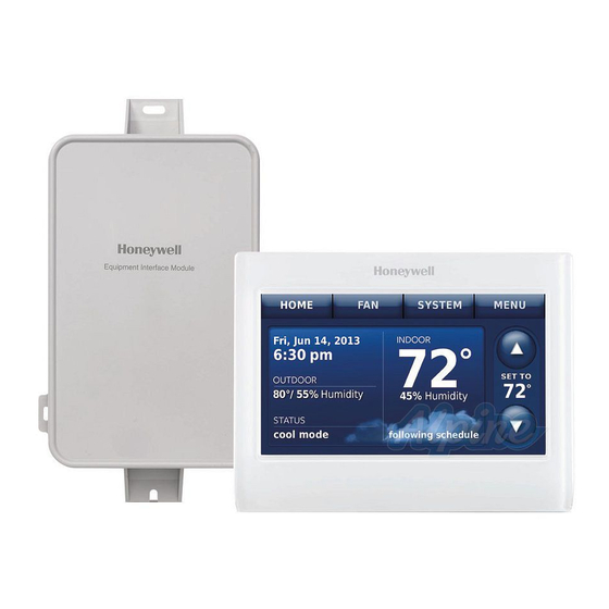
- Page 1 ® Prestige with Equipment Interface Module Installation Guide RedLINK to Equipment Interface Module 2 Wires for Power RedLINK to TrueZONE Wireless Adapter 2 Wires for Power...
- Page 2 Reference to key features Current display. Button pressed in signifies current display Mode control buttons. Use to change settings for Fan or System Heat/Cool. Menu. Select options to: set schedules, view equipment status, change IAQ settings, access installer options*, etc. Current schedule.
- Page 3 Installing the equipment interface module (EIM) NOTE: If an EIM is mounted inside a metal cabinet, it is recommended to use a THM4000R1000 Wireless Adapter for extended wireless range. Mount the Wireless Adapter outside the metal cabinet and connect to the ABCD terminals at the EIM.
- Page 4 Terminal Designations Conventional System Heat Pump Terminal Description Terminal Description Universal relay for humidification, Universal relay for humidification, U1 / U1** dehumidification, ventilation, or U1 / U1** dehumidification, ventilation, or U2 / U2** a stage of heating/cooling. U U2 / U2** a stage of heating/cooling.
- Page 5 Wiring humidification, dehumidification and ventilation Typical hookup of powered humidifier Typical hookup of non-powered humidifier NON-POWERED POWERED HUMIDFIER HUMIDIFIER FIELD INSTALLED JUMPER BETWEEN R AND U1 24 VAC Typical hookup of non-powered Typical hookup of powered ventilation ventilation NON-POWERED POWERED VENTILATOR VENTILATOR FIELD INSTALLED JUMPER BETWEEN R AND U1 24 VAC...
- Page 6 Installing the thermostat Thermostat (back view) 2.1 Separate wallplate from thermostat. 1324 Wallplate (back view) 2.2 Mount wallplate as shown. Mount new wallplate using screws and anchors included Wallplate with the thermostat. Drill 3/16-in holes for drywall. Drill 7/32-in holes for plaster. Wallplate 2.3 Connect power to thermostat.
- Page 7 Wallplate 2.5 Mount thermostat on wallplate. Align thermostat to wallplate and snap into place. Thermostat Powering optional RedLINK accessories 3.1 Install batteries in RedLINK accessories. • Portable Comfort Control • Wireless Outdoor Sensor* • Wireless Indoor Sensor* • Wireless Entry/Exit Remote* • Wireless Vent and Filter Boost Remote* * Requires setup.
- Page 8 Performing initial setup Initial setup options define the type of system you are installing: • Residential or commercial • Non-zoned or zoned • Used with or without an Equipment Interface Module (THM5421) • Used with or without the TrueZONE Wireless Adapter (THM4000) 4.1 Follow prompts on the screen to select appropriate options. NOTE: If you are connecting the thermostat to the TrueZONE Wireless...
- Page 9 4.3 When you see the prompt Do you have RedLINK accessories to or No. connect? Touch • If you select Yes, you will be prompted to Press Connect on all new accessories. Continue to Step 4.4. • If you select No, continue to Step 4.5. 4.4 Connect each RedLINK accessory.
- Page 10 Finding your password (Date Code) • To add or remove RedLINK accessories • To make changes to Installer Setup • To perform Installer Test • To view Data Logs Thermostat (back view) Finding your password 1324 You can find the Date Code on the back of the thermostat, or Password (Date Code)
- Page 11 Linking RedLINK accessories to the thermostat 1 Touch Menu. Installer Options. 2 Select Installer Op�ons 3 Enter password (date code) and touch Done. Done Wireless Device Manager. 4 Select Wireless Device Manager Add Device 5 Select to display the Add Device screen.
- Page 12 Making changes to Installer Setup and performing Installer Test Follow these steps to set system options after initial installation. NOTE: Use a USB device to save set up time. See page 14. 1 Touch Menu. Installer Options. 2 Select Installer Op�ons 3 Enter password (date code) and touch Done.
- Page 13 Mounting an indoor sensor 1 Remove the wallplate and mount it 4 to 6 feet above the floor on an interior wall. Drill 3/16-inch holes for drywall, 7/32-inch for plaster. 2 Attach sensor securely to wallplate as shown. Indoor sensor operation Temperature control The thermostat can be set to respond to its internal temperature sensor, or to an optional...
- Page 14 Interactions Log and Performance Logs) to a USB device - then view them on your computer. Also use the USB device to upgrade the thermostat software. • Visit http://thermostatsetup.honeywell.com to enter your dealer information and contractor logo or load new thermostat software.
- Page 15 Specifications and replacement parts Operating Ambient Temperature Thermostat: 32 to 120° F (0 to 48.9° C) Portable Comfort Control: 32 to 120° F (0 to 48.9° C) Wireless Outdoor Sensor: -40 to 140° F (-40 to 60° C) Wireless Indoor Sensor: 0 to 120° F (-17.8 to 48.9° C) -For Optimal Battery Life: 35 to 114°...
- Page 16 (residential installation) 1-888-245-1051 (commecial installation) Scan for more information Automation and Control Systems Honeywell International Inc. 1985 Douglas Drive North Golden Valley, MN 55422 http://customer.honeywell.com ® U.S. Registered Trademark. © 2012 Honeywell International Inc. 69-2739—01 M.S. 11-12 69-2739-01 Printed in U.S.A.