Yamaha DVX-1000 Service Manual
Dvd home theater sound system (dvd receiver/subwoofer/speakers)
Hide thumbs
Also See for DVX-1000:
- Owner's manual (120 pages) ,
- Owner's manual (484 pages) ,
- Owner's manual (120 pages)
Table of Contents
Advertisement
Quick Links
Download this manual
See also:
Owner's Manual
DVD RECEIVER/SUBWOOFER/SPEAKERS
DVR-1000/NX-SW1000/NX-P1000
• The DVX-1000 consists of the DVR-1000, NX-SW1000 and NX-P1000.
• When accepting a repair order from the user, it is recommended to receive DVR-1000, NX-SW1000
and NX-P1000 as a set for the repair work.
• DVX-1000は、DVR-1000、NX-SW1000 および NX-P1000 で構成されています。
• 修理依頼を受ける際、DVR-1000、NX-SW1000 および NX-P1000 を一緒にお預かりすることを推奨します。
This manual has been provided for the use of authorized YAMAHA Retailers and their service personnel.
It has been assumed that basic service procedures inherent to the industry, and more specifically YAMAHA Products, are already
known and understood by the users, and have therefore not been restated.
WARNING:
IMPORTANT:
The data provided is believed to be accurate and applicable to the unit(s) indicated on the cover. The research, engineering, and service
departments of YAMAHA are continually striving to improve YAMAHA products. Modifications are, therefore, inevitable and
specifications are subject to change without notice or obligation to retrofit. Should any discrepancy appear to exist, please contact the
distributor's Service Division.
WARNING:
IMPORTANT:
CONTENTS
TO SERVICE PERSONNEL ..................................... 2-3
LOCALE MANAGEMENT INFORMATION ................. 4
SYSTEM COMPOSITION / システム構成 .................... 5
FRONT PANELS ....................................................... 5-6
REAR PANELS ....................................................... 7-10
REMOTE CONTROL PANEL ..................................... 11
SPECIFICATIONS / 参考仕様 .............................. 12-14
INTERNAL VIEW ........................................................ 15
DISASSEMBLY PROCEDURES / 分解手順 ........ 16-20
プロテクション情報の表示 .................................... 21-22
1 0 1 0 8 3
DVD HOME THEATER SOUND SYSTEM
IMPORTANT NOTICE
Failure to follow appropriate service and safety procedures when servicing this product may result in personal
injury, destruction of expensive components, and failure of the product to perform as specified. For these reasons,
we advise all YAMAHA product owners that any service required should be performed by an authorized YAMAHA
Retailer or the appointed service representative.
The presentation or sale of this manual to any individual or firm does not constitute authorization, certification or
recognition of any applicable technical capabilities, or establish a principle-agent relationship of any form.
Static discharges can destroy expensive components. Discharge any static electricity your body may have
accumulated by grounding yourself to the ground buss in the unit (heavy gauge black wires connect to this buss).
Turn the unit OFF during disassembly and part replacement. Recheck all work before you apply power to the unit.
© 2008 YAMAHA CORPORATION. All rights reserved.
This manual is copyrighted by YAMAHA and may not be copied or
redistributed either in print or electronically without permission.
SERVICE MANUAL
SERVICE MANUAL
自己診断機能 ......................................................... 23-30
AMP ADJUSTMENT ................................................... 31
IC DATA ................................................................ 32-40
BLOCK DIAGRAMS ............................................. 41-43
PIN CONNECTION DIAGRAM ................................... 44
PRINTED CIRCUIT BOARDS .............................. 45-58
SCHEMATIC DIAGRAMS .................................... 59-74
REPLACEMENT PARTS LIST ............................. 75-85
REMOTE CONTROL .................................................. 86
DVX-1000
'08.03
Advertisement
Table of Contents

Related Manuals for Yamaha DVX-1000


Summary of Contents for Yamaha DVX-1000
-
Page 1: Table Of Contents
This manual has been provided for the use of authorized YAMAHA Retailers and their service personnel. It has been assumed that basic service procedures inherent to the industry, and more specifically YAMAHA Products, are already known and understood by the users, and have therefore not been restated. -
Page 2: To Service Personnel
DVX-1000 TO SERVICE PERSONNEL AC LEAKAGE WALL EQUIPMENT TESTER OR UNDER TEST OUTLET EQUIVALENT 1. Critical Components Information Components having special characteristics are marked Z and must be replaced with parts having specifications equal to those originally installed. INSULATING 2. Leakage Current Measurement (For 120V Models Only) - Page 3 DVX-1000 Laser Emitting conditions: 1) When the Top Cover is removed, and the STANDBY/ON SW is turned to the "ON" position, the laser component will emit a beam for several seconds to detect if a disc is present. During this time (5-10 sec.) the laser may radiate through the lens of the laser pick-up unit.
-
Page 4: Prevention Of Electrostatic Discharge
DVX-1000 PREVENTION OF ELECTROSTATIC DISCHARGE The laser diode in the DVD mechanism may be damaged due to static electricity from clothes or the human body. Use caution to prevent electrostatic damage when servicing or handling the DVD-mechanism. 1. Grounding for electrostatic damage prevention Some devices, such as the DVD player, use an optical pickup (laser diode) that will be damaged by static electricity in the working environment. -
Page 5: System Composition / システム構成
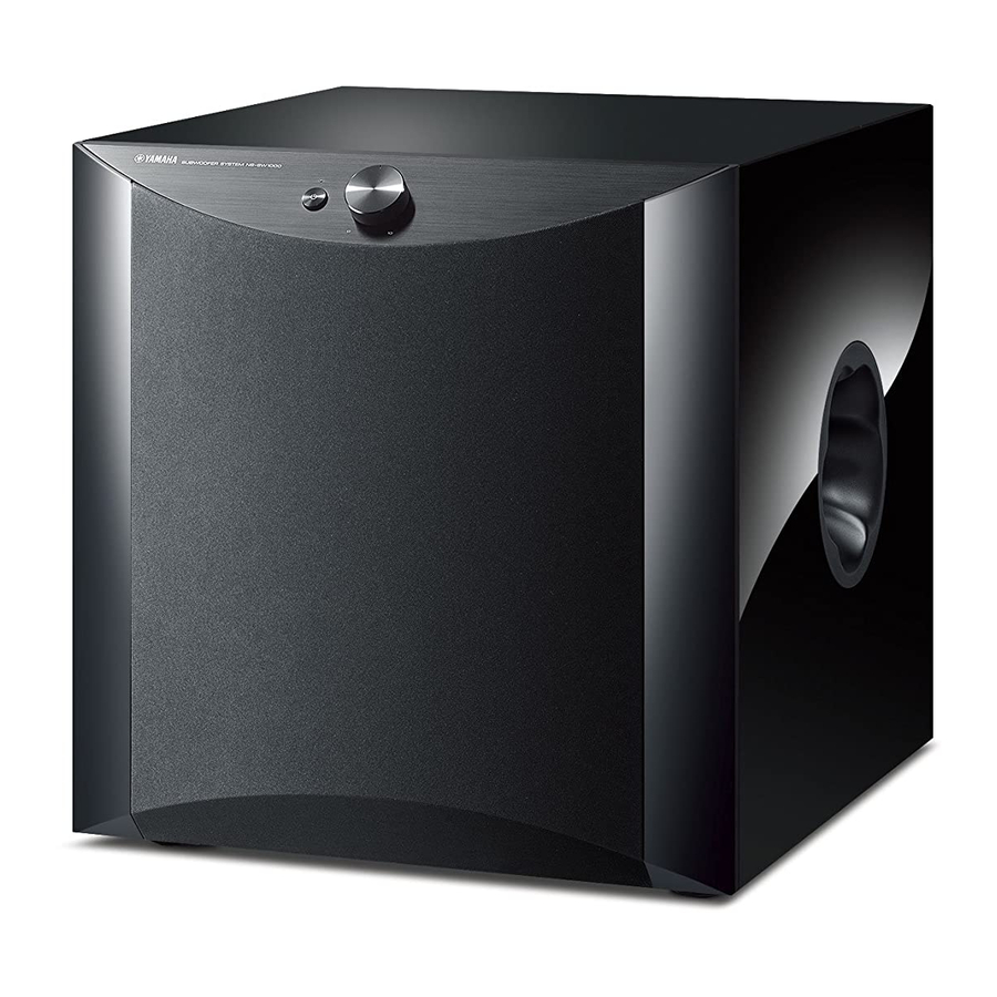
DVX-1000 SYSTEM COMPOSITION / システム構成 The DVX-1000 consists of the DVR-1000, NX-XSW1000 and NX-P1000. DVX-1000 は、DVR-1000、NX-SW1000 および NX-P1000 で構成されています。 DVX-1000 DVR-1000 x1 NX-SW1000 x1 NX-P1000 x2 STANDBY/ON EJECT DIMMER SLEEP BASS TREBLE NIGHT FREQ/TEXT REPEAT PROG PTY SEEK MODE START SHUFFLE PRESET PRESET... - Page 6 DVX-1000 NX-SW1000 Front view Side view NX-P1000 Front view Side view...
-
Page 7: Rear Panels
DVX-1000 REAR PANELS DVR-1000 R, K, A, L models Rear view Bottom view G model Rear view Bottom view... - Page 8 DVX-1000 F model DVR-1000 Rear view Bottom view J model Rear view Bottom view...
- Page 9 DVX-1000 NX-SW1000 K model R model A model G, F models...
- Page 10 DVX-1000 NX-SW1000 L model J model NX-P1000 Rear view Bottom view Red (+) Black (-)
-
Page 11: Remote Control Panel
ENTER ENTER TOP MENU TOP MENU SET UP /RETURN SET UP /RETURN AREA AREA DIRECT DIRECT MODE MODE ENHANCER ENHANCER SURROUND DVD/CD MUTE SURROUND DVD/CD MUTE TUNER TUNER SUBTITLE ANGLE ZOOM AUDIO SUBTITLE ANGLE ZOOM AUDIO DVX-1000 WM23860 DVX-1000 WM23870... -
Page 12: Specifications / 参考仕様
DVX-1000 SPECIFICATIONS / 参考仕様 DVR-1000 TUNER SECTION / チューナー部 GENERAL / 総合 FM Tuning Range / FM 受信周波数範囲 Power Supply Rating / 電源電圧 R, K, A, G, F, L models 87.50 to 108.00 MHz R model 220-240 V, 50/60 Hz J model 76.0 to 90.0 MHz... - Page 13 G and F models 230 V, 50 Hz J model 100V, 50/60Hz Power Consumption / 消費電力 200 W System / 型式 Advanced Yamaha Active Servo Technology アドバンスドヤマハアクティブ サーボテクノロジー Impedance / インピーダンス 6 ohms Speaker Driver / スピーカーユニット 16cm cone woofer, magnetic shielding type 16cm ...
- Page 14 DVR-1000 (1-1/2") 435 (17-1/8") 208 (8-3/16") NX-SW1000 230 (9-1/16") 440 (17-5/16") NX-P1000 This subwoofer system (NX-SW1000) employes Advanced Yamaha Active Servo Technology which Yamaha has developed for reproducing higher quality super-bass sound. 145 (5-11/16") 178 (7") Unit : mm (inch)
-
Page 15: Internal View
DVX-1000 INTERNAL VIEW DVR-1000 Top view q FRONT (1) P.C.B. w FRONT (4) P.C.B. e FRONT (2) P.C.B. r FRONT (5) P.C.B. t AM/FM TUNER y USB P.C.B. u MONO P.C.B. i AV P.C.B. o POWER SUPPLY UNIT !0 HDMI P.C.B. -
Page 16: Disassembly Procedures / 分解手順
DVX-1000 DISASSEMBLY PROCEDURES / 分解手順 (Remove parts in the order as numbered.) (番号順に部品を取り外してください。 ) DVR-1000 1. Removal of Top Cabinet 1. トップキャビネットの外し方 a. q のネジ 6 本、w のネジ 2 本を外します。 (Fig. 1) a. Remove 6 screws (q) and 2 screws (w). (Fig. 1) b. - Page 17 DVX-1000 Locked ロック Flexible flat cable カード電線 1101 Unlocked ロック解除 13 mm (1/2") Flexible flat cable カード電線 Terminal side 端子面 1110 Clip 1105 1102 1104 クリップ 1101 Support MPEG サポートMPEG Use a clip or other item to ground the unit. 1101 USB P.C.B. クリップ等でアースしてください。 1304 1100 1301 1301 MONO P.C.B. 1301, 1302, 1304 Locked 1103 ロック ...
- Page 18 DVX-1000 NX-SW1000 Disassembly Procedure of Front section フロント部の分解手順 1. F パネルサブ ASSY の外し方 1. Removal of Front Panel Sub Ass'y * The front panel sub ass'y is fixed to the cabinet ass'y * F パネルサブ ASSY はキャビネット ASSY にダボで固定され ています。...
- Page 19 DVX-1000 Disassembly Procedure of Rear section リア部の分解手順 1. リアパネル ASSY の外し方 1. Removal of Rear Panel Ass'y a. Remove 8 screws (q). (Fig. 7) a. q のネジ 8 本を外します。 (Fig. 7) b. Remove the rear cover. (Fig. 7) b. リアカバーを取り外します。 (Fig. 7) c. Remove 6 screws (w). (Fig. 7) c. w のネジ...
- Page 20 DVX-1000 NX-P1000 1. Removal of Cover Bottom Ass'y 1. カバーボトム ASSY の外し方 a. 滑り止めパッド 4 個を外します。 (Fig. 9) a. Remove 4 nonskid pads. (Fig. 9) * 一度取り外した滑り止めパッドは使用できません。 必ず、 新 * The old nonskid pad once removed cannot be reused. しい滑り止めパッドに交換してください。 Be sure to replace them with new ones.
-
Page 21: Protection Information Display / プロテクション情報の表示
DVX-1000 NX-SW1000 PROTECTION INFORMATION DISPLAY / プロテクション情報の表示 Connect the DVR-1000 system connector and NX- DVR-1000のシステムコネクターとNX-SW1000のシステム SW1000 system connector by using the system cable コネクターをシステムケーブルで接続し、DVR-1000とNX- and then connect the power cables of DVR-1000 and SW1000の電源コードをACコンセントに接続します。 NX-SW1000 to AC outlets. D V R - 1 0 0 0 の S T A N B Y / O N キ ー ま た は リ モ コ ン の... - Page 22 NX-SW1000 Details of Protection Information プロテクション情報の詳細 1. I protection 1. 過電流プロテクション 原因 : アンプ部に過電流が流れた。 Cause : Excess current flow into amplifier Detection port : P R I ( D S P P . C . B . 7 3 p i n o f 検出ポート...
-
Page 23: Self-Diagnosis Function /
DVX-1000 NX-SW1000 SELF-DIAGNOSTIC FUNCTION / 自己診断機能(ダイアグ) * プロテクションが動作しているときにダイアグを起動するこ * It is not possible to activate the self-diagnostic function とはできません。 while the protection function is at work. * ダイアグ(自己診断機能)を操作するときには、DVR-1000、 * To operate the self-diagnostic function, prepare DVR- 1000, NX-SW1000, system cable and remote controller NX-SW1000、システムケーブルおよびリモコンを用意して... - Page 24 NX-SW1000 Displayed / 表示 (*1) No. Main menu Sub-menu D300 D301 D302 D303 10 RESERVED (Not applied to this model / このモデルには適応されません) 11 RESERVED (Not applied to this model / このモデルには適応されません) 12 RESERVED (Not applied to this model / このモデルには適応されません) 13 DSP PROGRAM WRITING 1 READY FOR WRITING 2 (Not ...
- Page 25 Numeric key (1–4) 数字キー (1−4) DIMMER SLEEP BASS TREBLE NIGHT REPEAT PROG SHUFFLE PRESET PRESET MENU key ON SCREEN MENU ENTER TOP MENU SET UP /RETURN AREA DIRECT MODE ENHANCER SURROUND DVD/CD MUTE TUNER SUBTITLE ANGLE ZOOM AUDIO DVX-1000 WM23860...
- Page 26 NX-SW1000 ダイアグメニュー詳細 Details of Self-Diagnostic Function menu 1. DSP THROUGH 1. DSP THROUGH The output level can be selected by using SUB-MENU. サブメニューで出力レベルを選択できます。 The signal is output in digital full bit without including ヘッドマージンを含まず、デジタルフルビットで出力され the head margin. ます。 1-1 MASTER VOLUME -90 dB 1-1 ...
- Page 27 DVX-1000 NX-SW1000 2-3 FRONT L/R MUTE 2-3 FRONT L/R MUTE Input level SPEAKER OUTPUT (1 kHz) SUBWOOFER (AUX IN) FRONT L/R (50Hz) Both ch, -20 dBm - 47.0 dBm - 0.5 dBm 2-4 SUBWOOFER MUTE 2-4 SUBWOOFER MUTE Input level...
- Page 28 NX-SW1000 5. TEST TONE 5. TEST TONE 内蔵のノイズ発生回路から、サブメニューで指定したチャ The built-in noise generator outputs the test noise ンネルへテストトーンを出力します。 through the channels specified by the sub-menu. The noise frequency for subwoofer is 35 to 250 Hz. サブウーハー用のノイズ周波数は35〜250 Hz 、それ以外 Other than that, the center frequency is 800 Hz. は中心周波数800 ...
- Page 29 DVX-1000 NX-SW1000 7. DEVICE CHECK 7. DEVICE CHECK 各ICのデバイス間通信及びレジスタアクセスの正否を自己 Self-diagnostic is performed to determine whether or 診断します。 not communication between devices of each IC and register access are correct. 7-1 DEVICE CHECK 7-1 DEVICE CHECK Displayed / 表示 Description / 状態...
- Page 30 NX-SW1000 8-3 SERIAL VERSION BIT 4-7 8-3 SERIAL VERSION BIT 4-7 ファームウェアバージョン2桁目を表示します。 The 2nd digit of the firmware version is indicated. 8-4 SERIAL VERSION BIT 0-3 8-4 SERIAL VERSION BIT 0-3 The 3rd digit of the firmware version is indicated. ファームウェアバージョン3桁目を表示します。...
-
Page 31: Amp Adjustment
DVX-1000 NX-SW1000 AMP ADJUSTMENT / アンプ調整 アイドリング電流の確認 CONFIRMATION OF IDLING CURRENT • Right after power is turned on, confirm that the ・ 電源投入直後、R79 (FRONT L ch)、R80 (FRONT R voltage across the terminals of R79 (FRONT L ch), ch)、R71 (SUBWOOFER ch)の端子間電圧を測定し、... -
Page 32: Ic Data
NX-SW1000 IC DATA Digital Signal Processors IC1: D60YA003BPYP225 (DSP (1) P.C.B.) EMIF32 L2 Cache/ L1P Cache Decoder Memory Direct Mapped 4 Banks McASP1 4K Bytes Total 64K Bytes * No replacement part available. Total McASP0 サービス部品供給なし (4-Way) C67x McBSP1 Control Instruction Fetch Registers McBSP0... - Page 33 DVX-1000 NX-SW1000 Port Name Function State1 State2 Signal Name Explanation Resistance SDA0 I/O/Z P33V Outside pull up 10 kΩ CVDD POWER P12V 1.2V power supply DVDD POWER P33V 3.3V power supply DGND Ground CVDD POWER P12V 1.2V power supply DVDD...
- Page 34 NX-SW1000 Port Name Function State1 State2 Signal Name Explanation Resistance CE0N CE0N Inside pull up (external memory enable 3) 13 kΩ CE1N CE1N Inside pull up (external memory enable 3) 13 kΩ CVDD POWER P12V 1.2V power supply CVDD POWER P12V 1.2V power supply DGND...
- Page 35 DVX-1000 NX-SW1000 Pin Name Function State1 State2 Signal Name Explanation Resistance DVDD POWER P33V 3.3V power supply DGND Ground HD7/GP0[3] DSP_INT3 DSP interrupt signal output 13 kΩ HD9/GP0[9] General purpose I/O port (no used) 13 kΩ HD10/GP0[10] General purpose I/O port (no used) 13 kΩ...
- Page 36 NX-SW1000 IC4: LC89057W-VF4AD-E (DSP (1) P.C.B.) Digital Audio Interface Transceiver SDIN SLRCK SBCK RDATA XMODE RLRCK DGND DVDD DVDD DGND TMCK/PIO0 RBCK TBCK/PIO1 RMCK TLRCK/PIO2 AGND TDATA/PIO3 AVDD TXO/PIOE *: Pull-down resistor internal RXOUT Microcontroller Cbit, Ubit RERR Input Selector Demodulation Data RDATA...
- Page 37 DVX-1000 NX-SW1000 Pin No. Function Name Detail of Function RXOUT Output pin of input bi-phase selection data Input pin of TTL-compatible digital data Digital data input pin with built-in amplifier that supports coaxial Input pin of TTL-compatible digital data Input pin of TTL-compatible digital data...
- Page 38 NX-SW1000 IC13: M30626FHPFP (DSP (1) P.C.B.) Microprocessor Port P0 Port P1 Port P2 Port P3 Port P4 Port P5 Port P6 <VCC2 ports> <VCC1 ports> Internal peripheral functions A/D converter System clock generation circuit (10-bit 8-channel Timer (16-bit) Expandable up to 26-channel) XIN-XOUT Output (timer A): 5 UART or...
- Page 39 DVX-1000 NX-SW1000 Pin No. Pin Name Function Name I/O Type Description P9_6/ANEX1/SOUT4 SOUT4 Send Data to E-Vol P9_5/ANEX0/CLK4 CLK4 Serial Clock for E-VOl Communication P9_4/DA1/TB4IN pull down P9_3/DA0/TB3IN Limiter Level Control P9_2/TB2IN/SOUT3 SOUT3 Send Data to D60Y P9_1/TB1IN/SIN3 SIN3 Receive Data from D60Y...
- Page 40 NX-SW1000 Pin No. Pin Name Function Name I/O Type Description P4_3/A19 P4_3 CODEC Soft Mute P4_2/A18 P4_2 Power Relay Control P4_1/A17 P4_1 Interruput for I2C communication request P4_0/A16 pull down P3_7/A15 pull down P3_6/A14 pull down P3_5/A13 pull down P3_4/A12 pull down P3_3/A11 pull down...
-
Page 41: Block Diagrams
DVX-1000 BLOCK DIAGRAMS DVR-1000 BLOCK DIAGRAM FRONT (1) FRONT (2), (4), (5) • See page 63 → SCHEMATIC DIAGRAM • See page 64 → SCHEMATIC DIAGRAM LOARDER ASS'Y 1 GND LEDS 1 +5VSTBY 3P EH to 2 LD_DVD FRONT (1) - Page 42 DVX-1000 DVR-1000 WIRING DIAGRAM Cable Ass'y 8016 AV P.C.B. HDMI P.C.B. 1301 1114 Loader Ass'y Loader Ass'y Loader Ass'y (Loader Module) (Traverse Module) (Traverse Module) 8014 Power Supply Unit 1110 1102 1101 8015 MONO P.C.B. (SD6.3) 1000 1402 USB P.C.B.
- Page 43 DVX-1000 NX-SW1000 BLOCK DIAGRAM MAIN (4) • See page 74 → MAIN (1) • See page 71, 72 → SCHEMATIC DIAGRAM SCHEMATIC DIAGRAM • See page 73 → SCHEMATIC DIAGRAM – B JK200 IC14 SP TARMINAL SPEAKER L IC10 DSP F...
-
Page 44: Pin Connection Diagram
DVX-1000 PIN CONNECTION DIAGRAM NX-SW1000 µPC29M33T-E1-AZ KIA7812API KIA7912PI KIA78L05BP LM61CIZ PQ012FZ01ZPH SN74AHC1G08DCKR NJM4580E (TE2) MM74HCU04SJX SN74LV245APWR KIA7805API SN74AHCT080PWR 1: VIN 1: INPUT 2: VC 1:OUTPUT 2: GND 1:OUTPUT 1:OUTPUT 3: VO 2:COMMON 3: GND 2:COMMON 2:INPUT 3: OUTPUT 4: NC... -
Page 45: Printed Circuit Boards
DVX-1000 The first digit of a component indicates the component type. 1xxx : Connector 3xxx : Resistor 5xxx : Coil 7xxx : IC, Transistor, FET PRINTED CIRCUIT BOARDS DVR-1000 2xxx : Capacitor 4xxx : SMD jumper 6xxx : Diode 9xxx : Wire jumper... - Page 46 DVX-1000 The first digit of a component indicates the component type. 1xxx : Connector 3xxx : Resistor 5xxx : Coil 7xxx : IC, Transistor, FET DVR-1000 2xxx : Capacitor 4xxx : SMD jumper 6xxx : Diode 9xxx : Wire jumper...
- Page 47 DVX-1000 The first digit of a component indicates the component type. 1xxx : Connector 3xxx : Resistor 5xxx : Coil 7xxx : IC, Transistor, FET DVR-1000 2xxx : Capacitor 4xxx : SMD jumper 6xxx : Diode 9xxx : Wire jumper...
- Page 48 DVX-1000 The first digit of a component indicates the component type. 1xxx : Connector 3xxx : Resistor 5xxx : Coil 7xxx : IC, Transistor, FET DVR-1000 2xxx : Capacitor 4xxx : SMD jumper 6xxx : Diode 9xxx : Wire jumper...
- Page 49 DVX-1000 The first digit of a component indicates the component type. 1xxx : Connector 3xxx : Resistor 5xxx : Coil 7xxx : IC, Transistor, FET DVR-1000 2xxx : Capacitor 4xxx : SMD jumper 6xxx : Diode 9xxx : Wire jumper...
- Page 50 DVX-1000 The first digit of a component indicates the component type. 1xxx : Connector 3xxx : Resistor 5xxx : Coil 7xxx : IC, Transistor, FET DVR-1000 2xxx : Capacitor 4xxx : SMD jumper 6xxx : Diode 9xxx : Wire jumper...
- Page 51 DVX-1000 The first digit of a component indicates the component type. 1xxx : Connector 3xxx : Resistor 5xxx : Coil 7xxx : IC, Transistor, FET DVR-1000 2xxx : Capacitor 4xxx : SMD jumper 6xxx : Diode 9xxx : Wire jumper...
- Page 52 DVX-1000 The first digit of a component indicates the component type. 1xxx : Connector 3xxx : Resistor 5xxx : Coil 7xxx : IC, Transistor, FET DVR-1000 2xxx : Capacitor 4xxx : SMD jumper 6xxx : Diode 9xxx : Wire jumper...
- Page 53 DVX-1000 The first digit of a component indicates the component type. 1xxx : Connector 3xxx : Resistor 5xxx : Coil 7xxx : IC, Transistor, FET DVR-1000 2xxx : Capacitor 4xxx : SMD jumper 6xxx : Diode 9xxx : Wire jumper...
- Page 54 DVX-1000 NX-SW1000 Point q Pin 29 of IC4 Semiconductor Location DSP (1) (Side A) Ref. No. Location DSP (3) MAIN (1) (CB304) (CB2) LED0 /FMT LED1 LED2 Point w Pin 13 of IC13 /SWMT LED3 SELF_SW IC10 DGND IC11 PLDET...
- Page 55 DVX-1000 Semiconductor Location DSP (1) (Side B) Ref. No. Location...
- Page 56 DVX-1000 NX-SW1000 Semiconductor Location DSP (2) (Side A) DSP (3) (Side A) Ref. No. Location D301 D302 DSP (1) (W3) DSP (1) DSP (1) DSP (1) (W2) (W7) (W8) D303 D304 SYSTEM CONNECTOR DSP (2) (Side B) DSP (3) (Side B)
- Page 57 DVX-1000 NX-SW1000 Semiconductor Location MAIN (1) (Side A) Ref. No. Location Speaker DSP (1) MAIN (2) MAIN (4) MAIN (2) DSP (1) (W9) (W3B) (W1B) (W2B) (W4) MAIN (1) (Side B)
- Page 58 DVX-1000 NX-SW1000 R, K, A, L models Semiconductor Location MAIN (2) (Side A) MAIN (3) (Side A) Ref. No. Location DSP (1) POWER TRANSFORMER DSP (1) G, F, J models (W6) (W5) POWER POWER CABLE TRANSFORMER MAIN (1) AC IN...
-
Page 59: Schematic Diagrams
DVX-1000 The first digit of a component indicates the component type. 1xxx : Connector 3xxx : Resistor 5xxx : Coil 7xxx : IC, Transistor, FET SCHEMATIC DIAGRAMS DVR-1000 2xxx : Capacitor 4xxx : SMD jumper 6xxx : Diode 9xxx : Wire jumper... - Page 60 DVX-1000 The first digit of a component indicates the component type. 1xxx : Connector 3xxx : Resistor 5xxx : Coil 7xxx : IC, Transistor, FET DVR-1000 2xxx : Capacitor 4xxx : SMD jumper 6xxx : Diode 9xxx : Wire jumper...
- Page 61 DVX-1000 The first digit of a component indicates the component type. 1xxx : Connector 3xxx : Resistor 5xxx : Coil 7xxx : IC, Transistor, FET DVR-1000 2xxx : Capacitor 4xxx : SMD jumper 6xxx : Diode 9xxx : Wire jumper...
- Page 62 DVX-1000 The first digit of a component indicates the component type. 1xxx : Connector 3xxx : Resistor 5xxx : Coil 7xxx : IC, Transistor, FET DVR-1000 2xxx : Capacitor 4xxx : SMD jumper 6xxx : Diode 9xxx : Wire jumper...
- Page 63 DVX-1000 The first digit of a component indicates the component type. 1xxx : Connector 3xxx : Resistor 5xxx : Coil 7xxx : IC, Transistor, FET DVR-1000 2xxx : Capacitor 4xxx : SMD jumper 6xxx : Diode 9xxx : Wire jumper...
- Page 64 DVX-1000 The first digit of a component indicates the component type. 1xxx : Connector 3xxx : Resistor 5xxx : Coil 7xxx : IC, Transistor, FET DVR-1000 2xxx : Capacitor 4xxx : SMD jumper 6xxx : Diode 9xxx : Wire jumper...
- Page 65 DVX-1000 The first digit of a component indicates the component type. 1xxx : Connector 3xxx : Resistor 5xxx : Coil 7xxx : IC, Transistor, FET DVR-1000 2xxx : Capacitor 4xxx : SMD jumper 6xxx : Diode 9xxx : Wire jumper...
- Page 66 DVX-1000 The first digit of a component indicates the component type. 1xxx : Connector 3xxx : Resistor 5xxx : Coil 7xxx : IC, Transistor, FET DVR-1000 2xxx : Capacitor 4xxx : SMD jumper 6xxx : Diode 9xxx : Wire jumper...
- Page 67 DVX-1000 The first digit of a component indicates the component type. 1xxx : Connector 3xxx : Resistor 5xxx : Coil 7xxx : IC, Transistor, FET DVR-1000 2xxx : Capacitor 4xxx : SMD jumper 6xxx : Diode 9xxx : Wire jumper...
- Page 68 DVX-1000 The first digit of a component indicates the component type. 1xxx : Connector 3xxx : Resistor 5xxx : Coil 7xxx : IC, Transistor, FET DVR-1000 2xxx : Capacitor 4xxx : SMD jumper 6xxx : Diode 9xxx : Wire jumper...
- Page 69 DVX-1000 The first digit of a component indicates the component type. 1xxx : Connector 3xxx : Resistor 5xxx : Coil 7xxx : IC, Transistor, FET DVR-1000 2xxx : Capacitor 4xxx : SMD jumper 6xxx : Diode 9xxx : Wire jumper...
- Page 70 DVX-1000 DVR-1000 POWER SUPPLY UNIT Page 63 A1 Page 61 E1 to FRONT (1)_1105 to AV_1111 * Components having special characteristics are marked Z and must be replaced * Z印のある部品は、安全性確保部品を示しています。部品の交換が必要な場合、パーツリストに記載さ with parts having specifications equal to those originally installed. れている部品を使用してください。...
- Page 71 DVX-1000 NX-SW1000 SCHEMATIC DIAGRAMS DSP 1/2 IC13: M30626FHPFP Single-chip 16-bit CMOS microprocessor BUFFER DSP (1) 1/2 Port P0 Port P1 Port P2 Port P3 Port P4 Port P5 Port P6 <VCC2 ports> <VCC1 ports> BUFFER Internal peripheral functions A/D converter...
- Page 72 DVX-1000 NX-SW1000 DSP 2/2 IC17: YAC523-VZ Digital volume DSP (1) 2/2 REGULATOR 0~95dB OUT1 – REF1B 0~+31.5dB REF1A VolA: 30kohm 12.0 0~95dB OUT2 – REF2B 0~+31.5dB REF2A VolA: 30kohm 0~95dB OUT3 – REF3B 0~+31.5dB REF3A VolA: 30kohm 0~95dB OUT4 –...
- Page 73 DVX-1000 NX-SW1000 MAIN 1/2 Page 74 to MAIN (4)_W1B POWER AMP 47.5 PROTECTION MUTE Page 71 to DSP (1)_W4 Page 74 to MAIN (2)_W2B FRONT L Page 72 to DSP (1)_W9 STK433-330-E Page 74 STK433-330Y-E to MAIN (2)_W3B RELAY DRIVE 47.5...
- Page 74 DVX-1000 NX-SW1000 MAIN 2/2 POWER DOWN DETECT FRONT L AC DETECT IC14 Page 73 SPEAKERS 13.0 to MAIN (1)_W1A IC12 10.2 Page 71 to DSP (1)_W5 REGULATOR IC10 1P 0.22 19.2 G, F 12.0 AC15.2 Page 71 to DSP (1)_W6 to POWER TRANSFORMER 11.6...
-
Page 75: Replacement Parts List
DVX-1000 REPLACEMENT PARTS LIST ELECTRICAL COMPONENT PARTS WARNING Components having special characteristics are marked Z and must be replaced with parts having specifications equal to those originally installed. The chip resistor is not supplied as a replacement part. * When a chip resistor is necessary, use the following part. - Page 76 DVX-1000 NX-SW1000 P.C.B. DSP Ref No. Part No. Description Remarks Markets 部品名 ランク WM892700 P.C.B. PCB DSP CB200 VQ044400 CN.BS.PIN FFCコネクター 01 CB201 VB858400 CN.BS.PIN ベースピン CB202 VB858500 CN.BS.PIN ベースピン CB203 VB858800 CN.BS.PIN ベースピン CB304 VB858700 CN.BS.PIN ベースピン UR837100 C.EL 10uF 16V ケミコン C2‑12 US135100 C.CE.CHP...
- Page 77 DVX-1000 NX-SW1000 P.C.B. DSP Ref No. Part No. Description Remarks Markets 部品名 ランク C105 UR818100 C.EL 100uF 6.3V ケミコン C106‑111 US135100 C.CE.CHP 0.1uF 16V チップセラコン C112 US035100 C.CE.CHP 0.1uF 16V B チップセラコン C113 UU266220 C.EL 2.2uF 50V ケミコン FW 01 C114 US061330 C.CE.CHP 33pF 50V B チップセラコン C115‑117 UU267100 C.EL 10uF 50V...
- Page 78 DVX-1000 NX-SW1000 P.C.B. DSP & MAIN Ref No. Part No. Description Remarks Markets 部品名 ランク D9‑12 VV220700 DIODE.SHOT RB501V‑40 ショットキーダイオード 01 VU990100 DIODE.ZENR MA8027 2.7V ツェナーダイオード 01 VT332900 DIODE 1SS355 ダイオード 01 D15‑16 VU993800 DIODE.ZENR MA8068‑M 6.8V ツェナーダイオード 01 VU993000 DIODE.ZENR MA8056‑M 5.6V ツェナーダイオード 01 VU992600 DIODE.ZENR...
- Page 79 DVX-1000 NX-SW1000 P.C.B. MAIN Ref No. Part No. Description Remarks Markets 部品名 ランク CB16 VP245600 ベース付ポスト C1‑3 UR867100 C.EL 10uF 50V ケミコン 01 C4‑5 WJ602900 C.MYLAR 100pF 50V K マイラーコン 01 WJ605000 C.MYLAR 0.01uF 50V J マイラーコン 01 C7‑8 US061220 C.CE.CHP 22pF 50V B チップセラコン UR867100 C.EL 10uF 50V ケミコン 01 C10‑11...
- Page 80 DVX-1000 NX-SW1000 P.C.B. MAIN Ref No. Part No. Description Remarks Markets 部品名 ランク UR866100 C.EL 1uF 50V ケミコン C78‑79 WJ605000 C.MYLAR 0.01uF 50V J マイラーコン 01 C80‑81 WE514200 C.EL 6800uF 63V ケミコン C83‑84 UR749220 C.EL 2200uF 25V ケミコン 03 UR73A100 C.EL 10000uF 16V ケミコン 03 C88‑89 VR168300 C.MYLAR 0.1uF 50V...
- Page 81 DVX-1000 NX-SW1000 P.C.B. MAIN Carbon Resistors Ref No. Part No. Description Remarks Markets 部品名 ランク Value 1/4W Type Part No. 1/6W Type Part No. Value 1/4W Type Part No. 1/6W Type Part No. 1.0 Ω 3100 3100 10 kΩ 7100 7100 HJ35...
- Page 82 DVX-1000 DVR-1000 OVERALL ASS’Y 8005 8017 1003 8008 8010 8009 1008 8011 8007 1007 1002 8015 8016 8002 1009 1004 8014 8002 1001 8022 1006 8013 1001 1001 8012 1001 1001...
- Page 83 DVX-1000 ACCESSORIES For DVR-1000 Ref No. Part No. Description Remarks Markets 部品名 ランク * 101 AAX89440 TOP CABINET 3139 244 17561 トップキャビネット 2000 2002 2003 * 119 AAX89540 BUTTON VOLUME DVR1000 3139 244 17572 ボタンVOLUME 2004 2007 * 120 AAX89510 BUTTON INPUT/STOP 3139 244 17852 ボタンINPUT/STOP * 121 AAX89520 BUTTON PLAY/PAUSE 3139 244 17862 ボタンPLAY/PAUSE ...
- Page 84 DVX-1000 NX-SW1000 OVERALL ASS’Y Ref No. Part No. Description Remarks Markets 部品名 ランク * 1‑1 WM907300 FRONT PANEL SUB ASS'Y with PANEL/GRILLE FパネルサブASSY 1‑2 WC904800 EMBLEM エンブレム 2-1 (2) * 2‑1 WM892200 P.C.B. ASS'Y MAIN PCB MAIN * 2‑1 WM892400 P.C.B. ASS'Y MAIN RKAL PCB MAIN 2-32 2-34 * 2‑1 WM892500 P.C.B. ASS'Y...
- Page 85 DVX-1000 NX-P1000 OVERALL ASS’Y Ref No. Part No. Description Remarks Markets 部品名 ランク X9488A00 DRIVER WOOFER 12cm 6Ω with CABLE 467388 スピーカーユニット X9489A00 DRIVER TWEETER 2.5cm 6Ω 467389 スピーカーユニット AAX89070 NETWORK ASS'Y 469358 ネットワークASSY * 3‑3 AAX89150 CEMENT RESISTOR R1 3Ω 5W 473855 セメント抵抗 * 3‑4 AAX89030 ELECTROLYTIC CAPASITOR C2 3.9uF 63V 468738 ケミコン * 3‑5 AAX88970 ELECTROLYTIC CAPASITOR...
-
Page 86: Remote Control
DVD/CD MUTE 78-BC 78-BC 78-BC 78-BC SUBTITLE 7C-AA – – – TUNER TUNER SUBTITLE ANGLE ZOOM AUDIO SUBTITLE ANGLE ZOOM AUDIO ANGLE – – 7C-AE – ZOOM 7C-D7 – – – AUDIO 7C-AD – 78-A5 – DVX-1000 WM23860 DVX-1000 WM23870...