Table of Contents
Advertisement
TABLE OF CONTENTS
1 Safety Precautions----------------------------------------------- 2
2 Specifications ----------------------------------------------------- 3
3 Technical Explanation ------------------------------------------ 5
4 Location of Controls and Components ------------------- 7
5 Installation Instructions ---------------------------------------- 9
6 Operating Instructions-----------------------------------------23
7 Test Mode ----------------------------------------------------------26
8 Service Mode -----------------------------------------------------35
9 Troubleshooting Guide ----------------------------------------37
10 Disassembly and Assembly Instructions ---------------40
11 Maintenance-------------------------------------------------------59
12 Factory Setting ---------------------------------------------------60
13 Schematic Diagram ---------------------------------------------64
14 Exploded View and Replacement Parts List -----------68
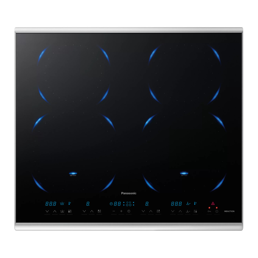
Induction Heating Hob (Built-in)
Model No.
Model No.
Model No.
Model No.
Color:
Destination
PAGE
© Panasonic Corporation 2012 Unauthorized copy-
ing and distribution is a violation of law.
KY-B84BXBXD
KY-B64BXBXD
KY-B84BGBXD
KY-B64BGBXD
Black
UK, Germany, Italy, France, Spain,
Belgium, the Netherlands, Denmark,
Sweden, Switzerland, Austria, Norway
IHB1211002CE
Advertisement
Table of Contents

Related Manuals for Panasonic KY-B84BXBXD


Summary of Contents for Panasonic KY-B84BXBXD
-
Page 1: Table Of Contents
9 Troubleshooting Guide ----------------------------------------37 10 Disassembly and Assembly Instructions ---------------40 11 Maintenance-------------------------------------------------------59 12 Factory Setting ---------------------------------------------------60 13 Schematic Diagram ---------------------------------------------64 14 Exploded View and Replacement Parts List -----------68 © Panasonic Corporation 2012 Unauthorized copy- ing and distribution is a violation of law. -
Page 2: Safety Precautions
1 Safety Precautions... -
Page 3: Specifications
2 Specifications KY-84BX BXD, KY-84BG BXD Model KY-B84BX BXD KY-B84BG BXD Installation type Built-in Power supply Single-phase connection (220-240V ~ 50Hz)/ Three-phase connection (380-415V 2N ~ 50Hz) Power consumption 7200W Standby power consumption 0.2W When the power switch is turned off Dimensions Full product size 773mm(W) x 536mm(D) x 66mm(H) - Page 4 KY-64BX BXD, KY-64BG BXD Model KY-B64BX BXD KY-B64BG BXD Installation type Built-in Power supply Single-phase connection (220-240V ~ 50Hz)/ Three-phase connection (380-415V 2N ~ 50Hz) Power consumption 7200W Standby power consumption 0.2W When the power switch is turned off Dimensions Full product size 607mm(W) x 536mm(D) x 66mm(H) (approx.)
-
Page 5: Technical Explanation
3 Technical Explanation 3.1. Power Control Power set Left front IH 1000 1300 1500 1800 2600 3300 Left rear IH 1000 1200 1500 1800 Right front IH 1000 1300 1500 1800 2600 3300 Right rear IH 1000 1200 1500 1800 •... - Page 6 3.3. Location of Controls and Components 3.3.1. Functional Assignments of Boards...
-
Page 7: Location Of Controls And Components
4 Location of Controls and Components... -
Page 9: Installation Instructions
5 Installation Instructions... -
Page 23: Operating Instructions
6 Operating Instructions Operational checks and procedures Operation Description Preparation: Fill suitable pots with water and place them on the left/right IH heaters. (Refer to: Types of Pots and Pans that can be used in the Operating Instruc- tions.) 1. Turn the main power switch on. 1) The Power switch is lit. - Page 24 Operation Description Preparation: Place an empty frying pan on the heater. 3. Pan frying temperature control • "200" is displayed and the preheating lamp starts blinking. sensor (1)Press the Grilling temperature • Set the temperature with Up and Down buttons. adjustment button.
- Page 25 Operation Description 5. Timer • The heat level indicator is displayed on level 7. (1)Press the "Off/On" button. (The cooling fan starts spinning.) (2)Touch the Timer button and select the IH heater. (3)Press the "+"button or press the "-" button. * Press and hold for rapid mode.
-
Page 26: Test Mode
7 Test Mode 7.1. Power supply check mode (OVD checking) In this mode, an abnormal power supply can be checked. Use this mode, when one or more of the following symptom occur. (The test mode works only on the front heaters.) Symptom: •... - Page 27 Operation Indicators on the operation panel 6.Place a pot filled with water on either the left front IH heater or the right ⑥ front IH heater. Example: Right IH heater 7.Press the (Off/On) button. 8.The status is displayed on the display window of the heater that does ⑧...
- Page 28 7.2. Memory of total hours used and the latest error code recall mode In this mode, you can check the total hours of use from the factory shipment and three (3) recent errors. Operating procedures Operation Indicators on the operation panel How to operate (Each button operation has a buzzer sound.) Displaying to the hours used 1.Turn the main power switch on.
- Page 29 Operation Indicators on the operation panel Displaying the latest error code 8.Press the Timer (-) button to select a heater. ⑧ ⑨ Shows the latest error code. 9.Shows the latest error code. Example: H53 10.Press the Timer button to display the previous error code issued. ⑩...
- Page 30 7.3. Integral power consumption display mode In this mode, a rough estimate of integral power consumption is shown. Operating procedures Operation Indicators on the operation panel How to operate (Each button operation has a buzzer sound.) 1.Turn the main power switch on. ①...
- Page 31 7.4. Demonstration mode In this mode, the button operations are available, but heating does not occur. Operating procedures Operation Indicators on the operation panel How to operate(Each button operation has a buzzer sound.) 1. Turn the main power switch on. ①...
- Page 32 7.5. Cooling fan operation mode Operating procedures Operation Indicators on the operation panel How to operate(Each button operation has a buzzer sound.) 1. Turn the main power switch on. ① ② 2.Within three (3) seconds, simultaneously press the Up button of the left rear IH heater and the Timer (+) buttons.
- Page 33 7.6. IH heater power display mode Operating procedures Operation Indicators on the operation panel How to operate(Each button operation has a buzzer sound.) 1. Turn the main power switch on. ① ② 2.Within three (3) seconds, simultaneously press the left rear heating Down and the Timer (-) buttons.
- Page 34 7.7. Deep-frying temperature adjustment mode In this mode, if the actual oil temperature differs from the displayed temperature, the temperature is tried to be adjusted based on the pot. Before executing the adjustment, measure the temperature at the center of the oil, and check the difference from the displayed tem- perature.
-
Page 35: Service Mode
8 Service Mode 8.1. Self-diagnosis functions and remedy/repair methods 8.1.1. U indications "U##" When the safety function is activated, a buzzer will sound and the error indication "U##" will appear. Note the U number and remove the U display by pressing the Off/On button. Follow the remedy provided for U factors. If the U fac- tor still appears after trying the remedy, there is a breakdown and repairs must be carried out as itemized in the B factor procedures, shown below. - Page 36 Error codes Symptom/state Cause Factor Checkpoint Remedy/Repair Description "U13" appears while heat- The overheating safety Is the pan/pot empty? Turn the power off. Empty pot auto-shutoff ing a pan/pot, and the function triggers when the Have the contents of the Make sure that there is food (for the front IH power turns off.
-
Page 37: Troubleshooting Guide
9 Troubleshooting Guide 9.1. H indications "H##" Error Codes Symptom/State Checkpoint Remedy/Repair Description "H01" appears when the main Have those connectors been surely Ensure the connection. Open circuit detection for the IH power switch is turned on. inserted? coil-center thermistor. (Front IH heater) *E.g. - Page 38 Error Codes Symptom/State Checkpoint Remedy/Repair Description "H21" appears when main Check the wire connections of the Ensure the connection. Breakdown detection for the power power switch is turned on. P.C.board A and P.C.board B. relay. *E.g. CN2 on P.C.board A. CN503 on P.C.board B.
- Page 39 9.2. Other faults 1. The unit is not turned on when the power switch is pressed. Checkpoint Probable Cause Remedy/Repair P.C.board A(Right) The unit is not turned on when the Check the wire connections of right Ensure that the connection is P.C.board B(Right) power switch is pressed.
-
Page 40: Disassembly And Assembly Instructions
10 Disassembly and Assembly Instructions Important • Be sure to turn off the circuit breaker before disassembling the IH cooktop. • For assembly, refer to the tips provided and bear in mind that assembly is done in the reverse order of the disassembly proce- dure. - Page 41 10.1. Main IH Cooktop Unit 1. Remove the main IH cooktop unit from the cabinet (Built- in type). • If the top plate has been bonded to the counter with seal- ant tape (Sealing tape A), remove the tape with a plastic spatula, taking care not to damage the counter.
- Page 42 10.3. Spacer A 1. Remove the Spacer A.
- Page 43 10.4. IH coil 10.4.1. Front IH coils (Left/Right) 1. Lift the front IH coil from the right side, and remove the connector (CN4). The specified screws are indicated with an arrow. 2. Remove screw K (2 pcs) of the front IH coil lead wire that connects to P.C.board A (Lin A)(Lout A).
- Page 44 3. Remove the front IH coil. Note: For the models with Luminous circles, before removing Thermistor A of the front IH coil, remove Screw G from 4 Luminous circle LEDs and detach the connector. Screw G: Pan Head P-tite Screw 4+8...
- Page 45 10.4.2. Rear IH coils (Left/Right) 1. Remove screw K (2 pcs) of the rear IH coil lead wire that connects to P.C.board A (Lin B)(Lout B). Screw K: Terminal screw 4+8 The specified screws are indicated with an arrow. 2. Open cable clip E that holds the thermistor lead wire.
- Page 46 3. Unplug the thermistor lead wire connector (CN9). 4. Remove the rear IH coil.
- Page 47 Note: For models with Luminous circles, before removing the Thermistor B/D of the rear IH coil, remove Screw G from 4 Liminous circle LEDs and detach the connector. Screw G: Pan Head P-tite screw 4+8 Left rear IH coil assembly...
- Page 48 Right rear IH coil assembly Note: When setting the IH coil, be sure to set the holes of the IH coil to the guides, and check that the IH coil moves up and down. 10.4.3. Operation Unit 1. Unplug Control lead wire C connector (CN6). 2.
- Page 49 10.4.4. L1 springs 1. Remove the L1 springs (13 pcs). (KY-B84BX/B84BG) (KY-B64BX/B64BG)
- Page 50 10.4.5. Heat sink ducts (Left/Right) (KY-B84BX/B84BG) 1. Remove the Heat sink duct fixing screw A (1 pcs) and screw E (3 pcs) and screw L (1 pcs). Screw A: Panhead Deltite screw 4+6 Screw E: Panhead P-tite screw 4+12 Screw L: Panhead Deltite screw 4+16(Black) 2.
- Page 51 (KY-B64BX/B64BG) 1. Remove the Heat sink duct fixing screw A (1 pcs) and screw E (3 pcs) and screw N (1 pcs). Screw A: Panhead Deltite screw 4+6 Screw E: Panhead P-tite screw 4+12 Screw N: Panhead Deltite screw 4+20 (Black) 2.
- Page 52 10.4.6. Fan motors (Left/Right) The left and right fan motors have the same set of components. The disassembly procedure for both fans is identical. 1. Disconnect connector CN509. 2. Remove Fan motor fixing screw C (2 pcs). Screw C: Panhead Deltite screw 4+25 3.
- Page 53 10.4.7. P.C.board B (Left) 1. Unplug the connectors (Black: CN501) and (White: CN510) that connect Control lead wire A to P.C.board B. The specified screws are indicated with an arrow. 2. Remove screw K (2 pcs) that affixes connectors (CN505) and (CN506) to the power cord.
- Page 54 P.C.board B (Left) assembly When setting P.C.board B (Left), secure the Ground line by setting it through the two points of the P.C.board base. 10.4.8. P.C.board B (Right) 1. Unplug the connectors (Black: CN501) and (White: CN510) of Control lead wire B that lead to P.C.board B (right).
- Page 55 5. Remove P.C.board B (right) holding screw G (3 pcs). Screw G: Pan Head P-tite Screw 4+8 6. Remove the P.C.board B (Right). P.C.board B (Right) assembly When setting P.C.board B (right), wire the Ground line by setting it through the two ribs of the P.C.board base. 1.
- Page 56 10.4.9. P.C.board A (Left/Right) 1. Unplug connector (White: CN11) from Control lead wire A/B that leads to P.C.board A. 2. Remove P.C.board A holding screw G (3 pcs) and Heat sink holding screw J (1 pcs). Screw G: Pan Head P-tite Screw 4+8 Screw J: Pan Head P-tite Screw 4+16 3.
- Page 57 10.4.11. P.C.board base 1. Remove screw B (5 pcs) from the P.C.board base. Screw B: Pan Head Deltite Screw 4+10 2. Remove the P.C.board base. 10.5. Checking after assembly Checking ground line 1. Check to confirm that there is an electrical connection between the ground line of power cord and the side plates. The electric connection between those parts must be ensured.
- Page 58 2. Touch the Top plate frame with an Insulation resistance tester to confirm that resistance can be maintained at higher than 1 M for 1 minute. (Ignore the momentary swing of the tester's needle immediately after touching.) (Parts to measure: Two contrasts of the Power line and chassis)
-
Page 59: Maintenance
11 Maintenance... -
Page 60: Factory Setting
12 Factory Setting 12.1. Manufacturing date code, serial number location The serial number is pasted at the center on the front of the unit. - Page 61 12.2. Repacking method (KY-B84BX/B84BG BXD)
- Page 62 (KY-B64BX/B64BG BXD)
- Page 63 12.3. Packing dimension (KY-B84BX/B84BG BXD) (KY-B64BX/B64BG BXD)
-
Page 64: Schematic Diagram
13 Schematic Diagram 13.1. Wiring connection... - Page 65 13.2. Electric circuit (KY-B84BX/B64BX BXD)
- Page 66 (KY-B84BG/B64BG BXD)
- Page 67 13.3. Wiring treatment...
-
Page 68: Exploded View And Replacement Parts List
14 Exploded View and Replacement Parts List 14.1. Exploded View (KY-B84BX BXD / KY-B84BG BXD) - Page 69 14.2. Replacement parts list (KY-B84BX BXD) Safety Ref. Part No. Part Name & Description Quan- Remarks tity AZB03-B72-0S Top plate Ass'y Black. W/No.2. Silicon fluid compounds AZB06CA61-0S Sealing tape B 2 pieces set AZD64-B72-0S Left rear IH coil W/No.5-7. Silicon fluid compounds AZD77-A74-0S Right rear IH coil W/No.5-7.
- Page 70 PACKING SPECIFICATIONS Safety Ref. Part No. Part Name & Description Quan- Remarks tity AZZ05-B72 Cartonbox AZZ10CA61 Cushion UP AZZ15CA61 Cushion R AZZ65CA61 Cushion CF AZZ16CA61 Cushion L AZZ66CA61 Cushion CR AZY02-A74 Operating instructions English/German/French/Dutch AZY04-A74 Operating instructions B Italian/Spanish/Danish/Swedish/Norwegian AZY16-A74 Installation instructions English/German/French/Dutch AZY18-A74...
- Page 71 14.3. Replacement parts list (KY-B84BG BXD) Safety Ref. Part No. Part Name & Description Quan- Remarks tity AZB03-B73-0S Top plate Ass'y Black. W/No.2. Silicon fluid compounds AZB06CA61-0S Sealing tape B 2 pieces set AZD64-B73-0S Left rear IH coil W/No.5-7. Silicon fluid compounds AZD77-A97-0S Right rear IH coil W/No.5-7.
- Page 72 PACKING SPECIFICATIONS Safety Ref. Part No. Part Name & Description Quan- Remarks tity AZZ05-B73 Cartonbox AZZ10CA61 Cushion UP AZZ15CA61 Cushion R AZZ65CA61 Cushion CF AZZ16CA61 Cushion L AZZ66CA61 Cushion CR AZY02-A74 Operating instructions English/German/French/Dutch AZY04-A74 Operating instructions B Italian/Spanish/Danish/Swedish/Norwegian AZY16-A74 Installation instructions English/German/French/Dutch AZY18-A74...
- Page 73 14.4. Exploded View (KY-B64BX BXD / KY-B64BG BXD)
- Page 74 14.5. Replacement parts list (KY-B64BX BXD) Safety Ref. Part No. Part Name & Description Quan- Remarks tity AZB03-A74-0S Top plate Ass'y Black. W/No.2. Silicon fluid compounds AZB06CA61-0S Sealing tape B 2 pieces set AZD64-B72-0S Left rear IH coil W/No.5-7. Silicon fluid compounds AZD77-A74-0S Right rear IH coil W/No.5-7.
- Page 75 14.6. Replacement parts list (KY-B64BG BXD) Safety Ref. Part No. Part Name & Description Quan- Remarks tity AZB03-A97-0S Top plate Ass'y Black. W/No.2. Silicon fluid compounds AZB06CA61-0S Sealing tape B 2 pieces set AZD64-B73-0S Left rear IH coil W/No.5-7. Silicon fluid compounds AZD77-A97-0S Right rear IH coil W/No.5-7.