Table of Contents
Advertisement
Quick Links
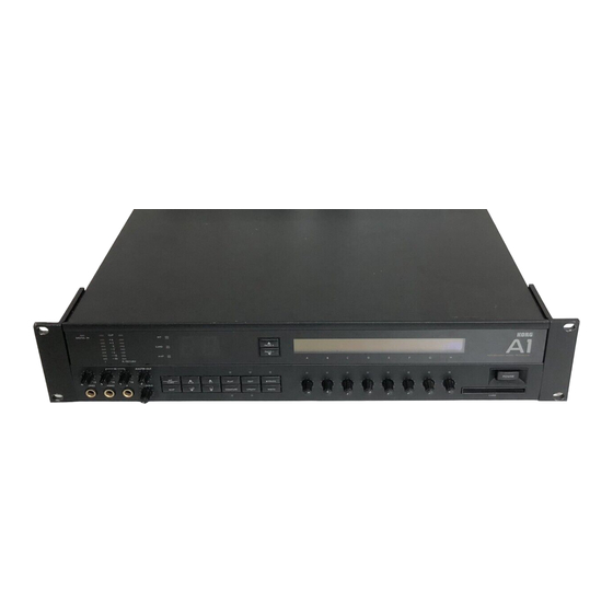
OWNER'S MANUAL
CONTENTS
Identification of Controls and Terminals...4
Basic Operation .............................................................. 6
1. Preparation and Basic Connections...................... 6
2. Play Mode ............................................................. 8
3. Program Editing................................................... 12
The Four Modes and Their Functions............. 15
Play Mode ............................................................. 16
1. Program Selection ............................................... 16
2. Turning Effects ON and OFF ................................. 9
3. Performance Edit ................................................ 20
4. Setting the Master Out Volume. Noise
Reduction Threshold Level and Bypass
Switching in the Play Mode ................................... 21
Edit Mode ....................................................... 22
1. Chain Edit ........................................................... 23
2. Effect Edit ........................................................... 30
3. Program Utility .................................................... 36
Write Mode ............................................................ 40
1. Write Operation .................................................. 40
Global Utility Mode ............................................... 44
1. Setting MIDI Functions......................................... 45
2. Loading Programs From and Saving
to Memory Cards .................................................48
3. Setting Internal Memory Protect Functions ..........50
4. Mapping Programs .............................................. 51
5. Setting Foot Switch Functions ............................. 52
6. Setting the Digital I/O Functions.......................... 53
Connecting the Optional RE1
Remote Editor........................................................ 54
Connecting the Optional
FC6 Foot Controller ................................................. 55
1. Manual 1 (Program Change Mode).......................56
2. Manual 2 (Effect ON/OFF Mode) ......................... 57
3. Connecting Foot Switch 1 and 2 to the SW1
and SW2 Jackson the FCS Rear Pane! ............. 57
A1 Connection Examples ................................. 58
1.Guitar Setup ......................................................... 58
2.Mixers and Multi-track Recorder Setup................. 59
3.Using the Digital I/O.............................................. 59
Troubleshooting..................................................... 60
List of Messages ..................................................... 61
Rack Mount Installation........................................... 62
Specifications and Options ...... ..........................63
Advertisement
Table of Contents

Related Manuals for Korg A1


Summary of Contents for Korg A1
- Page 1 2. Manual 2 (Effect ON/OFF Mode) ......57 3. Connecting Foot Switch 1 and 2 to the SW1 and SW2 Jackson the FCS Rear Pane! ..... 57 A1 Connection Examples ......... 58 1.Guitar Setup ............58 2.Mixers and Multi-track Recorder Setup....59 3.Using the Digital I/O..........
-
Page 2: Table Of Contents
Memory Cards........48 2/ Replacing an Effect ........14 Using the ROM Card Included with 3/ dealing a New Program ......14 Your A1 ..........50 The Four Modes and Their 3. Setting Internal Memory Protect Functions ..........50 Functions ........... 15 4. - Page 3 WARNING THE FCC REGULATION WARNING This equipment generates and uses radio frequency energy and if not installed and used properly, that is, in strict accordance with the manufacturer's instructions, may cause interference to radio and television reception. It has been type tasted and found to comply with, the limits for a class B computing device in accordance with the specifications in Subpart J of Part 15 of FCC Rules, which are designed to provide reasonable protection against such interference in a residential installation.
-
Page 4: Identification Of Controls And Terminals
Use the INT key for selecting programs stored within the lights up when the input level becomes too hot. (The CLIP A1 and the CARD key to select programs stored on ROM indicator does not light up when effect processing levels or RAM cards become excessive.) - Page 5 10. EXT CTRL OUT (external control output) Jack For inserting an external signal processor, guitar Conned to latching type footswitch inputs of external preamp, etc. into the A1 elect signal path. The signal processors or guitar preamps, etc. A1 program SEND (output) and RETURN (input) are only...
-
Page 6: Basic Operation
• Connect stereo sound sources such as a keyboard to the L/MONO and R jack. 2. Connect the mixer or guitar amplifier to the output terminal on the A1’s rear panel. • Conned monaural sound sources such as a guitar amplifier to the L/MONO OUTPUT jack. - Page 7 • The tip of the stereo phone jack is hot, the ring cold and the sleeve ground. 2. Connect the balanced or unbalanced outputs, on the A1'» rear panel, to the effect return input of the mixer.
-
Page 8: Play Mode
+6 dB during Input signal peaks. 5. Select the program number by pressing the UP/DOWN keys. The A1's 100 preset programs are numbered I 00 to I 99. Program 199 ("A1 Example) is selected here as an example. - Page 9 Program I 99 is made up of four effects; Stereo Limiter (SLM1), Playing with Program I 99 Stereo Exciter (SXIT), Stereo Delay (SDLY). and Plate Reverb(PLI). You can play with four effects in program number I99. Each) program can combine up to 7 effects at the same time Any effect can be set to OFF if undesired.
-
Page 10: 2/Useful Functions
2/Useful Functions The MASTER OUT volume control adjusts the overall volume ► Master Volume level of the currently selected program. The level is indicated as a value between 000 and 100 al the OUT indication in the top-right portion of the display. The volume control Is active in all the modes. -
Page 11: Structure Of Effect Programs
An A1 program is an assembly of up to seven effects, which may be Chain simply considered as seven different effect devices linked together. The pattern in which effects are linked is called a Chain. -
Page 12: Program Editing
3 Program Editing The A1 allows you to edit its preset programs to create your own custom programs. 1/Editing Individual Effect Parameters Editing program I99 1. Press the Play Mode key. 2. Select the program to be edited using the UP/DOWN keys. - Page 13 Press the "E" double function edit 5. Press the double function key below the parameter you wish to change. control to show "Right Blend" on The parameter name is displayed in the top right portion of the screen. the display Rotate the "E"...
-
Page 14: 2/ Replacing An Effect
2/ Replacing an Effect The A1 allows you to freely substitute effects in programs with others, as long as the other effects can fit into the respective effect box. 1. Display EDIT SELECT by following steps 1 to 3 on page 12. -
Page 15: The Four Modes And Their Functions
The Four Modes and Their Functions In addition to Play Mode and Edit Mode, the A1 has two additional modes for a total of A: Write Mode for storing programs in memory and Global Utility Mode which provides supplementary functions. -
Page 16: Play Mode
The Play Mode indicator lights up when the At is in Play Mode, at which time you can freely select and play any of 100 preset effect programs or programs provided on A1- compatible memory cards. The Play Mode also contains a Performance Edit Mode that allows real lima editing of selected effect parameters. -
Page 17: 2/ Rearranging The Program Order- Map Play
First, set the desired program (ie., the program to be used first) to map number 00. 3. Select INT or CARD by turning the "D" double function edit control. Storing program Specify “INT” to select internal programs in the A1 or "CARD" to select programs from a numbers as map memory card. - Page 18 The INT Indicator lights up and the A1 returns to the basic Play Mode. However, if you EXIT the Map Mode while on a Map number assigned to a card-stored program, the "CARD" indicator lights up and the A1 will be reading programs from an inserted card in the basic Play Mode.
-
Page 19: Turning Effects On And Off
2 Turning Effects ON and OFF In the Play Mode individual effects in a Chain can easily be turned on and off using the double function edit controls. This function makes h very easy to modify an effects program in real time during a live performance or studio session. 1. -
Page 20: Performance Edit
1. Press the PLAY key to select Play Mode. The Play Mode indicator lights up. 2. Select a program. As an example, select 1 99, "A1 Example." 3. Press the PAGE key. “PERFORMANCE EDIT" is displayed in the top-right of the display. -
Page 21: Setting The Master Out Volume, Noise Reduction Threshold Level And Bypass Switching In The Play Mode
Use the THRESHOLD control to adjust the noise reduction level for the currently selected Threshold level program. The threshold (THR) value is shown in the A1 display. • Switching a program to another causes the master volume and noise reduction threshold levels set in Play Mode to change to the values that were memorized for the new program. -
Page 22: Edit Mode
Edit Mode The Edit Mode enables you to select Chains and Effects, and soil effect parameters, to create your own programs. There are three types of edit functions found in the Edit Mode: Effect Parameter Edit. Chain Edit and Program Utility. -
Page 23: Chain Edit
Chains In the A1, the pattern in which effects are connected is called a Chain, A box in which an effect is contained is called an effect box, and a Chain is a linked pattern off effect boxes, as illustrated below. - Page 24 "hears* your selected frequency. 5. Send/Return Chain A Send/Return Chain allows external devices to be inserted into the A1's effect Chain. The SEND and RETURN jacks on the rear panel function only when a Send/Return Chain is selected.
-
Page 25: Symbols Used To Show Effect Connection In A Chain
Symbols Used to Show Effect Connection in a Chain In the A1 display, the following symbols are used to indicate the connection between effects in a chain. -
Page 26: 1/Replacing Effects In A Chain With Other Effects
1/Replacing effects in a Chain with other effects The following explains the procedure for selecting new effects for each position of a Chain. 1. In the Play Mode, select the program that you wish to edit. (For this example select factory program I 99.) 2. - Page 27 4. Turn the double function edit control (B-H), below the effect to be replaced, Checking the effect size fully counterclockwise. The effect path "----" appears on the display and the effect box size is displayed in the upper right portion off he display. Make sure to check the size of the effect box before replacing the effect.
-
Page 28: 2/ Selecting And Editing A New Chain
2. Selecting and editing a new Chain The Following explains the procedure for selecting and editing an affect Chain. 1. In the Play Mode, select the program that you wish to edit. (For this example select factory program I 99.) 2. -
Page 29: Chain Edit Using The Re-1
Selecting new effects 6. Slowly rotate the double function edit controls (In this example B-D) or press the UP/DOWN keys until the desired effect Is displayed. Available effects are displayed one after another. 7. After the new Chain and effects are selected, press the EDIT button (LED flashing) to return to the EDIT SELECT menu. -
Page 30: Effect Edit
2 Effect Edit The Edit Select menu allows you to select an individual affect and edit it's parameters. 1. In the Play Mode, select the program that you wish to edit. (Once again, select factory program 199 for this example.) 2. -
Page 31: Turning Effects On And Off
Turning Effects ON and OFF Effects can be individually turned ON and OFF in three A1 modes. In the Play Mode and Chain Edit Mode, by pressing the B-H double function edit controls, and in the Parameter Edit Mode, by pressing the "A"... -
Page 32: Using The Dynamic Modulation Function
Using the Dynamic Modulation Function The Dynamic Modulation function allows 'real time" control of effect parameters using MIDI data, volume pedals and input level envelopes. The external controller is called the Dynamic Source and the parameter that it controls is called the Dynamic Parameter. -
Page 33: Setting The Dynamic Amount
Setting the Dynamic Amount The Dynamic Amount setting determines how much control range [he external controller, (Dynamic Source), has over the effect parameter, {Dynamic Parameter). Selecting a positive or negative value for the Dynamic Amount specifies the direction in which the parameter value (Dynamic Para mater) changes. The diagrams below show the range of Dynamic Modulation control at different Dynamic Amount settings (positive and negative). -
Page 34: Copying Effects
"EFFECT COPY" is shown on the display. 3. Rotate the "C" double function edit control to specify the location of program to be copied from: INT for an Internal program of the A1, or CARD for a program stored on memory card. - Page 35 6. After selecting the offset to be copied, press the "F" double function edit control [COPY]. After parameter copying Is 7. "COMPLETED" Is shown on the display. completed. 8. Press the "H" double function edit control [EXIT] to return to the Parameter Edit Mode.
-
Page 36: Program Utility
3 Program Utility The Program Utility Mode provides the 3 following (functions: 1. Setting the master volume and threshold level 2. Setting volume pedal position 3. Setting external control functions Setting the master volume and noise reduction threshold levels (or each program. 1/Setting Levels 1. -
Page 37: 2/Volume Pedal Placement
2/Volume Pedal Placement The output volume can be controlled with a volume pedal connected to the VOL. PEDAL input on the rear panel. Follow the procedure below to set the volume pedal placement or position in an effect Chain. 1. While EDIT SELECT is shown on the display, press the PAGE+ key twice. The Program Utility menu is displayed. -
Page 38: 3/Setting The External Control Functions
3/Setting the External Control Functions The EXT CTRL OUT function allows the A1 to control effect bypass or "channel switching" on external devices using "latching" type switching. For example, connecting the EXT CTRL OUT to the channel switching footswitch jack, on a guitar amp, allows the A1 to control channel switching by program change. -
Page 39: Write Mode
Write Mode The Write Mode is used for saving edited programs to the A1's internal memory or to a RAM card and for copying one program to another. Unless saved in this mode, an edit will be lost when another program is selected. The Write Made also contains the program naming function. -
Page 40: Write Mode
Starting the write operation 1. Press the WRITE Mode key. Specifying a program name You can give the program to be saved a name consisting of up to 12 characters If you don't change the program name, proceed to step 7. 2. - Page 41 Currently selected program Program to be written ID Selecting the program number to 7. Rotate the "D" double function edit control to select INT (Internal A1 program) be written to or CARD. If you are saving to a RAM card, make sure that you slide the write-protect tab at the top left of the card to the OFF position.
-
Page 42: Global Utility Mode
Global Utility Mode The GLOBAL UTILITY MODE contains the following functions: 1. Selling MIDI Functions and parameters 2. Loading programs from and saving lo RAM cards 3. Setting Memory Protect functions 4. Mapping programs 5. Selecting Footswitch 1 and 2 functions 6. -
Page 43: Setting Midi Functions
1 Setting MIDI Functions The "MIDI SETUP 1" page is for the selection of MIDI channels. Page 1 of the MIDI Menu Rotate the "A* double function edit control to select any channel from 1 to 16. Selecting the MIDI transmit- receive channel Setting the OMNI Mode Rotate the "G... - Page 44 Exclusive data program settings lo a MIDI data filer or directly to another A1. Before starting this procedure, connect a MIDI cable from the MIDI OUT of the A1 to the MIDI IN of the receiving device. 1. Press the PAGE + key to go from page [MIDI SETUP 1] to page 2 [MIDI SETUP 2] of the MIDI Menu.
-
Page 45: Receiving A System Exclusive Dump From An External Device
The MIDI exclusive setting should normally be set to DISABLE. Receiving a System Exclusive Dump from an External Device Turn off the memory protect function of tha A1 to allow the reception of data. Setting up 1. Rotate the "E" double function edit control to set the MIDI exclusive setting of the receiving A1 to "ENABLE". -
Page 46: Loading Programs From And Saving To Memory Cards
This Card function allows the LOADING (in bulk) of data from ROW or RAW cards into the A1 internal memory or SAVING the A1 internal memory to RAM cards. This data consists of 100 programs and the Map Play program settings. - Page 47 Saving (writing) A1 programs Make sure beforehand that the write-protect switch on the RAM card is set to OFF. to a RAM card 1. Insert the RAM card into the CARD slot. “RAM CARD INSERTED” or “UNFORMATTED” will appear on the display.
-
Page 48: Using The Rom Card Included With Your A1
Using the ROM Card included with Your A1 The ROM card that comes with your A1 has bean factory installed with the same data contained in the A1's internal programs [100 to 199). If any of the internal programs are... -
Page 49: Mapping Programs
This allows you to call back each program in the order they were entered. MAP Initialization The A1 was shipped with internal programs I 00 to I 99 set to Map numbers 00 to 99. When the Initialization procedure is done the Map is reset to this configuration. -
Page 50: Setting Foot Switch Functions
5 Setting Foot Switch Functions Foot switches connected to FOOT SWFTCH input jacks 1 and 2 on the rear panel can be used to control the to I lowing I functions: 1. PROG UP (Program Up): While In Play Mode, advances the program number by 1. 2. -
Page 51: Setting The Digital I/O Functions
6 Setting the Digital I/O Functions The Digital I/O allows you to send and receive 43-kHz digital audio interface signals (CP340 Type II). This page is for enabling and disabling digital input, and for setting the emphasis for digital input. 1. -
Page 53: Connecting The Optional Re1 Remote Editor
Connecting the RE1 1. Turn off the A1's POWER switch. 2. Connect the REMOTE Jack on the rear panel of the A1 to the RE1 ' REMOTE Jack with the cable supplied with the REI. (Either the FCS or the RE1 can be used at any one time, not both.) 3. -
Page 54: Connecting The Optional Fc6 Foot Controller
The optional FCE Foot Controller can be connected to the At to control program changes and individual effect ON and OFF commands. The A1 can be controlled by the FC6 in either of the following manual modes. Manual 1: Program Change Mode: Program changes on the A1 are triggered by the FC6. -
Page 55: Manual
SW E: 23[no change) SW F- 23(no change) The FC6 can be used to select not only the Internal Programs in the A1 (00 to 99) but also programs stored on a memory card (COO to C99). The FC6 displays card programs as programs 100 lo 199. -
Page 56: Manual 2 (Effect On/Off Mode)
SW1: Switches between manual 1 and 2. SW2: Turns the A1 bypass on and off. PEDAL1: Controls the A1's volume (the same (unction as the VOL jack on the A1's rear panel). PEDAL2: Controls A1 parameters (the same function as the PARAM. jack on the A1's... -
Page 57: A1 Connection Examples
A1 Connection Examples 1 Guitar Setup Make sure that the A1 's POWER switch is OFF before making any connections. -
Page 58: Mixers And Multi-Track Recorder Setup
The A1’s DIGITAL AUDIO IN function can only be used with digital equipment using a 48-MHz sampling frequency. The A1's Digital In LED will not light and there is no sound when connecting a unit with a sampling frequency other than 4S kHz. When using the DIGITAL AUDIO IN jack, set the DIGITAL INPUT parameter to "ENABLE"... -
Page 59: Troubleshooting
Troubleshooting If a problem should occur during the operation of your A1, follow the suggestions below to check and remedy the trouble. If the A1 still does not function properly, contact the place of purchase or your nearest KORG service center. -
Page 60: List Of Messages
The back-up battery in the RAM card is low. When you see this message, replace the battery immediately (CR2016 lithium battery). When changing the battery, make sure the A1 is on and the card is inserted in the card slot until you finish (to prevent erasure of card data). -
Page 61: Rack Mount Installation
Rack Mount Installation If you have a 19-inch rack mount case, use the following procedure to install the A1. -
Page 62: Specifications And Options
Specifications and Options... - Page 63 MIDI Implementation...
-
Page 69: Important Safety Instructions
IMPORTANT SAFETY INSTRUCTIONS WARNING: When using electric products, bask: precautions should always be followed, including the following. 1. Read all the instructions before using the product. 2. To reduce the risk of injury, close supervision is necessary when a product is used near children. 3.