Table of Contents
Advertisement
www.proform.com
Model No. PFEL64915.0
Serial No.
Write the serial number in the space
above for reference.
Serial
Number
Decal
ACTIVATE YOUR
WARRANTY
To register your product and
activate your warranty today,
go to www.proformservice.com/
registration.
CUSTOMER CARE
For service at any time, go to
www.proformservice.com.
Or call 1-888-533-1333
Mon.–Fri. 6 a.m.–6 p.m. MT
Sat. 8 a.m.–12 p.m. MT
Please do not contact the store.
CAUTION
Read all precautions and instruc-
tions in this manual before using
this equipment. Keep this manual
for future reference.
USER'S MANUAL
Advertisement
Table of Contents

Related Manuals for Pro-Form 620 E


Summary of Contents for Pro-Form 620 E
- Page 1 www.proform.com USER’S MANUAL Model No. PFEL64915.0 Serial No. Write the serial number in the space above for reference. Serial Number Decal ACTIVATE YOUR WARRANTY To register your product and activate your warranty today, go to www.proformservice.com/ registration. CUSTOMER CARE For service at any time, go to www.proformservice.com.
-
Page 2: Table Of Contents
TABLE OF CONTENTS WARNING DECAL PLACEMENT ............. . .2 IMPORTANT PRECAUTIONS . -
Page 3: Important Precautions
IMPORTANT PRECAUTIONS WARNING: To reduce the risk of serious injury, read all important precautions and instructions in this manual and all warnings on your elliptical before using your elliptical. ICON assumes no responsibility for personal injury or property damage sustained by or through the use of this product. - Page 5 STANDARD SERVICE PLANS...
-
Page 6: Before You Begin
Thank you for selecting the revolutionary PROFORM manual. To help us assist you, note the product model ® 620 E elliptical. The 620 E elliptical provides an number and serial number before contacting us. The impressive selection of features designed to make your model number and the location of the serial number workouts at home more effective and enjoyable. -
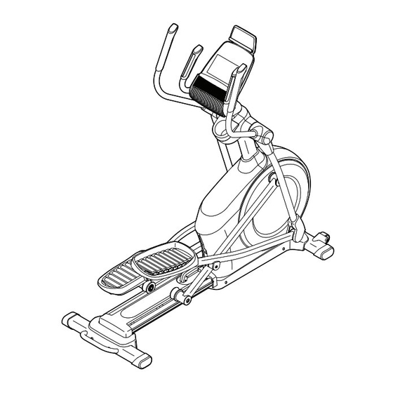
Page 7: Part Identification Chart
PART IDENTIFICATION CHART Use the drawings below to identify the small parts needed for assembly. The number in parentheses below each drawing is the key number of the part, from the PART LIST near the end of this manual. The number following the key number is the quantity needed for assembly. -
Page 8: Assembly
ASSEMBLY • To hire an authorized service technician to • To identify small parts, see page 7. assemble this product, call 1-800-445-2480. • In addition to the included tool(s), assembly • Assembly requires two persons. requires the following tools: one Phillips screwdriver •... -
Page 9: Of The Packing Materials (Not Shown) Under The
3. Press the Cover Mounts (106) on the underside of the Rear Stabilizer Cover (15) into the Rear Stabilizer (2). 4. With the help of a second person, place some of the packing materials (not shown) under the front of the Frame (1). Have the second per- son hold the Frame to prevent it from tipping while you complete this step. - Page 10 5. Orient the Upright (4) as shown. Have a second Wire person hold the Upright near the Frame (1). See the inset drawing. Locate the wire tie in the lower end of the Upright (4). Tie the wire tie to the Upper Wire (110). Then, pull the upper end of the wire tie until the Upper Wire is routed through the Upright.
- Page 11 7. Using a plastic bag to keep your fingers clean, apply some of the included grease to the Pivot Axle (35) and to two 16mm Wave Washers (54). Insert the Pivot Axle (35) through the Upright (4) and center it. Tip: It may be helpful to use a rubber mallet.
- Page 12 9. Untie and discard the wire tie on the Upper Wire (110). While a second person holds the Console (7) near the Upright (4), connect the wires on the Console to the Upper Wire (110) and to the Pulse Sensor Wires (63). Insert the excess wire into the Upright (4) or into the Console (7).
- Page 13 11. Orient the Right Pedal Arm (58) as shown. Apply grease to the axle on the Right Pedal Arm (58). Attach the Right Pedal Arm (58) to the Right Roller Arm (59) with an M8 x 14mm Shoulder Screw (120), a Small Axle Cover (55), and an M8 Washer (97).
- Page 14 13. Orient the Rear Upright Cover (81) as shown. Attach the Rear Upright Cover (81) to the Upright (4) with four M4 x 16mm Screws (101); start all the Screws, and then tighten them. Orient the Front Upright Cover (117) as shown. Attach the Front Upright Cover (117) around the Upright (4) by pressing the hooks on the Rear Upright Cover (81) onto the tabs on the Front...
- Page 15 15. Identify the Right Upper Body Leg Inner Cover (83) and orient it as shown. Attach the Right Upper Body Leg Inner Cover (83) to the Right Upper Body Leg (60) with an M4 x 16mm Screw (101) and an M5 Washer (32).
- Page 16 17. Orient the Rear Console Cover (80) as shown. Attach the Rear Console Cover (80) to the Upright (4) with two M4 x 16mm Screws (101). Orient the Front Console Cover (79) as shown. Attach the Front Console Cover (79) around the Upright (4) by pressing the hooks on the Rear Console Cover (80) onto the tabs on the Front Console Cover.
- Page 17 19. Plug the Power Adapter (119) into the receptacle on the frame of the elliptical. Note: To plug the Power Adapter (119) into an outlet, see HOW TO PLUG IN THE POWER ADAPTER on page 18. 20. Make sure that all parts are properly tightened before you use the elliptical. Note: Extra parts may be included.
-
Page 18: How To Use The Elliptical
HOW TO USE THE ELLIPTICAL HOW TO PLUG IN THE POWER ADAPTER HOW TO LEVEL THE ELLIPTICAL IMPORTANT: If the elliptical has been exposed to If the elliptical rocks cold temperatures, allow it to warm to room tem- slightly on your perature before you plug in the power adapter. - Page 19 HOW TO CHANGE THE INCLINE OF THE RAMP To vary the motion of the pedals, you can change the Upper incline of the ramp. To raise the ramp, simply pull the Body Arms ramp handle upward to the desired incline level. Handlebars Latch Button...
- Page 20 CONSOLE DIAGRAM MAKE YOUR FITNESS GOALS A REALITY WITH Upload your workout results to the iFit cloud IFIT.COM and track your accomplishments. With your new iFit-compatible fitness equipment, you can use an array of features on iFit.com to make your Set calorie, time, or distance goals for your fitness goals a reality: workouts.
- Page 21 FEATURES OF THE CONSOLE HOW TO USE THE MANUAL MODE The advanced console offers an array of features 1. Begin pedaling or press any button on the console to turn on the console. designed to make your workouts more effective and enjoyable.
- Page 22 Calories (Cals.)—This display mode will show the As you exercise, the workout intensity level bar approximate number of calories you have burned. will indicate the approximate intensity level of your exercise. Calories per Hour (Cals./Hr)—This display mode will show the approximate number of calories you are burning per hour.
- Page 23 6. When you are finished exercising, the console When your pulse is detected, a heart symbol will will turn off automatically. flash in the display each time your heart beats, one or two dashes will appear, and then your heart rate will be shown.
- Page 24 HOW TO USE AN ONBOARD WORKOUT the profile will begin to flash. If a different resis- tance level and/or target rpm is programmed for 1. Begin pedaling or press any button on the the next segment, the resistance level and/or target console to turn on the console.
- Page 25 HOW TO USE A SET-A-GOAL WORKOUT Note: The calorie goal is an estimate of the number of calories that you will burn during 1. Begin pedaling or press any button on the the workout. The actual number of calories that console to turn on the console.
- Page 26 HOW TO USE AN IFIT WORKOUT Press the Map button, the Train button, or the Lose Wt. button to download the next workout of that You must have an iFit module to use an iFit workout. type in your schedule. To purchase an iFit module at any time, go to www.iFit.com or call the telephone number on the Press the Compete button to compete in a race...
- Page 27 6. Follow your progress with the display. HOW TO USE THE SOUND SYSTEM See step 4 on page 21. To play music or audio books through the console sound system while you exercise, plug a 3.5 mm male The My Trail tab will show a map of the trail or it will to 3.5 mm male audio cable (not included) into the jack show a track and the number of laps you complete.
- Page 28 HOW TO CHANGE CONSOLE SETTINGS To view distance in miles, select ENGLISH. To view distance in kilometers, select METRIC. 1. Select the settings mode. Demo—The console features a display demo To select the settings mode, press the gear button. mode, designed to be used if the elliptical is dis- The settings information will appear in the display.
-
Page 29: Fcc Information
FCC INFORMATION This equipment has been tested and found to comply with the limits for a Class B digital device, pursuant to part 15 of the FCC Rules. These limits are designed to provide reasonable protection against harmful interference in a residential installation. This equipment generates, uses, and can radiate radio frequency energy and, if not installed and used in accordance with the instructions, may cause harmful interference to radio communications. -
Page 30: Maintenance And Troubleshooting
MAINTENANCE AND TROUBLESHOOTING MAINTENANCE Note: For clarity, the left shield is shown removed in the drawing below. Regular maintenance is important for optimal performance and to reduce wear. Inspect and prop- Next, locate the Reed Switch (38). Turn the Pulley (19) erly tighten all parts each time the elliptical is used. - Page 31 HOW TO ADJUST THE DRIVE BELT See EXPLODED DRAWING C on page 39. Remove the M4 x 19mm Screws (5) and the M4 x 48mm Screw If the pedals slip while you are pedaling, even while (107) from the Left and Right Shields (73, 74). Then, the resistance is adjusted to the highest level, the drive remove the Right Shield.
-
Page 32: Exercise Guidelines
EXERCISE GUIDELINES Burning Fat—To burn fat effectively, you must exer- WARNING: cise at a low intensity level for a sustained period of Before beginning this time. During the first few minutes of exercise, your or any exercise program, consult your physi- body uses carbohydrate calories for energy. - Page 33 SUGGESTED STRETCHES The correct form for several basic stretches is shown at the right. Move slowly as you stretch; never bounce. 1. Toe Touch Stretch Stand with your knees bent slightly and slowly bend forward from your hips. Allow your back and shoulders to relax as you reach down toward your toes as far as possible.
- Page 34 NOTES...
-
Page 35: Part List
PART LIST Model No. PFEL64915.0 R0715A Key No. Qty. Description Key No. Qty. Description Frame Roller Rear Stabilizer Pedal Arm Rear Cap Ramp Large Axle Cover Upright 16mm Wave Washer M4 x 19mm Screw Small Axle Cover Front Stabilizer Roller Arm Bushing Console Arm Bearing Left Handlebar... - Page 36 Key No. Qty. Description Key No. Qty. Description M4 x 16mm Screw M4 x 30mm Screw M8 Locknut Disc Ring M6 x 12mm Screw Front Upright Cover M10 x 122mm Screw Shield Cover Cap M10 Split Washer Power Adapter Cover Mount M8 x 14mm Shoulder Screw M4 x 48mm Screw Tablet Holder...
-
Page 37: Exploded Drawing
EXPLODED DRAWING A Model No. PFEL64915.0 R0715A... - Page 38 EXPLODED DRAWING B Model No. PFEL64915.0 R0715A...
- Page 39 EXPLODED DRAWING C Model No. PFEL64915.0 R0715A...
-
Page 40: Ordering Replacement Parts
ORDERING REPLACEMENT PARTS To order replacement parts, please see the front cover of this manual. To help us assist you, be prepared to provide the following information when contacting us: • the model number and serial number of the product (see the front cover of this manual) •...